Nikola Tesla. Tesla also designed a device for picking up energy from the air. As far as I am aware, it was never patented and I have never seen a specification of its output. Perhaps it was one of Tesla’s failures but personally, I doubt that. It might make a very interesting experiment so see what level of output can be achieved using it. The construction is shown here:
 It is essentially, a rectangular cylinder which contains two spherical electrodes like a Wimshurst machine. The cylinder is positioned vertically, so that when the electrodes are powered up with high voltage to create spark discharges, the air inside the cylinder is heated which causes it to rise up the cylinder. The heated air is ionised, so a magnetic field generated by a surrounding electromagnet, causes the charged ions to move to opposite sides of the cylinder. Electrode plates positioned inside the cylinder, provide an electrical path for the excess positive and negative charges to flow together through the load - lighting, heating or motor circuits typically. On the surface, this system would appear to be less than 100% efficient, in that the amount of power applied to the device to make it operate should be less that the amount of power drawn from it to drive useful loads. I am not sure that this is necessarily so. Firstly, the air already contains charged ions before this device starts to generate more. These naturally occurring ions gain in number when a thunderstorm is likely, even to the extent of giving many people a headache by their presence. These naturally occurring ions will be picked up by this device and without any input power needed to create them, they are capable of providing output power. Also, the whole earth is immersed in the zero-point energy field. This is seething energy at the quantum level whose effects can be seen even at ‘absolute zero’. This field is made of small random effects which makes it hard to obtain useful energy directly from it. The field needs to be structured before energy can be drawn from it. One way to do this is to align the field with an event which causes coherent waves of energy to radiate outwards as a ‘radiant energy’ wave - something like the ripples caused on the surface of a pond of still water when a large stone is dropped vertically into the water. The ripple ‘waves’ move outwards from the ‘event’ until they reach the bank of the pond. If there was a generator attached to a float in the pond, it would be possible to pick up some energy from the ripples. The same can be done with ‘radiant energy’ waves if you can create them and know how to pick up energy from them. Radiant energy waves can be formed by very short sharp uni-directional electrical pulses. Pulses less than one hundredth of a second are suitable for this. One way of creating pulses of that type is using a spark gap. In Tesla’s device shown above, sparks are generated continuously. These sparks will generate radiant energy waves radiating out at right angles to the spark. Without a doubt, the vertical cylinder will have a mass of radiant energy shooting up it when it is being operated. This is in addition to the air ions which are being picked up. The only question is whether or not the electrode plate arrangement shown is capable of picking up any of this excess energy. Considering the metallic pickup device used by Edwin Gray to capture radiant energy as described below, it seems highly likely that some of that additional energy is, in fact, picked up and used to power the loads. It should be noted that Tesla’s device shown above, will generate UV radiation in the same way as any MIG or stick welder does, so care should be exercised to avoid looking at the arc or allowing the UV to shine on your skin, even if the skin is covered by clothing. You can get serious sunburn through thin clothing if it is subjected to strong UV radiation. Also, radio interference is likely to be generated by the arc, so screening should be provided during any tests. WARNING: Tesla accidentally discovered that electric spark discharges in air, ignite and burn atmospheric oxygen and nitrogen, producing 12,000,000 volt waves. The oxygen and nitrogen, both below atomic number 19 are thereby transmuted into alpha and beta charges (stripped helium nuclei with +2 charge each, and electrons with -1 charges each) by the powerful radiation produced, having a voltage potential of 12 Mev. This is almost three times the Mev level of gamma radiation emitted by radium, it may well be the reason why Tesla did not publicise the device shown above, and should you decide to experiment with it, please be aware of the potential hazard of this radiation. A variation on the above device of Tesla’s is given in the book “Physical Chemistry” by E. A. Moelwyn-Hughes, Pergamon Press, Oxford 1965, page 224. Rutherford and Geiger determined the fact that radium puts out alpha particles at the rate of 34,000,000,000 per second, each having two units of positive charge at 4.5 million electron-volts. This is a staggering amount of energy which ionises the air inside the housing and produces enough power to be capable of replacing the entire Four Corners power complex indefinitely.  The variation of Tesla’s device shown above, supports the lead container with its gram of radium on a strap across the bottom of the housing. The radiation ionises the air and the magnetic field separates the charges and directs them to opposite sides of the housing, to be collected and used via the electrode plates. There does not appear to be any reason why strong permanent magnets should not be used instead of the DC electromagnet shown. Paulo & Alexandra Correa have discovered a way of converting Tesla’s longitudinal waves into ordinary electrical power. They have made US Patent Application 2006/0,082,334 entitled “Energy Conversion Systems” in which they show various ways of achieving this energy-type conversion. Their techniques range from applying the longitudinal wave energy coming from a Tesla Coil directly to two capacitors via diode rectification and the voltages generated are related directly to actual ground earth potential:  The patent application is in the Appendix so the full details can be examined. A theory of operation is presented based on their many experiments and observations, and the practical form of one of their conversion devices is:  Where the active pick-up plates R and T are encased in a cylinder and are provided with a cone shape to assist the procedure. The patent application contains a good deal of information and is worth reading. Professor Konstantin Meyl. Another key person in the advancement of current theory and analysis is Professor Konstantin Meyl who has described how field vortices form scalar waves. He has described how electromagnetic waves (transverse waves) and scalar waves (longitudinal waves) both should be represented in wave equations. For comparison, transverse EM waves are best used for broadcast transmissions like television, while longitudinal scalar waves are better for one-to-one communication systems like cell phones.  He also presented the theory that neutrinos are scalar waves moving faster than the speed of light. When moving at the speed of light, they are photons. When a neutrino is slowed to below the speed of light, it becomes an electron. Neutrinos can oscillate between e- and e+. Fusion involves e-, and a lightning flash involves e+. Energy in a vortex acts as a frequency converter. The measurable mixture of frequencies is called noise. Dr. Meyl has pointed out that Tesla measured the resonance of the Earth at 12 Hz. The Schumann resonance of the Earth is 7.8 Hz. Meyl shows how one can calculate the scalar wave of the Earth to be 1.54 times the speed of light. He has developed a model which ties the expansion of the earth to be the result of the earth’s absorption of neutrino energy. The ramifications of this model are that neutrino energy can be tapped. He took this to the next step and postulated that Zero Point Energy is neutrino power – energy from the field; available at anytime, and everywhere present. To show the place of neutrinos in conventional science, Meyl noted that the 2002 Nobel Physics prize was in regards to work on neutrinos. Dr. Meyl’s web site is here and if you access it via Google, a rough translation into English is available. Nikola Tesla. Tesla performed an experiment in which he applied high-voltage high-frequency alternating current to a pair of parallel metal plates. He found that the ‘space’ between the plates became what he described as “solid-state” exhibiting the attributes of mass, inertia and momentum. That is, the area transformed into a state against which a mechanical push could be exerted. This implied that, using this technique, it should be possible to produce a spaceship drive anywhere in space, if the mechanism for thrusting against the ‘solid-state’ space could be determined. Further experiments convinced Tesla that powerful electromagnetic waves could be used to push against (and pull against) what appears to be ‘empty space’. The drive principle is based on the Hall-effect used in semiconductor magnetic sensors, and is called the magnetohydrodynamic (“MHD”) effect. This might be illustrated like this:  Here, a box is constructed with two metal plates forming opposite sides and two insulating plates holding them in position and surrounding an area of ‘space’. High-frequency, high-voltage alternating current is applied to the metal plates and this creates an electric field “E” acting between the plates as shown in black. A magnetic field “B” is generated by the electrical field. The magnetic field acts at right-angles to the electric field, as shown in blue. These two fields produce a propulsion thrust “F” shown in red in the diagram. This propulsion force is not produced by ejecting any matter out of the box, instead, it is produced by a reaction against the ‘solid-state’ condition of space-time caused by the high-frequency electromagnetic pulsing of that area of space. This is enormously more effective than a jet engine. The thrust increases with the fourth power of the frequency, so if you double the frequency, the effect is sixteen times greater. To put this into perspective, consider the force being applied against gravity to lift an object into the air. The force pulling the object downwards is gravity and its strength is given by: Gravitational force: F = g x M x m / r2 where g is the gravitational constant (6.672 x 10⁻⁸ cm3 g-1 s-2) M is the mass of the first body m is the mass of the second body and r is distance between the two centres of mass The lifting force is given by: Lorentz Force: Force on an object = Electric force + Magnetic force F = q x E + q x v x B where q is the charge on the object, B is the magnetic field, v is the velocity of the object and E is the electric field How do these forces compare? Well, the electromagnetic force is stronger than the gravitational force by a factor of about 2,200,000,000,000,000,000,000,000,000,000,000,000,000 times. That number (2.2 x 1039) is too big for anybody to really visualise, so let me put it another way. If the amount of energy used to mechanically lift an object a distance of one hundredth of an inch (one quarter of a millimetre) off the ground, were used as an electromagnetic lifting force, then that amount of energy would lift the object more than 3,472,222,000,000,000,000,000,000 miles off the ground, or in metric units, more than 5,588,001,700,000,000,000,000,000 kilometres off the ground. This kind of drive is an entirely different kind of animal. This Hall-effect type of drive if used in a spaceship would require only a very small amount of input power to drive the ship at great speeds and over great distances. As the device shown above operates directly on the space-time field which penetrates all matter, there would appear to be no reason why it should not be used to drive a conventional vehicle by positioning it in a horizontal position rather than the vertical position shown in the diagram. Throttle operation could be by very slight adjustment to the frequency of the AC pulses applied to the metal plates. However, Bill Lyne indicates that horizontal movement is better achieved by producing Tesla’s very short, high-voltage high-frequency DC pulses at the front of the vehicle while at the same time generating very high-voltage high-frequency AC waves at the back of the vehicle. This style of drive is said to pull the vehicle along rather than push it along. The Unified Field Theory is being searched for by scientists who want to come up with a theory which encompasses the force of gravity with the electromagnetic force. In my opinion, they would have more chance of success in trying to find a needle in a haystack which does not contain a needle since when the entire haystack has been disassembled, it becomes clear that there never was a needle in it. In my opinion, there is no such thing as a “force of gravity”, in fact, there is no such thing as gravity. Find that hard to believe? Well, let me explain. If when standing, you hold an object a waist level and let it go, it “falls” and lands near your feet. Yes agreed, and yet I suggest that there is no such thing as gravity. If you suspend a pendulum close to a mountain, the pendulum does not hang down vertically but moves slightly towards the mountain. This is said to be because the mountain attracts the pendulum. Sorry Chief, but that just ain’t true - the mountain does not attract the pendulum. The reason why “the force of gravity” is so tiny compared to electromagnetism is because there is no such force at all. Yes, indeed, all of the observed phenomena which are supposed to be gravitational, do exist exactly as seen, but I suggest that there is no such thing as “the force of gravity” and the Unified Field Theory is not needed. Let me explain: The Zero-Point Energy field exists everywhere in the universe and it flows in every direction equally. It acts like a flow of particles thousands of times more tiny than electrons, and so, it flows through matter. No matter can shield completely from the flow of this energy field. But, a tiny percentage of the flow does happen to collide with the electrons, atoms and molecules of matter as the energy flow moves through matter. The bigger the chunk of matter, the more of the energy flow collides with it. The collisions convert the energy into additional mass, which is why our Sun is not losing mass as rapidly as theory would predict. The situation is like this:  The force of the Zero-Point Energy field is slightly reduced having passed through (and interacted with) the large mass of the Earth. This reduced strength in indicated in the diagram by the light-blue arrows. The incoming Zero-Point Energy field is not reduced in strength in any significant way as the molecules in the atmosphere are not nearly as tightly packed as those in the matter which makes up the Earth itself. The imbalance of these two thrusts causes a net push towards the surface of the Earth. For clarity, the diagram only shows the field acting in one direction, while in reality, the same situation applies in every possible direction around the planet. When you let an object go and it moves towards the surface of the planet, it is not being pulled down by “the force of gravity”, but instead, the downward push of the Zero-Point Energy field is greater than the upward push of the Zero-Point Energy field which has just passed through the planet. The object moves “downwards” because the push from above is greater than the push from below. Exactly the same thing applies to cause the effect that a mountain appears to have on a pendulum. In reality, the mountain has no effect on the pendulum, apart perhaps from a minor electrostatic influence. The main effect is caused by the flow of the Zero-Point Energy field:  Here, the (very roughly drawn) mountain, reduces the push of the Zero-Point Energy field which passes through it, due to its interaction with the matter with which it collides on its trip through the mountain. The push of the Zero-Point Energy field on the side of the pendulum is not diminished, so there is a net push towards the mountain and that makes the pendulum move in the direction of the mountain. The effect is not very large, so the pendulum does not move much out of the vertical as the downward push towards the surface of the planet is quite marked, so the pendulum needs to be very near the mountain for this effect to be observed. This can also be seen in the Casimir Effect where two non-magnetic metal plates, which are not carrying an electrostatic charge, are suspended very close to each other. The plates do not hang straight down but move towards each other. This is the same effect as is caused by a mountain near a stationary pendulum, or plumb-line. Each plate screens out a little of the Zero-Point Energy field which passes directly through both plates, so the second plate gets slightly less of a push:  The result is that between the plates, the horizontal force pushing them is unbalanced. Hang just one plate up and the horizontal Zero-Point Energy (“ZPE”) forces coming from the right exactly balance the ZPE forces coming from the left, and the plate hangs vertically below its point of suspension with the supporting cord (shown in red in the diagram above) hangs vertically. But with two plates as shown, the push from the left is reduced very slightly as it passes through the left hand metal plate. This means that there is a lesser push from left to right on the right hand plate. This causes the plate to move very slightly to the left, until the horizontal pull caused by the red cord not being vertical, just balances the difference in the ZPE thrusts on that plate. So, the right hand plate moves slightly to the left. The same thing happens with the left hand plate. The ZPE thrust coming from the right is slightly reduced as it passes through the right hand plate, and the left hand plate moves slightly to the right until the angled pull of its supporting cord balances the net thrust on that plate. The overall effect is that the gap at point “A” in the diagram is very slightly larger than the gap at point “B”, though the amount is not nearly as great as suggested by the diagram, which has been deliberately exaggerated to show the effect clearly. There is nothing complicated about this, it is just simple common sense. Remember that the pull of the supporting cord “C” is the exact equivalent of a vertical force “D” along with a horizontal force “E”. Here, the vertical force D exactly matches the weight of the plate, and the horizontal force E exactly matches the unbalanced ZPE force (if they did not match exactly, then the plate would move until they did). The further away from the vertical that the plate moves, the greater the resulting horizontal force caused by the pull of the supporting cord. Tesla expressed this in a very slightly different way in his Dynamic Theory of Gravity (1897) which states that all bodies emit microwaves whose voltage and frequency are determined by their electrical contents and relative motion. He measured the microwave radiation of the earth as being only a few centimetres in wavelength. He said that the frequency and voltage were influenced by the velocity and mass of the earth, and that its “gravitational” interaction with other bodies, such as the sun, was determined by the interaction of the microwaves between the two bodies. If you find the concept of producing a driving force through pushing against the space-time continuum to be difficult to accept, then perhaps you should consider the US Patent granted to Boris Volfson on 1st November 2005. The important thing about this patent (which is crammed full of long words) is not whether or not it presents a realistic mechanism for a practical space drive, but the fact that the US Patent Office in the year 2005, granted the patent after what presumably was careful consideration. With that in view, it is hardly possible to consider Tesla to have been totally confused when he designed (and built) his “electric flying machine” which operated by pulling on the space-time field. Tesla used high voltage at gigahertz frequencies for his electropulsion system. The propulsion of a vehicle powered by a Tesla drive is by the use of an additional AC generator at the back (which stiffens the space-time continuum behind the vehicle) and a DC ‘brush’ generator at the front (which weakens the space-time continuum in front, causing the vehicle to be pulled forwards). Tesla was very astute. He deduced that ‘empty space’ actually contained:
When we grasp the actual nature of the universe, it becomes clear that we have a much larger range of opportunities for producing usable energy in large quantities and at minimal cost. Additional information can be found in Boris Volfson’s US Patent 6,960,975 of November 2005 “Space Vehicle Propelled by the Pressure of Inflationary Vacuum State” which is reproduced in the Appendix. If you find the thought of generating a gravitational field, difficult to come to terms with, then consider the work of Henry Wallace who was an engineer at General Electric about 25 years ago, and who developed some incredible inventions relating to the underlying physics of the gravitational field. Few people have heard of him or his work. Wallace discovered that a force field, similar or related to the gravitational field, results from the interaction of relatively moving masses. He built machines which demonstrated that this field could be generated by spinning masses of elemental material having an odd number of nucleons -- i.e. a nucleus having a multiple half-integral value of h-bar, the quantum of angular momentum. Wallace used bismuth or copper material for his rotating bodies and "kinnemassic" field concentrators. Aside from the immense benefits to humanity which could result from a better understanding of the physical nature of gravity, and other fundamental forces, Wallace's inventions could have enormous practical value in countering gravity or converting gravitational force fields into energy for doing useful work. So, why has no one heard of him? One might think that the discoverer of important knowledge such as this would be heralded as a great scientist and nominated for dynamite prizes. Could it be that his invention does not work? Anyone can get the patents. Study them -- Wallace -- General Electric -- detailed descriptions of operations -- measurements of effects -- drawings and models -- it is authentic. If you are handy with tools, then you can even build it yourself. It does work. Henry was granted two patents in this field: US Patent 3,626,605 -- "Method and Apparatus for Generating a Secondary Gravitational Force Field", Dec 14, 1971 and US Patent 3,626,606 -- "Method and Apparatus for Generating a Dynamic Force Field", Dec 14, 1971. He was also granted US Patent 3,823,570 -- "Heat Pump" (based on technology similar to the above two inventions), July 16, 1973. Dr Peter Lindemann gave a lecture at the TeslaTech conference which is very informative and which I would highly recommend. It is available on DVD from here under the title of "Tesla's Radiant Energy". He makes a number of important points, some of which are repeated here. We tend to think of the battle for industrial electricity to have been between Thomas Edison's DC system and Tesla's AC system, with Tesla winning. Unfortunately, while true, that is not the full story as Tesla moved on from AC to more powerful systems, and Tesla lost out on those systems, leaving us today, with a workable, but much inferior system. We need to see the overall picture clearly. James Clerk Maxwell produced his famous equations, relating electricity and magnetism (which are actually two faces of a single entity called "electromagnetism"). Subsequently, H.A. Lorentz damaged those equations, throwing away the parts which showed that free-energy was available for use if we knew how to access it. Out present day position has grown up where, while we realise that "gravity" is 1039 times less powerful than electromagnetism, we see "static electricity" as a weak and useless thing which needs to be avoided. The reality is quite different as Tesla points out and demonstrates. Tesla describes "static" and "radiant" energy as being a force which appears to have no ultimate limits at all. That is, it is capable of providing unlimited power. Our knowledge of this power is so inadequate that we believe that power can only flow in a circuit which is a closed-loop and the power flow has to be a stream of electrons. This is most definitely not the case. The more powerful radiant energy flows like an electrically charged sound wave passing through incompressible air and which can be fed down a single wire without the slightest difficulty. In fact, you can even skip that one wire and use the earth instead, transmitting power with what appears to be no wires at all. The actual, final and most important contest was between closed-loop electricity and single-wire power transmission, and that contest was one which Tesla lost. The nature of this radiant energy is so different to what we think of as conventional electricity that it is perfectly possible to light a filament light bulb held in one hand, while grasping a single wire in the other hand. When doing this, there is no sensation whatsoever and nothing at all is felt. Videos on this suibject are here and here at this time. An excellent set of teaching videos are at Borderland Sciences. In his lecture, Dr Lindemann remarks that his understanding of the subject has been helped considerably by the book "The Inventions, Researches and Writings of Nikola Tesla" and the book "The Secrets of Cold War Technology - HAARP and Beyond" which describes some of the early work done by Tesla. He also praises the book "Tesla's Vocabulary for Dummies" which is unobtainable, though he does show some quotations from it in his DVD lecture. One feature of radiant energy which becomes clear from Tesla's description of it, is that the most useful effects which can be gained from it, start at a DC pulse frequency of 1 MHz which is far higher than experimenters use today. He stresses that we do not actually know the exact nature of electricity and that all of our present day measuring instruments are based on electron theory and so just do not measure radiant energy. In a way, it is a bit like the difference between AM radio and FM radio. Both are perfectly valid and work well, but an AM radio will not receive an FM radio signal and an FM radio will not receive an AM radio signal. Unfortunately, radiant energy is much more powerful than conventional electricity and it is not dangerous like electricity is. It should be noted that Hermann Plauston's very detailed patent US 1,540,988 is on methods of capturing and using this radiant energy, and he describes a systems which produces a net output of 100 kilowatts as being a "small" system. I don't know about you, but I would settle for a system which produced less than 10% of that fuel-less output. The best information on radiant energy comes from the writing of Tesla and Dr Lindemann draws attention to one of Tesla's patents US 685,957 which explains how this radiant energy can be captured and used. Tesla also used a motor design which is effective with this type of energy. The motor has two windings, the first being fed directly and the second one receiving a 90 degree delayed pulse through a capacitor. One thing that Tesla points out is that there is an incompressible gaseous medium filling the universe and which is composed of particles which are much smaller than hydrogen atoms. Mendeleev who constructed the table of elements indicates quite clearly that there should be two gaseous elements which are lighter than hydrogen, but he did not put them in his table because he did not know what they are. The Permanent Magnet Drive / Generator. John R.R. Searle of Britain is stated to be a con artist by his co-workers. "His" electrical generation system based on two rings of magnets being spun relative to one another. The magnet orientations oppose each other to produce a magnetic splatter field.  Dr. Terry Moore has recently built a replication model of this Searle technology and his model video is available on YouTube. The Searle device also demonstrates a gravitic effect and John has built what would loosely be described as a “flying disc” using this technology. If high voltage is applied to the device when it is rotating, then a surrounding corona develops and strong upward electrogravitic forces are generated. The Gravity Wave Detector. It has been reported that Nikola Tesla made a device which allowed him to hear sounds at great distances. I have never seen any details of the circuitry used by Tesla. However, Dave Lawton has produced such a device, and he reports that he could hear conversations taking place four and a half miles away from him. Interestingly, the sounds from that distance were also travelling through a solid stone wall some three feet thick. The circuit for this device is described in this document. In my opinion, the device is not picking up audio signals in the manner of a conventional microphone where air pressure waves vibrate a transducer, creating an electrical signal which is then amplified. The interesting thing is that it is distinctly possible that some other mechanism is coming into play here. This opinion is supported by the fact that Dave’s circuit is an upgraded version of a monopole gravity-wave detector. Dave used this device to record the “sound” of the Shumaker-Levy comet colliding with Jupiter. The circuit shown here is quite conventional electronically speaking, comprising of two 741 operational amplifiers connected as a two-stage amplifier. The unusual feature is where a small amount of white noise is being fed into the microphone input:  The white noise is generated by the 5-volt zener diode. The level of this white noise component is controlled by the 1.5 megohm variable resistor plus the 10K fixed limiting resistor. While the range of these two components is 10K to 1.501 Meg. the working setting is normally very high and so only a very small amount of white noise is fed into the input of the first 741 op. amp. to modify the microphone input. The adjustment of this injection of white noise is the main control of this most unusual circuit, and it has been found that when the setting is just right, the circuit has the feel of a public address system just about to go unstable from positive feedback. The unit build looks like this:  The theory of operation was put forward by Gregory Hodowanec in the April 1986 issue of the Radio-Electronics Magazine, where he puts forward the theory that the source of noise in electronic devices is caused by gravitational waves and he suggests that there are monopole gravity waves. This does not oppose the gravity waves predicted by Einstein. Gregory views these monopole gravity waves as being much stronger than those suggested by Einstein, and consequently, much easier to detect. He also suggests that monopole gravity waves have been seen for many years and have been described as “low frequency noise” signals or “flicker noise”. These signals have also been called Microwave Background Radiation, supposedly caused by the “Big-Bang” though this cause is disputed by some. Gregory views our universe as a finite, spherical, closed system, i.e. a black body. Monopole gravity waves propagate in Planck time so their effects appear everywhere almost simultaneously. Gravity wave energy can be imparted to ordinary objects. So it is suggested that the fact that a fully discharged electrolytic capacitor can develop a charge when disconnected from all circuitry, is down to the interaction of the capacitor with monopole gravity waves. Gregory suggests the following circuit for examining monopole gravity waves:  Details of this and the theory can be found here. Dave has taken that circuit and extended it substantially to give added gain plus a controlled feed of white noise, without relying on the characteristics of a capacitor, capacitors being notoriously variable in precise characteristics. The unit is operated by turning the gain up until the circuit just reaches self-oscillation, and then backing the gain off very slightly. The white noise source is then adjusted until the unit is producing a somewhat echoing quality to the sound. The result is a device which has unusual characteristics. The circuitry is so simple and cheap, that you can easily try it out for yourself. The Butch Lafonte Motor / Generator. Butch has designed an intriguing Motor / Generator system based on the balancing of magnetic and electrical forces. This clever design operates according to the following statements made by Butch: 1. If a magnet is moved away from an iron-cored coil, it generates a voltage:  The voltage generated for any given magnet and speed of movement, is directly proportional to the number of turns of wire which make up the coil. 2. If a magnet is moved away from an air-cored coil, it also generates a voltage. However, the big difference is that the voltage is of the opposite polarity. In other words, the plus and minus connections are swapped over:  Again, the voltage generated for any given magnet and speed of movement, is directly proportional to the number of turns of wire which make up the coil. So, if these two arrangements are joined together, they produce a system where the voltages cancel each other exactly, provided that the number of turns in each coil are adjusted to produce exactly the same voltages. The mechanical attraction and repulsion forces also balance, so the circuit can be arranged to have no net effect when the rotor is rotated:  It follows then, that this motor arrangement could be introduced into an existing circuit without affecting the operation of that circuit. The arrangement would look like this:  Here, there is no net electrical or magnetic drag on the rotor as the magnets move away from the coils. The battery supplies current to the load in the normal way and rotor arrangement has no effect on the operation of the circuit. However, when the rotor reaches 100o or so, past the coils, the On/Off switch can be opened. This leaves the rotor in an unbalanced condition, with there being an attraction between one magnet and the iron core of one coil. There is no matching repulsion between the other magnet and the air core of the other coil. This produces a rotational force on the rotor shaft, keeping it spinning and providing useful mechanical power which can be used to generate additional power. This extra mechanical power is effectively free, as the original circuit is not affected by the inclusion of the rotor system. From a practical point of view, to give high rotational speed and long reliable life, the On/Off switch would need to be an FET transistor with electronic timing related to the rotor position. There is no need for the rotor to have only two magnets. It would be more efficient if it had four:  Or better still, eight:  And if you are going to have eight, there is no need to have the V-shaped cut-outs which just create turbulence when spinning, so make the rotor circular:  And the stator supporting the coils matches the rotor:  Ferrite is a better material for the cores of the coils. The stators go each side of the rotors and the hole in the middle of the stators is to give clearance for the shaft on which the rotors are mounted:  A system of this type needs accurate timing which is solely related to the rate of rotation. This is best arranged by the use of a bistable multivibrator as described in the Electronics Tutorial of Chapter 12. You will notice the two Timing Coils shown at the right hand side of the diagram above. These are used to toggle the bistable On and Off and they are adjustable in position so that both the On and the Off can be set very precisely. The output of the bistable is set to switch an FET transistor On and Off to give circuit switching which is not affected by either the switching rate or the number of times the switch is operated. The Rotor / Stator combination can be wired to act as either a driving Motor or an electrical Generator. The difference is the addition of one diode:  With this arrangement, for each rotor, all four pairs of Cored coils are wired in parallel across each other, and all four Air-cored coils are wired in parallel across each other. To improve the clarity, the above diagram shows only one of the four pairs, but in reality, there will be four wires coming into the left hand side of each of the screw terminals.  Further details of this Motor / Generator can be seen here. The Joseph Newman Motor. Joseph Newman is a man who impresses me. He performs experiments, reports the results and then bases theoretical conclusions on the results of his own experiments. This is the true scientific method.  Joseph has been granted a patent and he has written a book. I would recommend that you buy a copy of his book and help support his work by doing that, but unfortunately, as I understand it, the printing plates for the book were destroyed in a fire and printed copies of his book are effectively unobtainable. You can download a .pdf version from the www.free-energy-info.tuks.nl web site but please be aware that the overall file size is 100 Mb and so the download will take quite some time. A background download can be had from here or alternatively here while the link to Joseph’s own web site is here. In very brief outline, Joseph has built a motor which can access free energy. He has a theory about where the excess energy is coming from and how it is acquired by his designs. He has also built a large stationary motor to demonstrate his theory and he has built a motor into a car. The car engine runs on very minor battery power and can be seen here. Joseph’s patent is included in the Appendix of the eBook. With the kind permission of the Joseph Newman organisation, I am going to attempt to introduce you to the important scientific conclusions reached by Joseph and the Energy Machine which he designed and which is based on those conclusions. Joseph has a keen enquiring mind and thinks things through for himself rather than blindly accepting everything he is told. This description contains illustrations and wording taken from parts of Joseph’s book published in 1984, and I should like to express my thanks for being given permission to use this material. Joseph Newman’s motors all consist of a very powerful permanent magnet which rotates or oscillates in or near a coil with a very large number of turns of copper wire. The coil is energised by a battery pack, and the magnetic field produced by the coil provides the force needed to move the permanent magnet. A mechanical switching device or “commutator” reverses the direction of current flow through the coil every half cycle, and in some models, it also cuts off the current input between the current reversals. The main difference between Joseph’s designs and previous motors is one of scale as Joseph uses very large coils and very large ceramic magnets weighing up to 700 pounds. His smaller motors use powerful rare earth magnets and the coils are wound with 100,000 turns of copper wire. This creates a very high coil resistance and the battery pack voltages are correspondingly high, being in the hundreds to thousands of volts range. The torque or turning power applied to the magnet in these motors is proportional to the magnet strength, the number of turns in the coil and the current flowing in the coil. In Joseph’s motors, very large torques can be developed by very small currents. In one demonstration, a motor running on 3,000 volts at 0.8 milliamps has such power that it is not possible to stop the motor by holding its two-inch (50 mm) diameter shaft, though the current can be raised by trying to stop it, to 3 milliamps, or nine watts of power. Joseph’s motors are different in other ways. If fluorescent tubes are connected across the motor coil, they light up due to the coil’s collapsing magnetic field each time the current direction is switched. These fluorescent tubes are used to protect the mechanical switch from arcing damage. The additional power produced in these tubes is at a very high frequency of 10 to 20 MHz. This radio-frequency current has been accurately measured and it exceeds the battery input current by a factor of five to ten times in the different motors. The measured current and voltage were in phase, indicating a real power output. To understand the thinking behind these motors, we need to follow Joseph’s experiments and the deductions which he made from those experimental results. Joseph considered, and thought carefully about statements made by the two scientific giants James Clerk Maxwell and Michael Faraday, and this led him to valuable insights: It appears that Maxwell and Faraday were the only people who considered that “lines” of magnetic force are actual physical entities and not just a method of representing notional forces and those “lines of force” are actually streams of matter in motion. Maxwell says: “In speaking of the Energy of the field, however, I wish to be understood literally. All energy is the same as mechanical energy, whether it exists in the form of motion or in that of elasticity, or in any other form. The energy in electromagnetic phenomena is mechanical energy”. Joseph then considered Michael Faraday’s Electrical Generator and the implications of the way in which it operated:  Here, a loop of wire is moved downwards from level “A” to level “B”. This movement causes an electrical current to flow leftwards along the wire as shown by the red arrows. Joseph’s question was “why does it go in that direction every time the wire is moved in that way?”  If the wire is moved upwards through the same magnetic field, then the current flowing in the wire moves in the opposite direction. Why? How does the current “know” which way to go?  If you turn the magnetic field round by reversing the position of the magnetic fields and then move the wire loop in the same way as before, the current flows in the opposite direction. How does the current “know” which way to flow, or which way round the magnets are turned as it does not touch them?  The next interesting point is that if the wire loop is moved up and down between the magnets, but turned to be parallel to the flux flowing between the poles, then no current flows in the wire, no matter how quickly the wire is moved up and down.  Another point is that if the wire loop is moved slowly up through the magnetic flux, the electric current which flows as a result of that slow movement, moves at the speed of light, flowing from “A” towards “B”.  Now, if the wire loop is disconnected and turned over, the part which was at “A” now moved to “B”, and the same movement of the wire carried out - the current flow is in exactly the same direction although its path along the wire is reversed (because the wire has been reversed). This shows that the direction of current flow is not affected by the wire itself. According to conventional teachings, this electric current flow was not a result of the magnetic field as the magnetic lines of force were supposed to be imaginary, consisting of Potential Energy and no Kinetic Energy. It became clear to Joseph that this conventional teaching was wrong. Instead, it seemed clear that the magnetic field consists of particles which have mechanical characteristics, and those particles must be moving at the speed of light within the magnetic field. A key question seemed to be: “how does the current ‘know’ which direction to flow?” as the direction was always consistent. After careful consideration, it occurred to Joseph that the answer was provided by the actions of a gyroscope:  Here, if the axle of the spinning flywheel, or gyroscope, is pressed downwards it moves off in the direction shown by the red arrows. However, if the axle is pressed upwards:  then the axle moves in the opposite direction as shown by the red arrows. This effect is, of course, reversed if the direction of rotation of the gyroscope is reversed (as it will be if viewed from the other side, in the same way as the current flow direction in the wire is reversed if the magnetic poles are swapped over). Now, if the gyroscope axle is moved up and down equally on both sides, there is no resulting sideways force:  The action of the gyroscope axle matched the current flow in the wire in every respect, so it became clear to Joseph that the particles flowing between the poles of the magnet were spinning as well as moving at the speed of light. This gyroscopic mechanical motion of the particles accounts for all of the characteristics of the current flow in a wire which is being moved through a magnetic field. This is a major insight on the part of Joseph. May I remark that these particles are not coming from the magnet itself, but are flowing in from the zero-point energy field, that flow being caused by the broken symmetry of the zero-point energy field generated by the dipole effect of the poles of the magnet. That is why energy can (appear to) be drawn from magnets for years on end. Joseph then went on to consider the physical aspects of permanent magnets. There were two very significant facts which had to be considered. The first of these is that different materials have markedly different magnetic characteristics:  A bar of soft iron does become a permanent magnet when pulsed briefly with a strong magnetic field, but if exactly the same level of magnetic pulsing is applied to a similar bar of an alloy of iron, nickel and cobalt, a permanent magnet is also produced, but the magnetic field of the alloy is very much stronger than that of the soft iron bar. This shows that the molecular structure of the bar has a major effect on the resulting magnet. In passing, please be aware that the more powerful magnets available nowadays are so strong that they can easily injure you. If you pick up a magnet and inadvertently get close to a second one, the loose magnet will jump some inches and try to connect to the one in your hand, crushing your fingers in the process and proving very hard indeed to shift in order to deal with the injury. I have also seen it alleged that US ‘AlNiCo’ (Aluminium / Nickel / Cobalt alloy) magnets are deliberately doped with K40 isotope which renders them useless fairly quickly. The source of this information is highly dubious, but the extra sales advantages to the magnet manufacturers would be significant. Also, the advantages for the people wanting to suppress the creation of free-energy magnet motors would be major as many talented US inventors are likely to think that their successful magnet motors were failures because the magnets appeared to be “drained of power” by being used in their design, when in fact, the design is perfectly good. So I will leave you to make up your own mind about the matter and remark that Bill Muller found that his powerful Chinese-manufactured magnets were in perfect condition after eleven years of use. Another point which Joseph considered was the fact that when successive magnetic pulses are applied to a ferromagnetic metal bar, the resulting magnetic field strength reaches a definite maximum value, and further pulsing has no further beneficial effect:  This is considered to be the magnetic pulse aligning atoms in the metal. Eventually, all of the atoms are aligned and so not further effect can be produced by further pulsing. This alignment can be destroyed if the metal bar is heated to a sufficiently high temperature, forcing the atoms into such an energetic state that the alignment is lost. It should perhaps, be stressed here, that the magnet itself does not have any power, in spite of seeming to have. Tom Bearden explains this clearly by pointing out that what happens is that the opposite poles of the magnet created a “dipole” which unbalances the random ‘quantum foam’ nature of the local environment (the zero-point energy field) and that causes continuous energy flows from the environment. The “magnet” power is coming from the environment and not from the magnet itself. If you find this hard to believe and think that you are just getting back the electromagnetic energy which you pumped into the metal when creating the magnet in the first place, then apply simple arithmetic. Assume that you get back exactly 100% of the original power and calculate how long that amount of power would allow the magnet support its own weight against gravity, when attached to a vertical metal surface. Then ask yourself how come the magnet can do it for years and years on end. Point proved conclusively? Joseph concluded that the attraction of “unlike” magnetic poles and the repulsion of “like” poles is caused by the gyroscopic spin direction of the actual physical streams of the “lines of force”, which he has shown that both of the scientific giants, Maxwell and Faraday were convinced were actual physical entities. The intuitive genius Nikola Tesla described the zero-point energy field as having the physical characteristics of a gas, capable of having motion, exerting pressure, and yet having particle size so small that it can flow through any physical material. Joseph has concluded that this field flow has a specific spin direction as it flows, certainly for flows caused by the magnetic dipole of a magnet. It should be remembered that the scientific teaching of present day educational institutions is at least fifty years out of date. We have the most unusual situation where the scientific literature of a hundred years ago is actually of better quality than that of today which does not describe the actual world at all well. Currently, misconception is alive and very well. For example, Maxwell produced equations describing how the world works. Admittedly, these equations are very difficult for people to understand. H. A. Lorentz simplified these equations and his results are mistakenly described as Maxwell’s which they most certainly are not. Tom Beardon illustrates it this way; consider a sailing boat being driven along by the force of the wind against the sails:  Maxwell says that there is a vast swathe of wind blowing across the ocean, capable of powering a long row of a thousand sailing boats side by side. This is the actual physical case. Lorentz has ‘simplified’ things by saying “we will consider one boat and only one boat. As the rest of the wind does not touch any part of the boat we can ignore it”. While that is true for that one boat, what science teaching now says is that the wind can only power a single boat. This is not the actual case, as the environmental wind is not limited to powering just one boat (sailing regattas would not be much fun if that were the case!). This, of course, is just an illustration. Maxwell’s equations cover energy and power for the whole universe, and deal with all cases. Lorentz has taken a sub-set of the conditions described by Maxwell’s equations, just the group which apply to “closed systems” – just one boat on the ocean. Science has latched on to this and now confidently states that everything is a “closed” system, when in fact, as the zero-point energy field flows through everything, everywhere at all times, and is capable of supplying unlimited additional energy anywhere at any time, there is probably not a single instance of a “closed” system anywhere in the universe. Joseph Newman, and all other serious inventors, have to fight against this “conventional” science teaching, which is now so entrenched that it has become the equivalent of religious dogma, and ‘scientists’ are unwilling to consider valid observations which do not fit in with the very limited Lorentz concept of the environment. They say “perpetual motion is impossible” which means that Newton was wrong when he said that a moving body will keep on moving indefinitely unless some force acts on it to stop it. You can see then, that when Joseph performs tests and then bases his conclusions on the results of those tests, that he is applying the true scientific method, and people who say that his verified results are impossible because Lorentz says so, are not being scientifically honest. No honest person can ignore genuine scientific observations. Joseph’s deduction that magnetic lines of force are formed of actual physical particles spinning in gyroscopic motion as they move along their magnetic path at the speed of light, was not something which was obvious to scientists, in spite of the fact that both Maxwell and Faraday had both explicitly described these lines of force as being ‘kinetic magnetic energy’:  As a wire passes in front of and across the end of a bar magnet, the current flows in one direction, pauses, and then flows in the opposite direction. This occurs due to the gyroscopic flow direction of the particles. For instance, on one side of the South end of the magnet, the lines of force spin “up” while on the other side of that same South end, they spin “down”. A spinning gyroscope will move at right angles to the force acting on it, so as the gyroscopically spinning particles encounter the particles of the wire, they move “up” or “down” the wire at right angles to the direction in which they first encounter the wire. Please note that it is the gyroscopic spin direction of the particles which determines magnetic ‘attraction’ or ‘repulsion’ and not the direction of flow of those particles along their line of force:  It should also be realised that although we draw ‘lines’ of force around a magnetic device, the reality is that these are really shells of force and the magnetic flow is really like water flowing in a river. While we may draw arrows to indicate direction and strength of currents in a diagram of the river, the reality is, of course, that there is water flowing at all points in the river and not just along the lines which we decide to draw. The same applies to the magnetic flow around a magnet, it exists like a solid mass flowing through and around the magnet. You don’t see it or feel it because the particles are so small. Now to the details of how to construct a device to take advantage of this magnetic movement and output more power than is required to make it operate. Let me remind you again that we are talking here of a Coefficient of Performance (COP) which is greater than 1 in a system which has an overall power efficiency of less than 100%. This is, of course, due to the additional energy flowing in from the zero-point energy field. Joseph visualises the apparent energy gain as being conversion of a small amount of matter into its energy form (E = mC2), and while this is probably correct, it will be particles of the zero-point energy field which are being converted into their energy form and not particles from the metal of the magnet. It must be remembered that the particles of the zero-point energy field keep swapping over from energy to physical form all the time anyway. Energy is never “used up” but merely converted from one form to another and the zero-point energy field contains such a staggering amount of energy that all of the visible matter in the whole of the universe could be created from the energy in a single cc of the zero-point energy field. So, if a few sub-sub-sub-microscopic particles of the zero-point energy field switch into their energy form to produce what looks like excess power to us, that is an item so trivial to the field that it is not even worth mentioning – less than the effect of taking one grain of sand off a beach one hundred miles long. The conventional conception of the way things are is so far away from reality that it is ridiculous, (and that is even without saying anything about the effect that the time axis dimension has on the energy balance and flow of energy). But back to Joseph’s design. Firstly, he points out that it is generally agreed (courtesy of Gustav Kirchhoff) that in the situation shown here:  in any given instant of time, the amount of current flowing into the system (“X”) is exactly matched by the amount of current flowing out of the system (“X”). But, if measuring equipment is attached across the coil at the moment of switch-off, an additional amount of current (“X”) flows out of the coil. This is generally agreed, and it suggests that a quantity of current “X” flows into the coil and yet a quantity of “2X” flows out of it (COP=2). Joseph examines this situation in practical detail as follows:  Consider an air-cored coil with an interior diameter of 10 feet, a height of 8.32 feet and would with 1,000 feet of 40-gauge copper wire. That length of wire has a resistance of 1,049 ohms and weighs 0.02993 pounds. If 100 volts DC is connected across it, then a current of about 95 milliamps will flow, which is a power input of 9.5 watts. With just 31.8 turns, it will produce a weak magnetic field of 0,012 Gauss, with a mere 0.000014 Joules of energy stored in it. With a tiny inductance of just 0.003 Henries, if the current is stopped and the ends of the coil shorted together, only an insignificant current would flow. Now, repeat the experiment, but this time, use 5-gauge copper wire. As it has a resistance of 0.3133 ohms per 1,000 foot length. To equal the same resistance and match the previous current flow, a massive length of 3,348,000 feet needs to be used. This length of wire will weigh 335,469.6 pounds which is 16.77 tons. The 10-foot interior diameter coil, 8.32 feet tall, wound with this wire will have about 90,000 turns. If 100 volts DC is now connected across the coil, the same 95 milliamp current will flow with an input power of 9.5 watts, the same as before. But due to the massively larger coil, it has a magnetic field of 23.7 Gauss, which is 1,905 times larger than the previous coil, and with 116 Joules of energy stored in the magnetic field. This is a phenomenal 8,000,000 times more energy than in the 40-gauge coil of the previous example. A phenomenally larger current flow would now occur if the current input was stopped and the coil shorted out, as that would generate an inductance of 25,700 Henries which is more than eight million times the inductance of the previous coil:  Joseph then built a smaller version of his design, as shown here:  this prototype used 5-gauge insulated copper wire weighing 4,200 pounds and 300 pounds of 30-gauge copper wire wound over the 5-gauge winding, and a massive 4-foot long, 20-inch diameter permanent magnet of some 600 pounds in weight. The coil was wound with an inner diameter of 4-feet and a height of about 3-feet, wound on a fibreglass tube. The overall weight was about 5,000 pounds. Everybody who was it was asked: “Based on your expertise, how much power would be necessary to simply operate this device mechanically?”. Answers ranged from 200 watts to 1,000 watts. On learning that it had an air-cored coil, other skilled individuals stated that in their expert opinion, the unit would be highly inefficient since it contained no iron core. However, from the design information already presented here, it can be shown that the actual necessary power input is less than 1.5 watts providing a power output far in excess of 100%. Dr. Roger Hastings, Principle Physicist at Sperry Univac Corporation and former Associate Professor of Physics at North Dakota State University, tested this prototype and showed that it had an 800% efficiency – that is a Coefficient of Performance of 8.0 which is impressive. In addition, Dr Hastings estimated that with a 1.5 watt power input, the back emf exceeded 80,000 watts. In operation, the 600-pound, hand-made magnet rotates at just 200 rpm. Joseph’s patent which is in the Appendix of the eBook, indicates four different ways of implementing his design principles. It is very clear that Joseph has proved his point by producing and constructing a device which Lorentz considered to be impossible, thanks to his throwing out the free-energy sections of Maxwell’s equations. Joseph Newman has clearly earned our respect. Daniel Cook. In 1871, Daniel Cook obtained US Patent 119,825 for “An Improvement In Induction Coils”. The highly-respected Dr Harold Aspden considered this to be a very serious piece of equipment, operating as paired cross-linked capacitors, and his opinion carries very considerable weight. It is a very simple device which could be interesting to test, especially as it does not involve any electronics or complicated construction. Howerd Halay who is an experienced free-energy developer, says “what Cook is saying is this: ‘Electricity will always flow from a high voltage to a low voltage’. Cook uses the principle of a spike collapsing back-EMF in such a way that the current constantly flows in the same direction. In this process it constantly overcomes the initial current which is of opposite polarity. It constantly increases in voltage until the limit of the components is reached. In order to start it, you can use another coil superimposed on top which induces the "start" current, or alternatively, you can use a magnet to generate this starting current. The device then goes into "runaway" mode so you have to use sufficient insulation and sufficient diameter wire to prevent fire. He then uses an ingenious device to prevent runaway in the form of a powerful rheostat. The rheostat is then shorted to draw power out of the system. The rheostat prevents the device from shutting down. Cook states that you need sufficient length of wire for the device to work. He recommends using 2000 feet of wire. He also uses a long and thick iron core. This will have the effect of limiting the frequency to manageable levels and it will also limit the high voltage to a realistic value. I believe that this is Thomas Henry Moray's secret and that the long wires which Moray used, were deliberate misdirection. (Moray used an electromagnet to induce his starting current). I also believe that this is also Steven Mark's secret. A further point which I have discovered in conjunction with experiments made by ‘Grumage’ is that all of these devices need static electricity to operate. This explains why Moray's device sometimes would not start (i.e. damp weather). These OU devices are in fact static electricity vortex or suction devices. Also Bedini's devices work less well at night (when static electricity intensity is reduced by lack of sunlight - hence creating morning dew). Examining the Daniel Cook patent, draws attention to the use of obsolete terms which can be found in the 1842 book “Manual of Magnetism” by Daniel Davis Junior (Davis.pdf)”. The Cook patent does use some terms which may not be familiar to many people as they are terms which were common 170 years ago but are not commonly used today. Daniel Davis uses these terms, which makes them easier to understand. For example, he envisages that each coil will have a screw connector called a “cup” at each end of the wire and so, instead of referring to the “ends” of a coil, he refers to the “cups” of that coil. Davis also performs some experiments which may help us to understand how Daniel Cook’s motionless generator works. Some of the experiments performed are familiar and some are not. He starts by constructing wet-cell batteries using copper and zinc electrodes with a copper sulphate solution between them. He observes that with two or more connected in series, that the electrical effect is greater:  This is normal and what we would expect when connecting batteries together in series. He also determines that the power which such a battery can provide, increases as the wetted surface area increases:  This is not surprising, but this effect can produce an unexpected effect. The methods of detection of electrical effects used by Davis include a galvanometer (which is effectively, a voltmeter) and the intensity of an electrical shock felt by a human being holding the ends of an induction coil. For this, Davis winds a pancake coil from flat, insulated metallic ribbon, and places it in various positions near a large helically wound coil which has a large number of turns:  When the switch “S” is closed, the coils act as an air-core transformer and the rapidly changing current flow in coil “A” induces a voltage in coil “B”. That induced voltage is high as coil “B” has many turns and a substantial shock can be felt when the ends of that coil are held as shown above. Davis then found that placing several thin metal sheet between the coils had little effect but if a 2.5 mm thick iron plate is used, then there is little or no induced voltage in coil “B”. Interestingly, if a radial slot is cut in that plate, then it has little or no effect on the induced voltage and strong shocks are again felt. The induced voltage is very short in duration when the switch is closed as the current flowing through coil “A” reaches a steady state very rapidly and so there is no longer a varying magnetic field. An interesting effect is seen if the switch is left closed and one of the battery plates is raised, reducing it’s wetted surface area. An induced voltage is produced in coil “B” for the entire duration of the plate movement, producing a much longer overall effect. The galvanometer shows that the voltage across coil “A” is effectively unchanged and yet the induced voltage continues. Presumably, this is from the resistance of coil “A” being so low that the current flow through it is limited by the battery’s ability to supply current, and so, raising one plate reduces the current through the coil without changing the supply voltage, and the reducing current flow in the coil produces a reducing magnetic field and a long period of output from coil “B”. Davis then experiments with cascading coils to see if the much higher induced voltage can produce an even greater effect in an additional coil, and finds that it does:  Davis makes the following observations about the direction of current flow for induced voltages in a chain of coils which are widely spread apart to avoid magnetic interaction. That is to say, the direction of current flow is not caused by magnetic induction, but instead, solely by back-EMF. For this, he uses a plus sign “+” to indicate current flow in one direction, and a minus sign “-“ to indicate current flow in the opposite direction. He cascades seven coils like this:  The flow directions are then:  The patent drawings give an impression of a small, compact device. That is not the case as the smallest size indicated by Daniel Cook is a bundle of iron wires 600 mm (2 feet) in length and 50 mm (2 inches) in diameter, wound with coils which have at least 150 metres (500 feet) of wire in each coil, and ideally, twice that length of wire. When completed, this is a large and heavy device and it is likely that miniature versions will not work. Cook says: My invention relates to the combination of two or more, simple or compound, helical coils with iron cores or magnets, in such a manner as to produce a constant electric current without the aid of a battery. Fig.1 represents the different parts of a compound helical coil and iron core.  Fig.2 is a perspective view of my invention.  In carrying out my invention, I do not confine myself to any particular mode of coil construction or to any particular size of wire, observing only that the quantity of wire in the various coils must be sufficient to produce the required result; also, the material used to insulate the wires must be suitable for producing the required result. However, I generally prefer to use the same size of wire in the construction of both simple and compound coils. When constructing simple coils, to produce the required voltage and current, it is desirable to use a long iron core as shown as A in Fig.1. This iron core may be two, three or even six feet in length, and two, three or more inches in diameter. The coil should be wound from good quality copper wire, insulated with silk or shellac. The iron core A may be a solid bar or a bundle of separate iron wires, the latter giving better results and providing more current for any given wire diameter. While the wire may be fine or coarse, I prefer to use No. 16 or even heavier wire, as the power output is in proportion to the length and diameter of the wire. When using compound coils, it is preferable in some cases to use a small wire, say, No. 30 or even less, for the primary coil, and No. 16 or even larger for the secondary coil. With this combination, the initial secondary current of the primary coil being very small in comparison to the terminal secondary current of the secondary coil, offers little resistance to the terminal secondary, hence a quicker action is obtained. Alternatively, the primary coil may be of uninsulated wire coiled into a solid helix, being insulated only between the coils, in which case there is little or no opposing initial secondary current. Helically wound coils alone with large quantities of wire will produce similar results. A ribbon spiral may be substituted for the secondary coil C, say, of three, six, twelve or twenty-four inches in width and of any convenient length, but always of sufficient length to raise its output current to the level necessary to sustain itself through its action on the primary coil B. In the use of compound coils, it is important that the secondary coil should be wound in the same direction as the primary coil, and the primary and secondary coils be cross-connected as shown in Fig.2. The action will then be as follows:  The secondary current of the secondary coil C, will circulate through the opposite primary coil B, while at the same instant, a secondary current from the primary coil B will be generated and circulate through the opposite secondary coil C, both currents flowing in the same direction in the opposite coils B and C, producing a combined magnetic action on the iron core A in the centre. The opposing initial secondary currents of the two coils B and C being overpowered, do not show in the main circuit D of the device, there being eight distinct currents developed in the action of one entire circuit of the two pairs of coils, two terminal and two initial secondary currents to each pair of coils, the four initial secondaries constantly opposing the circulation of the four terminal secondary currents, but the initial secondaries being of much lower voltage and current than those of the terminal secondary, are overcome, leaving a sufficient surplus terminal power to overcome the resistance of the primary wire and charge the bar A to the degree needed to reproduce itself in the opposite secondary coil. By this means, a constant current is kept flowing in all of the coils. These coils may be constructed using 500 feet to 1,000 feet or more for each of the primary and secondary coils. The longer, and better insulated the wire, the greater is the power obtained from the device. The larger the wire diameter, the greater the current obtained. If only single coils are to be used, it is preferable to have a wire length of 1,000 feet or more in each coil. The action is the same as with the compound coils, but only four currents are produced: two initial and two terminal currents, the latter flowing constantly in the same direction - in effect, there being only one current in the same direction. The action in the coils may be started by using a permanent magnet, an electromagnet or by pulsing an extra coil wound around the outside of one of the coils of the device. If the load circuit is broken for any reason, the current stops immediately. It is then necessary to perform the start-up procedure again to get the device restarted. This can be overcome by permanently connecting a resistor across the terminal of the load so that if the load circuit is broken, the device can continue under very much reduced current until the load is restored. By this means, the device becomes the direct e5uivalent of a battery. A rheostat D may be introduced into the main circuit to limit the current and prevent the overheating of the coils through the drawing of excessive amounts of current. The iron cores may also be used for producing electromagnetic motion when the device is operating. In 1870 there was nothing much in the way of electronic components available to Daniel who did exceptionally well to produce his self-powered design. With its size of 0.6 to 1.8 metres in length and the substantial weight of the iron cores, it does not lend itself to mobile applications. With present day components, Daniel’s system can be reproduced in a much more compact and lighter form. I don’t know who originated it, but I recently came across the “Rene-Rator” circuit which shows the Daniel Cook design using toroids (presumably ferrite) instead of the long iron cores wound with coils, and diodes used to control the feedback. It is clear that the power output of such an arrangement will be limited by the capacity of the toroids to carry magnetic flows and so I might suggest that the ‘Nanoperm’ nanotechnology high performance toroids such as the  You will notice that the direction of the coil windings is not specified and so it is left up to you to arrange the magnets and input windings so that they oppose each other. It seems certain that the circuit will oscillate at its resonant frequency and that frequency will be high. As Daniel found it necessary to control the current with a rheostat, it might be advisable to place controls on the circuit to prevent runaway from the positive feedback used in the circuit. A circuit breaker placed between the two toroids could impose a safety limit on current and protect the insulation of the wiring. A Metal Oxide Varistor placed across one of the input coils could be used to limit the voltage generated if that is found to be necessary. I would expect a good deal of experimentation to be needed to find a good working circuit, and so I asked my friend Edmund Cook who is experienced in the use of simulation software, to assess the circuit and its operation so that there could be some assessment of what factors have the greatest effect. The magnet strength relative to the quality and size of the toroid has to be important because if the magnet puts the toroid into saturation, that would probably not be helpful in power production, but that, of course, is merely my uninformed opinion and test results are the only way to optimise the circuit. Having examined the circuit, Edmund states that the arrangement should be different and he has produced the following diagram:  Edmund says: Each output coils’ half wave (shown in red), is the opposing input coil’s actuating pulse, which opposes the permanent magnet’s magnetic field influence on the toroid core. Note how this cyclic blocking and augmentation creates a natural resonance between the coils as the ebb and flow of current is regenerated and sustained by the permanent magnets. Particularly noteworthy are the self-enhancing characteristics developed by unifying the directions of the windings and the polarity placements of the magnets and both the Outputs’ and Inputs’ subsequent collapsing fields’ counter-EMF. I find the structure of this circuit to be fascinating, especially when considering how the directions of the windings and the subsequent collapsing fields can be used directly to influence and therefore, accentuate the overall field strength of each coil. The directions of all the windings are of critical importance for not only the fields on each toroid and the intended function of the diode, BUT also for the proper interactions between the two, intensely interlaced Output Coils. The original drawing was dysfunctional on numerous details. This circuit has two outputs and no external inputs and so it needs to be started by applying an AC signal to one of the two magnet coil pairs. As already mentioned, I personally, would prefer there to be protection in the circuit against over voltage or the current rising to an unacceptably high level which would cause overheating of the wire and possible damage to the insulation of the wire. While a fuse is shown in the following diagram, I would prefer a circuit breaker. The Metal Oxide Varistor is chosen for whatever voltage you intend to run the circuit at, and the diodes need to be able to handle more current than the wire can manage. I would suggest that fast acting diodes are used. These measures should not affect the operation of the circuit and it is likely that many people would consider them to be unnecessary. However, if you wish to include them, then I would suggest the following circuit arrangement:  If you build this circuit and get it going, then please let me know about it with details of the coils, toroids and magnets used so that your success can help other replicators. Michael Eskeli. One of the greatest expenses for most families is the cost of heating or cooling a home. Any device which can help with this task is definitely welcome. Michael Eskeli has produced several most interesting designs which may have been overlooked due to lack of emphasis of what they do. Normally, a central heating system uses an expensive method of heating a liquid, typically oil, which is then pumped through radiators around the building by a low energy pump. The vast majority of the cost is in heating, typically, a furnace and very little is spent on moving the heated liquid through the radiators. In this design from Michael, the cost of the heating is zero, and all that is left is a low-power (quarter to half horsepower) input, needed for spinning a rotor against the friction of its bearings and stuffing box. As this seems impossible, a little very technical explanation is given here. This information has come from the web site of Scott Robertson with his kind permission. In broad outline, the device comprises of a disc-shaped housing with a closely-fitting rotor spinning inside it. A gas under pressure and a liquid under pressure are both fed into the device and they intermingle in a pulsating sequence which alternately compresses and releases the pressure on both fluids. This heats both fluids very effectively, and most interestingly, without the use of any user-supplied heating power and without the use of any heating fuel. This next paragraph is for Engineers, so if you don’t understand it, then just ignore it, as the important thing is to understand what the device does, rather than exactly how it does it.  The Heat-Pump Work Cycle: The example diagram above shows the sequence of events caused by the rotation of the disc inside the device housing. This “Pressure / Enthalpy” or “Pressure / Internal-Energy” diagram shows the pressures and temperatures during a single pressure cycle of the device. Using nitrogen as the gas, the cycle starts at point “1” which has a pressure of 150 psi and a temperature of sixty degrees F. A pressure wave now hits the mix of nitrogen and the liquid. This pressure wave moves us to point “2” where the pressure has been boosted to 540 psi which raises the temperature to 280 degrees F. Moving to point “3” is where the wanted heat is passed throughout the gas a the liquid (performing the heating task which is the whole object of the exercise), even though the pressure is maintained, so at point 3 there is a pressure of 540 psi and a temperature of 138 degrees F. Next, comes a major drop in pressure, taking us to point “4” pulling the temperature down to below freezing: 250 psi at just 4 degrees F. At point “5” the pressure is dropped further to 150 psi, still at 4 degrees F. Point “6” takes us to 250 psi at 60 degrees F from where the cycle takes us back to point “1”, and the sequence starts all over again. The compression takes place on leg 1 to 2 and leg 5 to 6. The actual amounts are 53.2 and 13.5 respectively, giving a Compression Total of 66.7 B/lb. The expansion takes place on leg 3 to 4, leg 4 to 5, and leg 6 to 1. The actual amounts are 31.6, 16.6 and 18.7 respectively, giving an Expansion Total of 67.0 B/lb. As these two are virtually identical, the overall result of a complete cycle is effectively work-free. This work cycle can be readily performed by the Centrifuge-Type Heat Pump. This is a unit which has only one moving part, the rotor, the working fluid, such as nitrogen, is sealed in with the rotor and circulates in passages in the rotor. The circulation of the working fluid inside the rotor is accomplished by density control alone, in accordance with the work-cycle shown above, and there is no work input to the working fluid from the rotor shaft. Thus the work input for the heat transfer is nil, and a work-free heat pump results. In the diagram shown below, an axial cross-section and an end view with sections removed, shows a typical heat pump rotor suitable for use with the work-cycle discussed above. In the diagram, 10 is the heated-fluid heat exchanger, 11 is the heat-supply heat exchanger in two parts, and 12 are the vanes in passages which return the working fluid from the periphery to the centre of the disc. The work cycle process is of the non-flow type for the working fluid in this rotor, and this provides higher performance that that in the example shown above.  The fluid to be heated is usually a liquid, such as water, which enters and leaves the rotor via the rotor shaft. Similarly, the heat-supply fluid circulating through heat exchanger 11, is a liquid which enters and leaves via rotor shaft passages. The work-free heat pump obviously has many uses. One such use is in heating all types of buildings and homes, resulting in cost-free heating, since no fuel is needed, and the power usage is nearly nil. In the heat pump shown above, power is needed to drive the rotor against friction which may require a quarter to half horsepower motor. Another use is in power generation, resulting in cost-free power since the unit uses no fuel, the energy source being either ambient air, or water from some natural source. (Attached turbine generates the power; part of this is used to overcome the heat pump friction loss and the remainder is available for generation of electricity). Further uses are in portable power and transportation vehicles, etc. The apparatus and methods and work cycles are patented. For basic heat pump, see US Patent 3,926,010 and Canadian Patent 984,827. Michael Eskeli. Here is one of Michael’s many patents: US Patent 3,650,636 21st March 1972 Inventor: Michael Eskeli ROTARY GAS COMPRESSOR ABSTRACT Method and apparatus for a compressor for compressing air, gases and vapours isothermally using a liquid stream to compress the gas; the liquid issuing from an impeller intermittently, with the gas being entrained between these liquid pulses and compressed by the liquid; the liquid having high kinetic energy when leaving the impeller and in slowing the kinetic energy is converted to pressure for both the liquid and entrained gas. Also, this compressor may be used advantageously to compress vapours, wherein the liquid is the same fluid as the gas, in which case condensation of the gas to the liquid occurs, and work of compression is reduced.  BACKGROUND OF THE INVENTION This invention relates generally to devices for compressing gases, air and vapours, in which a liquid is in intimate contact with the gas or vapour to be compressed. DESCRIPTION OF PRIOR ART There are numerous devices and machines available for compressing a gas or a vapour. In some of these machines a liquid is rotated inside an eccentric casing, so that the machine rotor will cause the liquid to pulsate and the space between the rotor blades is increased or decreased, and this variation compresses the gas. These machines are called liquid piston type machines. Another device is the jet ejector compressor, where a stream of liquid or gas is used to entrain the gas or vapour to be compressed, and the kinetic energy of the stream is converted in a diverging nozzle to a pressure. The main disadvantage of the liquid piston type machine is its poor efficiency, since the liquid is rotated in the machine and requires relatively large power input for compressing the gas. In the ejector compressor, the velocity of the liquid stream is limited and it entrains poorly of any gas; therefore the efficiency of the device is very poor. The available kinetic energy in the liquid stream is high, but due to poor entrainment of the gas by the liquid, results for the device are poor. BRIEF DESCRIPTION OF THE DRAWINGS  Fig.1 is an end view of the compressor casing, showing the exterior.  Fig.2 is a side view and a section of the casing and the impeller of the compressor.  Fig.3 is a side view and a section of the impeller, and  Fig.4 is an end view of the impeller, showing the fluid passages. DESCRIPTION OF PREFERRED EMBODIMENTS It is an object of this invention to provide a method and a device for compressing gases or vapours essentially isothermally in which the kinetic energy contained by a liquid stream is used to compress said gas to a higher pressure where the liquid in slowing in speed will increase its pressure and increase the pressure of the gas being entrained in it. Also, it is an object of this invention to provide a method and a device in which the gas may be partially or fully be condensed in the liquid stream thereby lowering the work of compression; this occurring when the gas or vapour being compressed is the same fluid as the liquid; that is, the gas being compressed is the vapour phase of the fluid, and the liquid being used for as the motive fluid is the liquid phase of the fluid. Referring to Fig.1, there is shown an end view of the compressor, where 10 is the compressor casing, 11 is the liquid inlet, 12 is the gas or vapour inlet, and 13 is the outlet.  In Fig.2, a side view of the compressor is shown. The impeller 22 is rotated by shaft 28, supported by bearings and sealed by packing 23 and stuffing box 24. Alternately a mechanical seal could be used. The liquid that is used as the motive fluid enters through opening 11, passes through the impeller 22 and leaves the impeller at a high velocity and entering the throat section 21 and from there the diffuser section 29 in the casing 10. After leaving the diffuser at a higher pressure, and at a lower velocity, the gas and liquid mixture is collected in annular space 30, and from there passes out through opening 13. The liquid entrains gas from annular space 31, and the gas enters the annular space from outside through opening 12.  In Fig.3, the impeller 22 is shown in more detail, where 38 is the fluid passage, and 36 is the opening for the drive shaft. In Fig.4, the impeller is shown, with 22 being the impeller and 38 being the fluid passage. In operation, the compressor functions in a manner similar to a jet ejector compressor. A motive fluid is accelerated in a passage in the impeller to a high velocity; this corresponds to the motive fluid nozzle in a jet ejector. However, the fluid stream issuing from the impeller, when it rotates, is not continuous as seen by the compressor casing, since in this particular instance, the impeller has four fluid passages, with solid material between them. Therefore, the flow from impeller, as seen by the compressor casing, is pulsating, with empty spaces between the high speed liquid; these empty spaces being filled by the gas from the annular spaces, item 31, Fig.2, and the gas being rapidly moved with the liquid to the outer annular space 30, and from there to discharge. This pulsating action improves the entrainment of the gas by the liquid, and more fully utilises the kinetic energy available in the liquid stream. The sizing of the fluid passages and the calculations related to them, are fully described in thermodynamics literature for jet ejectors and for steam injectors. The space of the passage 38 in Fig.3, would be either converging for liquids that do not vaporise when leaving the passage; or the passage could be diverging at its outlet for fluids which will vaporise either partially or fully when leaving the passage. Of the non-vaporising liquids, water would be an example, and of the partially vaporising types, butane would be an example, both at atmospheric temperatures, and at low pressures. As illustrated in Figs. 2-4, passageways 38 comprise a converging section nearest the centre of the impeller but are at least non-converging at the discharge section. Preferably, the at least non-converging section is a diverging section for better taking advantage of the energy available in the motive fluid to achieve higher exit velocities. The fluid passages shown in Fig.4, item 38, can be radial as illustrated, or be forward or backward curved, depending on the fluid used. Also, the throat section 21, of Fig.2, may have vanes of proper shape to prevent circular motion of the fluid after it leaves the impeller. Vanes of this type are commonly used in turbines and pumps and so are not described here. There are four fluid passages shown in Fig.4, but this number will be determined when calculations are made for the size of the passages, and the frequency of pulses of liquid required to maintain suitable pressure and volume relationships inside the compressor; also, the rotational speed of the impeller would enter into these calculations. Normally, the amount of liquid is large when compared to the amount of gas or vapour. Therefore, when compressing a gas, the heat of compression from the gas is transferred to the liquid, resulting in a temperature increase of the liquid, as well as of the gas. This temperature increase is much less than it would be for the gas alone, resulting in nearly isothermal compression, and therefore reduced work of compression, as compared to isentropic compression which is often used in rotary compressors. Also, if a liquid that will expand in the impeller is used, with an expanding fluid passage, the temperature of the motive fluid is lowered, and the fluid velocity greatly increased, resulting in much better efficiency for the compressor; this is similar to the function of converging-diverging diverging nozzles in jet ejectors. The operation of the compressor may be inferred from the above descriptive matter. A liquid source is connected to the impeller inlet Fig.1, 11 and a gas or vapour source is connected to the gas inlet Fig.1, 12. Discharge from the compressor is from Fig.1, 13. A suitable power source, such as an electric motor, is connected to shaft Fig.2, 28, causing the shaft to rotate. The liquid is accelerated by the action of the impeller, and as it passes through the annular space Fig.2, 31 in a pulsating flow, it entrains the gas and carries it to annular space 30, from where it discharges. Materials of construction for the compressor would be similar to those used to make pumps for pumping liquids. Cast iron, steel, bronze, brass, stainless steel and various plastics could be used. CLAIMS What is claimed new is as follows 1. A machine for compressing gaseous fluid and having the major components of: 2. The machine of claim 1 wherein said at least non-converging section is diverging. Cold Fusion. Cold fusion was initially accepted with great excitement. It then appeared to be discredited, primarily as a matter of fear of losing the funding for the decades old "hot" fusion research. At the present time, there are some two hundred labs. which have confirmed the findings and so there is no doubt as to the reality of the system. In essence, it is said that nuclear fusion can take place at room temperature, under certain conditions. However, a commercial working device is now reaching the market with details at Sterling Allan’s website: here. If you want the background details of cold fusion history, then there are several web sites which follow the progress in this field, including “Cold Fusion Times” here where considerable detail is available. However, although a cold fusion generator is unlikely to be something which you can knock together in your back yard, the process is edging steadily towards general use. In 2012, the Rossi “Ecat” cold fusion generator is expected to launch. The web site www.ecat.com is already taking orders and the home unit producing 10 kilowatts, is expected to sell for US $500 and have an annual running cost of just $20. In August 2015 Rossi gained a full patent for his commercial design. At that point in time Rossi had a one megawatt generator operating perfectly and continuously for a whole year. Here is his patent: FLUID HEATER ABSTRACT An apparatus for heating fluid including a tank for holding fluid to be heated, and a fuel wafer in contact with the fluid. The fuel wafer includes a fuel mixture, reagents and a catalyst, and an electrical resistor or other heat source in thermal communication with the fuel mixture and the catalyst. Description: BACKGROUND Many heat transfer systems use hot fluids as a heat transfer medium. Such systems include a heat generator, a heat transfer medium in thermal communication with the energy source, and a pump to move the heated medium to wherever the heat is needed. Because of its high heat capacity and its abundance, a common heat transfer fluid is water, both in its liquid and gas phase. A variety of heat generators are in common use. For instance, in nuclear power plants, nuclear fission provides energy for heating water. There also exist solar water heaters that use solar energy. However, most heat transfer sources rely on an exothermal chemical reaction, and in particular, on combustion of some fuel. SUMMARY In one aspect, the invention features an apparatus for heating fluid, the apparatus including a tank for holding fluid to be heated, and a fuel wafer in fluid communication with the fluid, the fuel wafer including a fuel mixture including reagents and a catalyst, and a heat source, for example an electrical resistor, in thermal communication with the fuel mixture and the catalyst. Among the embodiments are those in which the fuel mixture includes lithium and lithium aluminium hydride, those in which the catalyst includes a group 10 element, such as nickel in powdered form, or in any combination thereof. In other embodiments, the catalyst in powdered form, has been treated to enhance its porosity. For example, the catalyst can be nickel powder that has been treated to enhance its porosity. In those embodiments that include an electrical resistor, the apparatus can also include an electrical energy source, such as a voltage source or current source in electrical communication with the resistor. Among the other embodiments are those in which the fuel wafer includes a multi-layer structure having a layer of the fuel mixture in thermal communication with a layer containing the electrical resistor. In yet other embodiments, the fuel wafer includes a central heating insert and a pair of fuel inserts positioned on both sides of the heating insert. A variety of tanks can be used. For example, in some embodiments, the tank includes a recess for receiving the fuel wafer. Among these are embodiments in which the tank also includes a door for sealing the recess. In yet other embodiments the tank includes a radiation shield. Also included among the embodiments are those that further include a controller in communication with the voltage source. Among these are controllers which vary the voltage in response to the temperature of the fluid which is being heated. In another embodiment, the invention features an apparatus for containing and heating a fluid, the apparatus also has means for holding a fuel mixture containing a catalyst and a reagent, and means for initiating a reaction sequence mediated by the catalyst to cause an exothermic reaction. Another aspect of the invention is a composition of matter for generating heat, the composition including a mixture of porosity-enhanced nickel powder, lithium powder, and lithium aluminium powder, and a heat source in thermal communication with the mixture for initiating a nickel catalysed exothermic reaction. Another implementation of the invention has a method of heating a fluid, the method including placing a mixture of nickel powder, lithium powder, and lithium aluminium hydride in thermal communication with the fluid; and heating the mixture, thereby initiating an exothermic reaction in the mixture. These and other features of the invention will be apparent from the following detailed description and the accompanying figures, in which: BRIEF DESCRIPTION OF THE FIGURES  Fig.1 shows a heat transfer system having a heat source;  Fig.2 is a cut-away view of the heat source in Fig.1;  Fig.3 is a cross-section of the wafer for use in the heat source of Fig.2;  Fig.4 shows an exemplary resistor in the central layer of the wafer shown in Fig.3.  Fig.5 shows the heat source of Fig.1 operating with a conventional furnace.  Fig.6 shows plural heat sources connected in series, like those in Fig.2.  Fig.7 shows plural heat sources connected in parallel, like those in Fig.2. DETAILED DESCRIPTION Referring to Fig.1, a heat transfer system 10 includes a pipe 12 for transporting a heated fluid in a closed loop between a heat source 14 and a thermal load 16. In most cases, for example where there is hydraulic resistance to be overcome, a pump 18 propels the heated fluid. However, in some cases, such as where the heated fluid is steam, the fluid's own pressure is sufficient to propel the fluid. A typical thermal load 16 includes radiators such as those commonly used for heating interior spaces. As shown in Fig.2, the heat source 14 is a tank 20 having a composite shield made of lead, an inlet 22 and an outlet 24, both of which are connected to pipe 12. The interior of the tank 20 contains fluid to be heated. In many cases, the fluid is water. However, other fluids can be used. In addition, the fluid need not be a liquid fluid but can also be a gas, such as air. Tank 20 has a door 26 which leads to a receptacle 28 protruding into the tank. Radiating fins 30 protrude from walls of the receptacle 28 into tank 20. To maximise heat transfer, the receptacle 28 and the fins 30 are typically made of a material having high thermal conductivity, such as metal. A suitable metal is one not subject to corrosion, such as stainless steel. Receptacle 28 holds a multi-layer wafer 32 for generating heat. A voltage source 33 is connected to the wafer 32, and a controller 35 for controlling the voltage source 33 in response to the temperature of the fluid in tank 12 as determined by a sensor 37. As shown in Fig.3, the multilayer fuel wafer 32 has a heating section 34 sandwiched between two fuel sections 36 and 38. The heating section 34 has a central layer 40 which is made of an insulating material, such as mica, and that supports a resistor 42. Fig.4 shows a typical central layer 40 having holes 44 through which a resistive wire 42 has been wound. This resistive wire 42 is connected to the voltage source 33. First and second insulating layers 46 and 48, made of a material such as mica layers, encase the central layer 40 to provide electrical insulation from the adjacent fuel sections 36 and 38. Each of the fuel sections 36 and 38 feature a pair of thermally conductive layers 50 and 52, such as steel layers. Sandwiched between each pair of conductive layers 50, 52 is a fuel layer 54 which contains a fuel mixture having nickel, lithium, and lithium aluminium hydride LiAlH4 (“LAH”), all in powdered form. Preferably, the nickel has been treated to increase its porosity, for example by heating the nickel powder to times and temperatures selected to superheat any water present in micro-cavities that are inherently in each particle of nickel powder. The resulting steam pressure causes explosions that create larger cavities, as well as additional smaller nickel particles. The entire set of layers is welded together on all sides to form a sealed unit. The size of the wafer 32 is not important to its function. However, the wafer 32 is easier to handle if it is of the order of half an inch thick and 12 inches on each side (12 x 300 x 300 mm). The steel layers 50 and 52 are typically 1 mm thick, and the mica layers 40 and 48, which are covered by a protective polymer coating, are of the order of 0.1 mm thick. However, other thicknesses can also be used. When operating, a voltage is applied by the voltage source 33 to heat resistor 42. Heat from resistor 42 is then transferred by conduction to the fuel layers 54, where it initiates a sequence of reactions, the last of which is reversible. These reactions, which are catalysed by the presence of the nickel powder, are:  Once the reaction sequence is initiated, the voltage source 33 can be turned off, as the reaction sequence is self-sustaining. However, the reaction rate may not be constant. Hence, it may be desirable to turn on the voltage source 33 at certain times to reinvigorate the reaction. To determine whether or not the voltage source 33 should be turned on, the temperature sensor 37 provides a signal to the controller 35, which then determines whether or not to apply a voltage in response to the temperature signal. It has been found that after the reaction has generated approximately 6 kilowatt hours of energy, it is desirable to apply approximately 1 kilowatt hour of electrical energy to reinvigorate the reaction sequence. Eventually, the efficiency of the wafer 32 will decrease to the point where it is uneconomical to continually reinvigorate the reaction sequence. At this point, the wafer 32 can simply be replaced. Typically, wafer 32 will sustain approximately 180 days of continuous operation before replacement becomes desirable. The powder in the fuel mixture consists largely of spherical particles having diameters in the nanometre to micrometer range, for example between 1 nanometre and 100 micrometers. Variations in the ratio of reactants and catalyst tend to govern reaction rate and are not critical. However, it has been found that a suitable mixture would include a starting mixture of 50% nickel, 20% lithium, and 30% LAH. Within this mixture, nickel acts as a catalyst for the reaction, and is not itself a reagent. While nickel is particularly useful because of its relative abundance, its function can also be carried out by other elements in column 10 of the periodic table, such as platinum or palladium. Fig.5 to Fig.7 show a variety of ways to connect the heat source 14 in Fig.1. In Fig.5, the heat source 14 is placed downstream of a conventional furnace 56. In this case, the controller 35 is optionally connected to control the conventional furnace. As a result, the conventional furnace 56 will remain off unless the output temperature of the heat source 14 falls below some threshold, at which point the furnace 56 will start. In this configuration, the conventional furnace 56 functions as a back-up unit. In Fig.6, first and second heat sources 58 and 60 like those described in Fig.1 to Fig.4 are connected in series. This configuration provides a higher output temperature than can be provided with only a single heat source 58 by itself. Additional heat sources can be added in series to further increase the temperature. In Fig.7, first and second heat sources 62 and 64 like those described in Fig.1 to Fig.4 are connected in parallel. In this configuration, the output volume can be made greater than that which could be provided by a single heat transfer unit by itself. Additional heat transfer units can be added in parallel to further increase output volume. Karl Schappeller. There have been a number of quite outstanding men who have had great insight as to how the universe is and how it operates. One of these is Karl Schappeller who is virtually unknown. One of the reasons for this is the fact that publicising his work has been strongly opposed by people who do not want his understanding to become widely known. One device produced by Karl in order to prove that his understanding of things was correct, produced substantial amounts of excess energy, and while I do not know of anybody who has replicated his device, I am including here, a short presentation on the subject, written by Henry Stevens and the book by Cyril Davson which he mentions, can be downloaded from here and read in full. In the presentation by Henry Stevens, he mentions UFOs or flying discs. There has been a propaganda campaign waged against the general public for more than fifty years now, with the objective of persuading people that “UFOs” are not real, and if they were, then they would be the vehicles of “little green men”. This campaign has been remarkably effective and members of the public in general will immediately dismiss flying discs as being “impossible” and not something which any sane person would consider for a moment. This attitude is based on an almost total lack of knowledge of the facts. There are at this time, large numbers of flying discs, built by humans and capable of spectacular flight abilities. There are two varieties: those which need the atmosphere to operate and those which don’t. If you feel that this is a “load of rubbish” then take a look at the following US patents: 
 This small selection of forty-seven patents is restricted to just those which have the well-known “flying saucer” shape. Do you seriously think that not a single one of these patents had a test prototype which flew or that they were all piloted by “little green men”? I have no interest in flying machines which need an atmosphere as they are just advanced versions of conventional aircraft. In the early 1900s, Nikola Tesla designed and built what he described as his “flying machine”. This was a small device without wings and which ‘flew’ without the use of a fuel. This design of Tesla’s was taken by the Germans and during World War II, developed and experimented with. After the war, it was taken to the USA and developed further at Groome Lake, and at this time, the US, UK, Canadian and Russian governments have got large working copies which they keep as secret as they possibly can. One major cover story is that these craft belong to “extraterrestrials” who have such an advanced level of technology that we will never be able to understand it. It is a good story, as it is not possible to disprove it. If you want a good deal of specific information on this, then read “The Hunt for Zero Point” by Janes researcher and writer Nick Cook. While I have no particular interest in electrogravitic propulsion (or "anti-gravity" as it is popularly known and incorrectly termed) if the subject interests you then take a look at the YouTube video sequence of Stan Deyo who was one of the people who developed electrogravitic propulsion for an international group, several decades ago. Stan explains "gravity" as being the product of spin affecting the space-time continuum and he shows practical mechanisms for generating a drive from this principle in his presentation here. The Karl Schappeller Device Author: Henry Stevens Karl Schappeller (1875-1947) literally went from being born in poor-house to owning a castle during his lifetime. His economic success was mirrored in his experiments in energy as a lay-scientist, culminating in the invention of a free-energy device which attracted considerable attention around 1930. Schappeller made no secret of his invention and actively sought private financing to manufacture and distribute the results of his research. He was in touch with financial concerns and he even spoke with a representative of the British Admiralty concerning the utilisation of his device to power Royal Navy's ships (1). At this time, 1930, the device was somehow appropriated and further worked upon by a governmental organisation of the German Weimar Republic, the Reichsarbeitsgemeinschaft or Reich Works Association (RAG). At least one aim of the RAG was to make Germany self-sufficient in energy production. Specifically, they published their intentions to utilise many Schappeller devices in a system of broadcast energy distribution throughout Germany which would result in the entire elimination of the electrical grid (2). As we know, Adolf Hitler assumed power three years later and for strategic reasons, he was also very interested in making Germany independent of foreign sources of energy. It is known that political and scientific structures were set up to work on the energy problem as evidenced later by the synthesising of gasoline and oil products from coal by the 3rd Reich. One of these political and scientific structures was contained within the SS and it is known that Karl Schappeller actually met with SS Reichsfueher Heinrich Himmler in Vienna in 1933 (3).  Left: Inventor Karl Schappeller Right: Karl Schappeller’s Device. A. Steel outer casing. B. Special ceramic lining in which tubes are embedded. C. Hollow centre, filled with glowing magnetism when in operation. D. Tubes, circuit and earthling. Fortunately, there are good descriptions of the Schappeller device upon which to draw in both German and English. Per Vril-Mythos is a complete discussion of Schappeller, his device, the history and the controversy surrounding it. "Vril, Die Kosmische Urkraft Wiedergeburt von Atlantis” and “Weltdynamismus Streifzuege durch technisches Neuland an Hand von biologischen Symbolen” represent an attempt by the RAG to popularise their ideas in booklet form. Finally, British electrical and mechanical engineer, Cyril W. Davson, visited Karl Schappeller in Austria and spent three years learning of his device and his theory before the Second World War. Davson's descriptive book, “The Physics of the Primary State of Matter”, was written in 1955, after the war and the death of Schappeller. Before describing the device itself it should be understood that Schappeller and all writing about his device believe that the energy-source being tapped is aether energy, sometimes called "Raumkraft" or "Raumenergie", that is space-energy (4)(5)(6). This device was also said to be capable of, perhaps with some tuning, emitting aether as a radiant energy (7). The physics of aether energy is described by Davson as “primary physics” as opposed to “conventional physics” which he believed could only be considered to be a secondary, derivative understanding. Aether Theory For readers who have never heard of "aether", perhaps the simplest explanation for aether physics is that of the late Dr. Hans A. Nieper (7) entitled “Revolution in Technology, Medicine and Society”. Aether could be thought of as an energy source emanating from everywhere equally at once. The universe could be considered, as is often said, to be "a sea of energy". It forms a background of energy everywhere, and since it is everywhere all the time, it is difficult make independent measurement of it. This aether energy is in constant motion. All energy is radiant energy, according to this theory. This can easily be appreciated as to electromagnetic radiation but it is also true of that very elusive thing called gravity. Newton described the effects of gravity but he never told us exactly what it was. Dr. Nieper tells us that gravity is really a push, and not a pull. Gravity is acceleration and is caused by the aether field. Again, all energy is radiant-energy whose fundamental basis is aether radiation. From the aforementioned book by Dr. Nieper: In addition, Nieper established the axiom that, “all natural accelerations can be attributed to a single unified basic principle, namely, the interception (or braking) of a field energy penetrating from the outside (gravity acceleration, magnetic, electromagnetic, electrostatic and radiesthesic acceleration)". In trying to explain aether, it might be thought of as an all-pervasive liquid, occupying all of space. This liquid concept is useful because a liquid can not be compressed but can only transfer the energy attempting to compress it from one location to another. This is how the brakes of a vehicle work. The driver presses the brake pedal when he wants to slow down or stop. The plunger of the brake pedal attempts to compress the liquid in the master cylinder. The master cylinder is connected to each wheel by metal tubes full of liquid. When pressure is put on the master cylinder by the driver it is transmitted to each of the four wheel cylinders full of the same fluid which transmits the force, moving the brake mechanism, slowing the wheels of the vehicle. In a similar way, the aether serves to transmit energy through this "non-compressible" quality. In a primary electric coil and secondary electric coil, for instance, induction in the secondary does not take place directly from the primary as is now said by current physics, but instead, the induction between the two windings is due to the aether field. This concept of the energy transfer function of the aether field is also expressed by Davson. Using this perspective, that all energy is radiation, the braking of aether radiation, that is the slowing down or stopping of this radiation, can cause a transfer to other forms of energy. The word "energy" means the entire electromagnetic spectrum. That includes, electric, magnetic and electrostatic fields. This means heat. This also means gravity. Again, gravity is the primary radiation of the aether field. It radiates from every point in the universe equally. This concept seems ridiculous until it is given some thought. One might ask: “How can gravity be a push when we know better?” After all, things fall to earth, don't they? The answer is that the effects which we feel and call “gravity” are due to aether shielding. Aether radiation can be braked, that is slowed down and absorbed by mass. It is then re-radiated or converted into mass. It is re-emitted as slower aether radiation or even as heat. Some of it can, and is, converted into mass inside a planet. If there is a loss of aether radiation, then there is shielding. Thus, a planet would shield from this radiation in one direction. That direction is always toward its centre which is the direction of greatest mass and that is what we describe as "down". This is simply the area which contains the maximum amount of shielding. In all other directions the aether radiation continues to exert its push on us. The area of minimum shielding is directly opposite the area of maximum shielding, so things fall (or more correctly are accelerated or "pushed") towards the earth. The beauty of this aether theory of gravity is that gravity functions like every other form of radiation. Its underlying cause, aether radiation, can be converted to mass or, in certain circumstances, re-radiated or converted to other forms of energy. No Unified Field Theory is necessary. The aether field is the unified field. Further, there is no need to look for something separate called "anti-gravity". If gravity is a push then it is all anti-gravity. All we have to do to make a UFO, is to find this particular gravity frequency and find out how to generate it. Aether physics was a lost physics. Physics was hijacked early in the 20th Century by the alleged results of the Michelson-Morley experiment. This experiment assumed that "aether" was matter. There is some confusion here. We know now that particles moving near the speed of light are measured as waves, that is energy, rather than as matter. Nevertheless, aether theory has been discredited among physicists who, in turn, discredit others who raise the subject. It is only through the efforts of "free-energy devices" and free- energy researchers, that this knowledge is being returned to us. Without this aether theory, the reason these devices work cannot be explained at all. Rejection of aether theory allows these devices to be dismissed as "theoretically impossible" and so “fraudulent” by implication. They are marginalised and dismissed as "perpetual-motion devices". According to established physics, perpetual-motion devices violate the physical laws of conservation of energy. Without an aether theory as an explanation, they do violate the laws of conservation of energy and so their detractors are able to simply dismiss them out of hand. The simple fact that some of these free-energy devices actually work, does not seem to bother these scientists in the least. Rather than change the theory to accommodate the observed facts, the facts are ignored and substituted by dogma. Whether we like it or not, we are living in an energy Dark Age. Instead of aether theory, we have all been led to focus upon Einstein and his Theories of Relativity. Two or three generations of scientists have wasted themselves on "trying to prove Einstein right". This misguided thinking has resulted in stagnation. One need go no further than the many "free-energy" devices which have arisen to the level of notice in spite of accepted scientific theory to see that this statement is true. Needless to say, German scientists of the Nazi period laboured under no such illusions. They never abandoned aether physics. This was the fundamental reason why field propulsion UFOs were first developed in Germany. After the Second World War two different sciences developed, both called "Physics". One was the relativity-based concept taught in schools, while the second, more esoteric type, was used secretly, by the secret government, for deep “black projects”. Structure of the Schappeller Device According to Davson's description, upon which we will rely, the Schappeller device is really composed of two separate units, the rotor and the stator. The stator is constructed as follows: Its surface is round or ball-shaped, being composed of two half-shells of steel. These half-shells contain the internal structure and are airtight. Attached at the "pole" of each half-shell is an iron bar-magnet, most of which is positioned inside the sphere. This means that the bulk of each magnet is inside the steel ball, one opposite the other. There is a space between the two bar magnets at the very centre of the sphere. An Insulating ceramic material, is placed on the inside of the steel ball, leaving a hollow central area. Within this hollow area, and around the space between the magnets, are two coils are mounted. These start at the pole of the bar magnet and finish at the centre of the sphere, with a connection leading out of the sphere to the rotor. These coils are wound using a hollow copper tube filled with a special, secret substance called the "electret". Upon leaving the sphere, the electret-filled copper tubes are replaced by conventional copper wire. An electrical connection is made from the outside surface of one pole to one pole of a special type of battery which is grounded at the other pole or, alternatively, to a special device called an "Ur-machine" which will be discussed later. This electret is a permanent magnet within the sphere. This type of magnetism is not identical with ferro-magnetism or electromagnetism, it is much stronger (8). The actual composition of Schappeller's electret remains a secret, but another electret has been made by Professor Mototaro Eguchi. It consists of carnauba wax and resin, perhaps also containing some beeswax. It was kept in a strong electric field while baking slowly until it solidified. For purposes of the production of Schappeller spheres, a complete electret manufacturing plant would have to be set up, which has no parallel in present science (9). Before being set into operation, all the air is pumped out of the hollow core of the sphere. This whole ball is mounted on a swivel mechanism so that the poles can be moved from the vertical to the horizontal. The stator is not attached to the rotor. The stator can function without the rotor and the stator is capable of producing electrical energy without the rotor. The rotor could also be used to generate additional electrical energy. The rotor consists of a steel wheel of special design fixed on the shaft to be driven, and surrounded on its outer surface by magnets which are attracted and repelled by the force of the stator. The copper wire attached to the internal electret-filled copper tubing, runs through this wheel and supplies electric power to the magnets. The magnets are hollow and filled with the same electret. There is always an odd number of magnets. A variant of this rotor comes to us from Taeufer, who refers to this further development as the "Ur-Machine". This machine is composed of six sphere units as described above, five revolving around a sixth one which is positioned either above or below the plane of the other revolving spheres. A seventh unit would be employed to rotate the five rotating spheres and so would be offset, and not attached to the others. The five rotating spheres would charge the sixth stationary sphere. The sixth and seventh spheres would function as an anode and cathode and so ground the unit. The Ur-machine could be used to activate other spheres instead of a battery-earthing procedure (10). As a prime mover, an engine, the rotor would be used to turn a drive shaft. The stator would be offset, that is, moved off centre in relation to the rotor. Schappeller worked out various angles of efficiency (11). The drive shaft could be used to power any number of machine applications such as, for instance, the propellers of a ship. Means of Operation The device is started through a connection to a totally unique battery and a connection to the earth (12). A specific excitation impulse must be given to the device (13). This electric impulse is conducted through the iron magnet and jumps the gap in the centre of the sphere to the other iron magnet. What occurred then sets this device apart from all others. In the vacuum of the sphere, in the centre space between the two bar magnets a field of "glowing magnetism" is set up. This glowing magnetism is something entirely unique. It is recognised as a magnetic field, but much more powerful and unlike any magnetic field produced by an iron bar or an electric coil. Once the initial input had been made to start the device, the battery and ground can be disconnected. The device then continues to operate on its own (14). For an understanding of what is really happening here we have to consider the bar magnet. We think of a bar of iron with two poles, one positive and one negative or perhaps one north pole and one south pole. But there are really three components to the bar magnet. There are the two poles and the neutral zone between the poles. If we cut the magnet in half we get two new poles. For the Schappeller device, this neutral zone is very important. Imagine a bar magnet running through the vertical axis of the ball. Then imagine the centre section cut out. We now have a north pole at the top of the ball, a south pole at the bottom of the ball. In the centre we have a missing section with a south pole, opposing the north pole at the top of the ball and, likewise, a north pole opposite the south pole at the bottom of the ball. We have now four poles and a split bar magnet with a gap in its centre section. It is this gap in the centre where Schappeller's "glowing magnetism" is generated by grounding, that is, charging the device via a special battery and an earth connection. This glowing magnetism is the mystery. Davson cites Schappeller's calculations and gives this form of magnetism as being a thousand times more powerful than that produced by present magnetism (15). He also states that in this form of magnetism the electricity is stationary while the magnetism is radiated (16). To state this again, Davson contends throughout his book that this glowing magnetism is not found in secondary physics, that is, in modern physics, and that this glowing magnetism is a manifestation of primary physics. As a phenomenon of primary physics, it is responsible for, and can generate, heat, electricity and magnetism. After initial stimulation and in a state of glowing magnetism, no further input of energy is needed from the battery. The device is able to draw in energy to it directly from the surrounding aether, bind this energy though its magnetic electret material, that is the filling in the hollow copper coils of the internal coil, and then re-radiate energy producing heat, electricity, magnetism or mechanical work depending upon the application. Stated another way, this is an implosion device and it is described as such (17) (18). Unlike the Schauberger device which is associated with the word implosion, the Schappeller device operates purely at the energetic level. Energy is drawn towards the centre, through the magnets, into the field of glowing magnetism, and then radiated outward. My first explanation for this output of radiant energy involves the concept of the Bloch Wall. A Bloch Wall is defined by Van Norstrand's Scientific Encyclopedia, 1958 edition, pages 201 and 202, as: "This is a transition layer between adjacent ferromagnetic domains magnetised in different directions. The wall has a finite thickness of a few hundred lattice constants, as it is energetically preferable for the spin directions to change slowly from one orientation to another, going through the wall rather than to have an abrupt discontinuity" (18). In electromagnetics the Bloch Wall is external to the hardware itself. It is the point of division of the circling vortex, or spin, of the electronic magnetic energies of the north and south poles. The negative north pole magnetism spins to the left while the positive south pole spins to the right. Energy is being conducted into the Schappeller device through the un-insulated poles and being conducted and spun on its way to the centre of the unit. The point of zero magnetism, no spin and magnetic reversal, where the two spin fields join, is the Bloch Wall (19).  Bloch Wall, a gravity wave source as a function of the electromagnetic spectrum? (Dr. Richard Le Fors Clark)  Oscillating circuit. Charged capacitor (electric field) discharges, current carried through insulated wire to charge coil (magnetic field) which discharges, charging capacitor. Oscillating electric and magnetic fields yield electromagnetic waves. The Block Wall radiates energy. Remember, if energy is coming in then it must be going out. The Bloch Wall may generate radio, radar and other electromagnet frequencies but what is most interesting is that it is actually able to radiate gravity as according to Dr. Richard Le Fores Clark. According to this interpretation, the conjunction of two dipolar generated force-field vectors, a quadropole force field or gravity is generated according to Dr. Clark. Gravity being a quadropole source, it radiates in a circular, 360O, pattern of two cycles. Dr. Clark has fixed the point of emission as below that of radar and above infrared at 1012 Hz (20). Dr. Richard Le Fors Clark believes that gravity is a radiation (20) and so it is a "push". Another Opinion In late 2001, I wrote a magazine article on the Schappeller device (20) which contained most of the material described above. In that article, I requested alternative explanations for the Schappeller device. I received a letter from Mr. Michael Watson, BSc, Charted Physicist and Member of the Institute of Physics in the United Kingdom. But there was something in Mr. Watson's background even more impressive than his professional credentials. Cyril W. Davson was a family friend whom Mr. Watson knew well in his youth and with whom he had discussed Schappeller and his ideas at some length on many occasions. In Mr. Watson's letter was a brief summary of Schappeller's theory in which he cut through most of the confusing terminology. This summary is important for a couple of reasons. Mr. Watson's summary of Schappeller's aether theory as described by Davson dovetails nicely into the ideas of Schauberger yet seems to allow for Tesla's experimental results on aether as explained by Bill Lyne. The following is what I learned from Mr. Watson's letter: Most of us have heard of the two Laws of Thermodynamics. These are laws of heat. The First Law of Thermodynamics states that energy is conserved, meaning that the total amount of energy in the universe always remains the same. This is no surprise for most of us and it is not the real concern here. What is of concern is the Second Law of Thermodynamics which discusses heat and entropy. The word “entropy” might be thought of as a state of randomness or chaos. Negative entropy would then mean movement toward a less random or more ordered state of any particular thing. If we apply this to a system, then entropy tends to increase until the system breaks down in utter chaos. This will occur unless the system is re-charged with additional outside energy. A concrete example of this might be helpful: Imagine a new car just coming off an assembly line. It has taken a great deal of energy to find, refine, forge, weld, and paint the metal parts of this car. This same concept also applies to all the other components of the car. This energy and organisation constitute a highly organised state, or, in other words, a state of negative entropy. What happens next illustrates entropy. The car is purchased. Whether it is driven hard or just sits in the garage does not matter in the long run because what happens to the car is that it starts to fall apart. This change may be small at first and may only occur at the molecular level, but it occurs nevertheless. The engine, transmission, paint, rubber, electronics, etc. all will fail with time. Even it the car just sits in the garage, in a thousand years the metal will eventually oxidise. Finally, the car rusts away forming a reddish brown heap. This is exactly the opposite of the organisation and energy used to put the car together. This disorganisation is entropy. The only thing which will reverse this, as we all know, are additional inputs of energy by the owner in the form of maintenance and repairs. All things in a relative state of order move toward a state of disorder. In terms of heat, heat will always flow into a colder place from a warmer place. When something is heated there is a rise in its entropy. With increasing heat its molecules move faster and faster in random chaos, just as a bomb does when it explodes. Increasing heat means increasing randomness and chaos which is entropy. Cold, then, can be seen in terms of negative entropy. Any cold object is simply more organised and less random than the same object once it is heated. Schappeller had something to say about the Second Law of Thermodynamics. He said there was another and unknown thermodynamic cycle which runs opposite the Second Law. To name this idea we will call it "Reverse Thermodynamics". It is the reverse of the Second Law of Thermodynamics in that it leads to an increase in entropy. Not only is there an increase in order but there is an increase in cold! Schappeller, according to Mr. Watson's letter, built his spherical device primarily to demonstrate the principles behind this Reverse Thermodynamics. It was not designed as a practical machine. To demonstrate the difference between the Second Law of Thermodynamics and Reverse Thermodynamics two theoretical machines shall be examined. Actually, a machine running according to the Second Law of Thermodynamics is not theoretical at all. Combustion machines are of this type. For simplicity sake we will use a wood burning stove such as the type invented by Benjamin Franklin for the heating of a house. Wood is put in a hollow iron vessel with an adjustable hole at one end. The adjustable hole allows atmospheric oxygen in. An initial small input of heat is added to the wood and oxygen until burning occurs. A great deal of heat is produced once the wood begins to burn. We know heat expands. Carbon, carbon dioxide and water vapour are also produced as by-products of the combustion. Entropy is increased. Since entropy is increased, so is pollution so perhaps we all can agree that this is a good example of the destructive technology so characteristic of the world in which we live. In our example of a theoretical Reverse Thermodynamic machine the by-products of the previous example can be used as fuel. But Schappeller's machine has the additional property of being creative, that is, negatively entropic. Schappeller believed this creative process to be individualistic, so we need a specific template to use as a pattern for this creation. Heat, water, and carbon dioxide are fed into this machine. Quite amazingly, oxygen is yielded as a by-product of this reaction! The heat is also absorbed in Schappeller's Reverse Thermodynamic machine! This absorption of heat is another way of saying that the machine is implosive in nature rather than expansive or explosive as was the heat producing machine. What is most amazing, however, is that entropy is actually reduced yielding, something which has been created -wood! Actually, this machine is not theoretical either. It exists and works as we speak. These machines are all around us. We call these machine "life". In this case our machine is a tree. In the tree, energy, sunlight, is absorbed and combined in a cold process with water and carbon dioxide to form wood. The template used as a pattern for this seemingly intelligent, creative, process is simply a seed. In this type of reaction the "cold” force is something other than the absence of heat. This cold is an active cold. It is a "densifying", implosive cold. It is a life-giving cold. This is a cold, life giving force. To quote Watson: "This process is life force and the reverse of the second law of thermodynamics; it is the vital force: Vril." This is one huge difference between the physics of Schappeller and Schauberger and the physics of the Nineteenth Century. The physics of the Nineteenth Century explain everything in terms of the inanimate. Laws of physics are written using inanimate examples. Chemical reactions are described which stem from inanimate models. Animate models are simply made to conform with the inanimate assuming that life is just a special case which eventually will be shown to be nothing but chemistry and so subject to the same Second Thermodynamic Law as the inanimate. Schappeller and Schauberger both say in their own ways that this is not so. They say, each in their own ways, that a new and different law of thermodynamics applies to living forces. They say that this more akin to a life process than previous theories allow. They say this force is creative. Those who subscribed to these new ideas claimed that it was not only a new physical law but a new science and that Germany would lead the way in this new science. Let us take a closer look at what is claimed to be the physics behind this new science. The first concept to be considered is cold. Cold in this sense does not mean the mere absence of heat.. In this relative vacuum, matter is not found in sufficient quantity to be used to measure this cold. Think about how we measure cold. We measure matter which is cold. We measure the heat in air or water for instance. In the absence of matter how would cold be measured? Mr. Watson points out Dawson's words on page 83 of “The Physics Of The Primary State Of Matter” where he says: "Cold is not therefore the absence of heat, primary heat and cold having nothing to do with molecular action (in the cosmos) there are no molecules available". The reader may recall that something strange happens to electrical energy at absolute zero. For instance, if a disc of conducting material is held at absolute zero and the disc is given an electric charge, the electric current will circulate around and around the disc forever, never losing its energy as it would if the disc were sitting on an office desk at room temperature. This property of cold is instrumental in the storage of at least one form of energy. The vast stretches of cold interstellar vacuum must be seen as a vast energy storage sea in a state of heightened negative entropy. Schappeller called this undirected matter-energy reserve potential "latent magnetism”. Out of this latent magnetism, both energy and matter could be produced with the corresponding stimulation. The non-excited electromagnetic field was viewed by Schappeller simply as latent magnetism. Matter is a condensation out of bipolar aether. Therefore, electromagnetism is a product of matter and is nothing more than bipolar aether in a different condition. Latent magnetism could be, then, excited into matter. Latent magnetism could be influenced by either of the thermodynamic principles discussed, the Second Law of Thermodynamics or by Reverse Thermodynamics. This vast aether field, whose most notable characteristic is the property of cold, latent and awaiting stimulus, is the predecessor of both energy and matter as we know them. Since primary cold, this vast reserve of negative entropy potential, is responsible for both matter and energy and since all energy eventually degenerates into heat, it follows that, as Davson puts it, again on page 83: "Primary heat, as may now be understood, is composed of cold energy". This is seems like a surprising play on words, especially from a man of science, nevertheless, this statement follows perfectly from Schappeller's reasoning. We turn now to Schappeller's concept of "stress". Both heat stress and cold stress can be applied to an electromagnetic field. Heat stress is the usual type of stress applied to electromagnetic fields in secondary physics. Secondary physics is the physics of our everyday world according to Schappeller. Primary physics is the physics dealing with the cold force and aether yielding matter and energy, which constitute the secondary reactions and so Schappeller uses the term "secondary physics" to describe our world as we know it. An example of heat stressing of the electromagnetic field is the capacitor and the coil. A charged capacitor produces an electric field and a charged coil produces a magnetic field. A charged capacitor and coil, connected by a wire circuit alternately charge and discharge each other, producing electromagnetic radiation unit the heat caused by the resistance of the wire degrades the whole process into heat. Heat stress on the electromagnetism is +/-. Cold stress on the electromagnetic field is something totally new to our science and technology. It is also seen in terms of +/- but the machines used to produce it are not known in our world. Mr. Watson did not say this but if we return to our examples of heat stressed machines, the capacitor and the coil, the corresponding cold stressed machines might be the Schappeller sphere and the Schappeller coil electret. The sphere collects the charge through the magnets, holds and condenses it in its glowing centre corresponding to the electric field of the capacitor. The internal coils filled with electret produce a magnetic field in the presence of the intense and pulsing electric field. According to my interpretation, the whole Schappeller sphere is a combined capacitor/coil combined into one machine made possible through an initial input of cold stress. As in our example of the capacitor/coil interaction producing an electromagnetic wave, so an attraction exists between a machine obeying the Second Law of Thermodynamics and one obeying the law of Reverse Thermodynamics. This attraction can lead to interaction. For example, an imploding or centripetal vortex can couple with an exploding or centrifugal vortex. The centripetal vortex is an example of a system following the law of Reverse Thermodynamics while the centrifugal vortex represents system following the Second Law of Thermodynamics. We have all seen these two systems working together in everyday life. The common toilet is such a machine although the centrifugal side forms inside the drain pipe which is out of sight.  Perhaps there is another example which is more germane to our discussion. It is the diagram of the Vril power plant. (This engine diagram is used here as an example for discussion and is not a blind endorsement of the diagram's existence or accuracy.) In this interpretation of this diagram, we are really dealing with two separate devices. First, is the central spherical device which may be a refined version of the Schappeller sphere. An initial charge would be imputed into the sphere to start it after which the unit would continue to gather up the surrounding energy. This is a Reverse Thermodynamic machine. The sphere generates a magnetic field which could be offset by rotating the Schappeller device. The offset field would feed and so rotate the arms of the electric generator surrounding the sphere. The electric generator would gather electric energy, feeding the four large broadcasting fixtures on the walls of the saucer. These fixtures might be, for instance, Tesla pancake coils. The electric generator is an example of a machine complying with the Second Thermodynamic Law. Both components of the power plant are bonded together in a single system since the output energy of the broadcasting fixtures on the walls of the saucer constitute additional input energy for the sphere. The two components attract one another and use and depend upon one another as they circulate and recirculate energy. As the energy level of one component increases so does the energy level of the other. Indeed, the biggest problem facing the use of such an engine may be getting some means of stopping it. The actual levitation might be the particular electromagnetic radiation coming out of the sphere. In this interpretation, the broadcast fixtures are used to steer the saucer. Davson gives output frequencies for the sphere as 106 (20). Mr. Watson points out in his letter that one reason machines utilising the Reverse Thermodynamic principle have not been recognised is that a cold stressed magnetic field is a cold machine. Even a centripetal vortex cools rather than heats. All our devices of measurement ultimately measure heat in some form. Measurement of cold is more difficult. Finally, the reader will recall that Mr. Watson points out that electromagnetism itself manifests bipolarity, yielding four components in all. These are +/- hot electromagnetism and +/- cold electromagnetism. The reader will recall that two hot electromagnetic components can be joined (the capacitor and the coil) and set into a cycle producing an electromagnetic wave. Is it possible that two complementary hot electromagnetic and cold electromagnetic machines could be set into cycle producing not a bi-polar but a quadropolar, 360O radiation to produce gravity, such as the one described by Dr. Richard Le Fores Clark? Planned Uses for the Schappeller Device If the above discussion has any meaning at all in the quest for an answer to the UFO question, one use for which the Schappeller device must have been destined was that of a power plant for a flying machine. Was this so? The Schappeller device had many planned uses. In 1930 this device was planned as a source of broadcast energy, reminiscent of Tesla, for both German homes and industry. The device could also be used as a generator, battery, transformer, or antenna (21). It is reported that toward the end of the war the SS researched the possibility of using this device in the form of a death ray (22). But additionally, and in answer to our question, the Schappeller device was envisioned as a levitation device for a flying machine. Here is some of that discussion from our sources: "The new dynamic technology will, in the future, be able to drive electric locomotives and cars without the manufacture of costly armatures and everywhere through connection to the atmospheric voltage network. Hypothetically, is certainly the installation of a sufficient number of central amplification facilities which transports from the Ur-Machine the specific magnetic impulse from the dynamic spherical element. New types of aircraft with magneto-static power devices and steering, which are completely crash and collision proof, could be built for a fraction of the cost of today's aircraft and without the lengthy training of everyone who will be servicing these aircraft". (From "Vril Die Kosmische Urkraft Wiedergeburt von Atlantis” by Johannes Taeufer, page 48). "Our goal must be to drive forward the space ship problem to new understanding and realisation! Here a definite postulate can be established: "A spherical space ship with its own atmosphere” also technical creation of small planets with world dynamic propulsion and buoyancy! Will this be possible? -- Major powers in the world prepare themselves in any case presently, especially in Germany." The above from “Weltdynamismus Streifzuege durch technisches Neuland an Hand von biologischen Symbolen” pages 11 and 12. Please note the use of the words "spherical space ship"(Kugelraumschiff). From Davson’s “The Physics Of The Primary State Of Matter”, page 240: "The Rotor is laminated to prevent eddying and the magnets do not project; the Rotor periphery is thus entirely equi-radial. The Rotor is fixed to the shaft to be driven and the Stator is fixed about a metre above the earth's surface. The latter is, of course, flexible because the earth can include the sea or even the floor of an aether-ship." From Davson, page 199: "As has already been explained, the new Technique will not concern itself with the air as a supporting medium, but directly with the aether. Therefore, the body may be a vertical sealed cylinder with conic ends or any other suitable form. Such a body is obviously rigid and inelastic, and it must contain an aether stress of sufficient intensity to support its mass against thither stress of the earth's stress field, which means that the glowing magnetism core in the Stator, provided in the body to be lifted, must be able to vary its intensity according to the height at which the aether-ship is to be raised and supported whilst in transit, as the aether stress or field, itself, varies inversely as the square of the distance from the earth's surface. The actual design and solution of all the various problems in the production of such ships, the choice of methods of propulsion, whatever independent or directional, belong to the new Technique, whereas here we are only interested in the principle as applied to the problem of Gravitation." Finally, from Davson, page 177: "Now the reason that an unsupported body falls to the ground is primarily because it has "no hold" on the medium. It was previously explained that any inert mass or body has only a latent stress field which functions merely as the force of cohesion and has no mobility and thus only a latent internal stressfield and no external stress field. This means that it has no "hold" on any elastic medium such as the aether or the air, therefore it must fall, and it falls towards the greater inductive energy. If the inductive energy, through some exterior cause, could be made suddenly to increase enormously, there would come a point when the body would be supported, or rather suspended, before it reached the earth's surface. The new Technique could accomplish this by placing a Schappeller Stator in the body in question, where the body is suitably constructed, thus setting up a glowing magnetic stressfield which would hold or keep the weight or mass of the unit body suspended, not in the air ”the stress field would have no reaction on the air” but only on the earth's magnetic stress field. This is the basis of the new principle for ‘aether ships’." Employing the Schappeller mechanism is only half the total explanation. In a field propulsion saucer there are possible two types of "drive" needed. The first is the "Auftrieb" or levitation. Employment of levitation makes the craft buoyant. It weighs nothing. If it weighs nothing it can be moved very easily. "Antrieb", impulse or motive power is the second drive involved. It moves the craft directionally. Levitation only would be supplied by the Schappeller system. Directional movement is so far best explained, in my mind, using the Tesla pancake coils as explained by Bill Lyne. Concluding Thoughts on the Schappeller Device In the end, what can be said of the Schappeller device? Certainly, it did exist. It drew attention and funding from people within the German government of the time. It was studied by a qualified outsider, a British engineer, for a period of three years and was judged to be genuine. However, there are some obvious problems. Exotic energies have been evoked which have not been explained satisfactorily. Therefore, the facts are not yet proven. Certainly more proof is required before the claims made for this device or the energies involved can be wholly accepted. For the time being we must put this discussion aside, awaiting further correlations. There are some solutions connected with this device also. If we accept the idea that both the Schauberger and the Schappeller devices worked on the theory of implosion, then one explanation will serve to explain them both. It also allows for an aether-as-matter explanation. This may fit into the evidence gathered by Nikola Tesla. The commonality of these devices could then be sought and perhaps a more efficient device built as a result. We will pick up this theme again in the discussion section of this book. It should be pointed out that the quest for this "new science" is not specific to Schappeller or Schauberger. Mr. Watson passed on these words from Ehrenfried Pfeiffer, a scientist who collaborated with Dr. Rudolf Steiner around 1920. Although he is not happy with the translation, he sent it as he found it which is as it is presented here: "...the method of science, in a materialistic sense, is based on analysis splitting apart, disintegration, separation, dissecting and all the procedures which have to destroy and take apart, to work on the corpse rather than to grow, to develop, to synthesise. That the human mind was captured by these methods of braking apart: in that I saw the source of our present situation. My question (to Rudolf Steiner) was therefore: is it possible to find another force or energy in nature, which does not have in itself the objective of atomising and analysis but instead builds up, and synthesises? Would we discover that constructive force, which makes things alive and grow, develop adequate building up of methods investigation, eventually use this force for another type of technic, applied to drive machines, than because of the inner nature of this force or energy we might be able to create another technology, social structure, constructive thinking of man rather than destructive thinking? This force must have the impulse of life, of organisation within itself as the so-called physical energies have the splitting, separating trend within themselves.” My question to Rudolf Steiner in October 1920 and spring 1921 therefore was: “Does such a force or source of energy exist? Can it be demonstrated? Could an altruistic technic be build upon it?" My questions were answered as follows: "Yes, such a force exists, but is not yet discovered. It is what is generally known the aether (not the physical aether) but the force which makes things grow, lives for instance in the seed as Samenkraft. Before you can work with this force you must demonstrate its presence. As we have reagents in chemistry, so you must find a reagent for the aetheric force. It is also called formative aetheric force because it is the force which relates the form, shape, pattern of a living thing - growth. You might try crystallisation processes to which organic substrata are added. It is possible then to develop machines, which react upon, and are driven by, this force. Rudolf Steiner then outlined the principles of the application of this force as source of a new energy..." Since this quest for a new science with the accompanying new machines had a relatively long history in Germany, certainly pre- dating the 3rd Reich, it is almost certain that the Schappeller device or others built along a similar understanding were further developed during the Nazi period. What became of it after the war is not known. It can be assumed that this device did not escape the scrutiny of the numerous Allied intelligence units tasked with combing Germany for examples of German science. Perhaps someday a government report will be de-classified explaining all this as it was in the case of another free-energy machine, that being the Hans Coler device, which was declassified by the British in 1978 (23) and which worked, according to Mr. Watson, using the same principles of cold magnetism. Until that final reckoning comes, aspects of the Schappeller device will still remain a mystery. And until a more final reckoning comes, the question of whether or not the Schappeller device was used as a source of field propulsion in German flying saucers, must be deferred. Sources and References
Condensation-Induced Water Hammer. There is another little-known effect which has a high potential for being a useful technique, and this is the water hammer effect produced by the sudden condensation of steam. Under suitable conditions, the effect can be harnessed to provide motive power.  One of the techniques which has been used is shown above. Here, steam under 55 psi pressure is forced into a tubular structure through a ring orifice. That steam then passes through a doughnut-shaped nozzle where it hits a stream of heavily aerated water. The bubbles in the stream of water are drawn in by the venturi effect of the water flow past small apertures in the tube. The result is a rapid series of water hammer shock waves which, because of the shape of the shock wave chamber, boost the water as it exits from the tube. This produces a thrust in the opposite direction, effectively forming a jet engine which is particularly suited to water-borne vessels. In the diagram shown above, the device shown is designated as an Underwater Jet Engine. The diagram is from this web display and is copyright of the New Scientist. Further information on this form of energy can be found: here and at this forum. William Hyde's Electrostatic Power Generator. This is best described by his patent, a slightly re-worded being shown here: This patent describes a device which can be a little difficult to visualise and so some colour shading of parts has been used to help matters. Essentially, it is two circular rotors spinning inside a section of plastic pipe. These rotors generate electrostatic energy which people have mistakenly been led to believe is not a source of significant power (despite Hermann Plauston producing hundreds of kilowatts of power from it). This design by William Hyde has an electrical output which is some ten times greater than the mechanical input power required. A Coefficient Of Performance = 10 result like this, has to be significant, especially since the device is of fairly simple construction. Patent US 4,897,592 30th January 1990 Inventor: William W. Hyde Abstract: Externally charged electrodes of an electrostatic generator induce charges of opposite polarity on segments of a pair of confronting stators by means of electric fields within which a pair of rotors are confined during rotation to vary the charge binding field linkages between confronting rotors and stators by a shielding action of the rotors in a plane perpendicular to the field flux. A high electric potential difference induced between the stators resulting from such rotation of the rotors, is transformed by an output circuit into a reduced DC voltage applied to a load with a correspondingly increase current conducted through it. US Patent References: 2522106 Electrostatic machine Sep 1950 Felici 310/309 3013201 Self-excited variable capacitance electrostatic generator Dec 1961 Goldie 322/2A 4127804 Electrostatic energy conversion system Nov 1973 Breaux 322/2A 4151409 Direct current variable capacitance electric generator Apr 1979 O'Hare 250/212 4595852 Electrostatic generator Jun 1986 Gundlach 310/309 4622510 Parametric electric machine Nov 1986 Cap 322/2A Description: This invention relates to the generation of electrical power by conversion of energy from an electrostatic field. The conversion of energy from a static electric field into useful electrical energy by means of an electrostatic generator is already well known in the art as exemplified by the disclosures in U.S. Pat. Nos. 2,522,106, 3,013,201, 4,127,804, 4,151,409 and 4,595,852. Generally, the energy conversion process associated with such prior art electrostatic generators involves the input of mechanical energy to separate charges so that a considerable portion of the output is derived from the conversion of mechanical energy. It is therefore an important object of the present invention to provide an electrostatic generator in which electrical power is derived from the energy of static electric fields with a minimised input of mechanical power. Summary: In accordance with the present invention, static electric fields are established between electrodes externally maintained at charge levels of opposite polarity and a pair of internal stator discs having segmental surfaces that are dielectrically spaced to confine thereon charges induced by the electric fields. A pair of rotor discs are rotated within continuous electric fields in planes perpendicular to the field flux to locationally vary the charge linkage established by the electric fields between the electrodes and stator discs. Such changes in charge linkage are effected by rotation of electrically conductive segments of the rotor angularly spaced from each other to partially shield the stator discs from the electric fields. The segments of each rotor disc have charged faces confronting the electrodes in its field to shield the stator disc over a total face area that is one-half the total area of the confronting segment surfaces on the stator disc to which the induced charges are confined. Charges on the rotors and stators are equalised by electrical interconnections established through the rotor shafts. The stator discs are electrically interconnected with an electrical load through an output circuit transforming a high potential between the stator discs into a reduced dc voltage to conduct a correspondingly multiplied current through the load. Brief Description of the Drawings: These and other objects and features of the present invention will become apparent from the following description taken in conjunction with the preferred embodiments thereof with reference to the accompanying drawings in which like parts or elements are denoted by the same reference numbers throughout all of the different views shown in the drawings and where:  Fig.1 is a simplified electrical circuit diagram corresponding to the energy conversion system of the present invention.  Fig.2 is a side section view of an electrostatic generator embodying the system of Fig.1 in accordance with one embodiment of the invention.  Fig.3 and Fig.4 are partial section views taken substantially through planes indicated by section lines 3--3 and 4--4 in Fig.2.  Fig.5A and Fig.5B are schematic partial laid out top views of the electrostatic generator of Figs.2-4, under static and dynamic charge distribution conditions, respectively.  Fig.6 is an electrical circuit diagram of the output circuit of the generator shown in Fig.2, in accordance with one embodiment. Detailed Description of the Preferred Embodiment:  Referring now to the drawings in detail, Fig.1 diagrammatically depicts the energy conversion system of the present invention generally referred to by reference numeral 10. As shown in Fig.1, the system includes a pair of electrostatic fields 12 and 14 established by electrostatic charges of opposite polarity applied to electrode plates 16 and 18 from some external energy source. Thus, the electrostatic field 12 is established between electrode 16 and a stator disc 20 while the electrostatic field 14 is established between electrode 18 and a stator disc 22. In accordance with the present invention, electrostatic charge linkages established by the flux of the fields between the electrodes and stators are periodically varied by displacement within the continuous energy fields 12 and 14 in response to rotation of rotors 24 and 26 aligned with planes perpendicular to their common rotational axis and the field flux, as will be described. The rotors are mechanically interconnected with an electric motor 28, as diagrammatically illustrated in Fig.1, which rotates them around their common axis. Electrical energy may be extracted from the electric fields 12 and 14 during rotation of the rotors 24 and 26 (by motor 28) through an output circuit generally referred to by the reference number 30. The output circuit 30 as shown in a simplified fashion in Fig.1, includes two pairs of current-conducting diodes 32A, 32B and 34A, 34B. The diodes of each pair are connected with opposite polarity and each pair is connected in parallel to one of the stators 20 and 22. The diodes of each pair are also electrically connected across an electrical load represented by resistors 36A and 36B with capacitor networks 38A and 38B interconnected between each pair of diodes by means of which the voltage potential between the stators 20 and 22 is reduced in favour of an increased current through the electrical load.  Referring now to Figs 2, 3 and 4 in particular, a physical embodiment of the energy conversion system shown in Fig.1 is shown. The electrodes 16 and 18 are in the form of circular plates or discs made of an electrically conductive metal having external surfaces 40 and 42 adapted to be charged from the external source as already mentioned. The internal surface 44 of electrode 18 is thereby adapted to maintain a positive charge opposite in polarity to the negative charge of the electrode 16 which is maintained in a stable ion form within a dielectric surface portion 46 of the electrode 16. The energy conversion system may be enclosed within an outer housing 48 to which the electrodes 16 and 18 are secured. With continued reference to Fig.2, the stators 20 and 22 mounted by housing 48 in axially fixed spaced relation to the electrodes 16 and 18 are provided with bearings 50 and 52 supporting the powered rotor shaft driving the shaft assembly which has electrically conductive shaft sections 54 and 56 to which the rotors 24 and 26 are respectively connected. In the embodiment illustrated in Fig.2, the drive motor 28 is mechanically interconnected with the shaft sections 54 and 56 through an electrically nonconductive shaft section 58 of the power shaft assembly for the simultaneous rotation of both rotors 24 and 26 at the same speed and in the same direction about their common rotational axis perpendicular to the parallel spaced planes with which the electrode and stator discs are aligned. The electrically conductive shaft sections 54 and 56 are respectively keyed or secured in any suitable fashion to hub portions 60 and 62 of the rotors and are provided with flange portions 64 and 66 forming electrical wipers in contact with confronting surfaces of the stators 20 and 22, which are inductively charged by the static electric fields 12 and 14 to equal levels of opposite polarity.  As more clearly seen in Fig.2 and Fig.3, the rotor 24 has several angularly spaced, field linkage controlling segments 68 projecting radially outwards from the hub portion 60. Each rotor segment 68 is made of an electrically conductive metal having a face 70 on one axial side confronting the adjacent electrode 16. The faces 70 confronting the electrode 16 are charged positively by the electric field 12 extending between the dielectric surface portion 46 of electrode 16 and the stator disc 20. While the electric field 12 projects through the spaces 72 between the rotor segments 68, the rotor segments 68 themselves shield portions of the stator disc 20 from the electric field. The rotor 26 is similarly formed with rotor segments 74 angularly spaced from each other by spaces 76 through which the electric field 14 extends between the positively charged surface 44 of electrode 18 and the stator 22. The rotor segments 74 of rotor 26 as shown in Fig.2, are provided with dielectric surface portions 78 confronting the internally charged surface 44 of electrode 18. While the rotor segments 74 are negatively charged by the electric field 14 within the surface portions 78, they also shield portions of the stator disc 22 from the electric field as in the case of the rotor segments 68 already described. The internal dielectric surface portion 46 of electrode 16 and dielectric surface portions 78 of rotor 26 act as a stabiliser to prevent eddy currents and leakage of negative charge. Further, in view of the electrical connections established between the rotors and the stator discs, the charge on each stator is equalised with that of the charge on its associated rotor.  closely spaced from each other by dielectric spacers 80. The segments 82 are electrically interconnected with the rotor segments 68 through rotor shaft section 54. Similarly, the segments 84 of the stator 22 are electrically interconnected with the rotor segments 74 through rotor shaft section 56. The stator segments 82 and 84 are therefore also made of electrically conductive metal. Each of the segments 82 of stator 20 is electrically interconnected through the output circuit 30 with each of the segments 84 of the stator. The stator discs being fixedly mounted within the housing 48, centrally mount the bearings 50 and 52 through which the electrically nonconductive motor shaft section 58 is journaled as shown in the embodiment of the invention illustrated in Fig.2. Further, the total area of the charged segment surfaces on each of the stator discs is greater than the total area of the faces 70 or 78 on the segments of each associated rotor disc 24 or 26. According to one embodiment, the total charged stator surface area is twice that of the rotor face area. According to the embodiment of the invention illustrated in Fig.6, the output circuit 30 includes the two oppositely poled capacitive circuit networks 38A and 38B connected across each aligned pair of stator segments 82 and 84 on the stators 20 and 22 by means of the oppositely poled diodes 32A and 34A. Each of these capacitive circuit networks includes a capacitor 86, the opposite sides of which are connected by oppositely poled diodes 88 and 90 to positive and negative load terminals 92 and 94 across which a suitable electrical voltage is established for operating an electrical load. The diode 88 is connected to the junction 102 between diode 104 and one side of capacitor 106. The diode 88 is also connected to the junction between one side of capacitor 100 and the diode 32A. The diode 90, on the other hand, is interconnected with the junction 96 between diode 108 and capacitor 100. Also, diode 90 is connected to the junction between the other side of capacitor 106 and the diode 34A. The foregoing circuit arrangement of capacitive network 38A is the same as that of network 38B by means of which aligned pairs of the stator segments 82 and 84 have the electrical potentials between them transformed into a lower voltage across the load terminals 92 and 94 to conduct a higher load current.  Fig.5A illustrates the distribution of charges established in the electric fields 12 and 14 between the electrodes and stators under static conditions in which each of the rotor segments 68 and 74 are positioned in alignment with one of the stator segments 82 and 84 to thereby shield alternate stator segments from the electric fields. The charges established by the electric fields are therefore confined to the faces of alternate stator segments confronting the electrodes and are equalised with the charges established on and confined to the shielding faces of the rotor segments confronting the electrodes by virtue of the electrical interconnection between the rotors and stators as already mentioned. As depicted in Fig.5B, when the rotors are rotated, the charge linkages established by the electric fields between the electrodes and alternate stator segments 82 or 84 are interrupted by the moving rotor segments 68 or 74 so that previously shielded stator segments become exposed to the fields to re-establish field energy linkages with the associated electrodes. Such action causes electrical potentials to be established between the stator segments 82 and 84. It will be apparent from the foregoing description that the electrostatic energy fields 12 and 14 of opposite polarity are established maintained between the externally charged electrodes 16 and 18 and the internally charged stators 20 and 22 under static conditions as depicted in Fig.5A. During rotation, the rotors 24 and 26 continuously positioned within the energy fields 12 and 14, exert forces in directions perpendicular to the field flux representing the energy linkages between electrodes and stators to cause interruptions and re-establishment of energy linkages with portions of different stator segments as depicted in Fig.5B. Such energy linkage locational changes and the charge binding and unbinding actions between electrodes and stators creates an electrical potential and current to flow between stators through the output circuit 30. Thus, the output circuit when loaded extracts energy from the electric fields 12 and 14 as a result of the field linkage charge binding and unbinding actions induced by rotation of the rotors. The stator segments 82 and 84 shielded from the electric fields by the moving rotor segments 68 and 74 as depicted in Fig.5B, have electric potentials of polarity opposite to those of the external electrodes 16 and 18 because of the field linkage charge unbinding action. Previously shielded stator segments being exposed to the electric fields by the moving rotor segments, have the same electric potential polarity as those of the external electrodes because of field linkage binding action. Since the forces exerted on the respective rotors by the electric fields 12 and 14 of opposite polarity act on the common rotor shaft assembly perpendicular to these fields, such forces cancel each other. The energy input to the system may therefore be substantially limited to mechanical bearing losses and windage during conversion of electrostatic field energy to electrical energy as well as electrical resistance losses and other electrical losses encountered in the output circuit 30. Based upon the foregoing operational characteristics, rotation of the rotors in accordance with the present invention does not perform any substantial work against the external electric fields 12 and 14 since there is no net change in capacitance thereby enabling the system to convert energy with a reduced input of mechanical energy and high efficiency, as evidenced by minimal loss of charge on the electrodes. It was therefore found that working embodiments of the present invention require less than ten percent of the electrical output energy for the mechanical input. Further, according to one prototype model of the invention, a relatively high output voltage of 300,000 volts was obtained across the stators. By reason of such high voltage, an output circuit 30 having a voltage reducing and current multiplying attribute as already described, was selected so as to render the system suitable for many practical applications. The Suppression of Knowledge. The basis for how we live our lives and understand the things around us, society, personal relationships, family values and the like, is rooted in what we are told by “the authorities”. Unfortunately, much of what you have been told is just not true. You have been lied to about science, astronomy, the environment, global warming, government, taxation, war, energy, inventions, education, terrorism, health, finance and the media, to name a few that spring to mind. Science: There has been, and still is, systematic, deliberate, and frequently brutal suppression of scientific fact. We are being told that you have to “burn a fuel” in order to produce power which is then “consumed” when we use it to power our lives. This is a deliberate lie. We are told “scientific” things which are sheer fantasy and designed to keep the truth from us. The objective is to keep the people of this planet ignorant, weak, and subject to the people who know the real facts, and to remove all possible wealth from the ordinary person. The Environment: We are told that we need to run our lives by burning “fossil fuels” which are limited in quantity and so there is “an energy crisis”. While some oil is produced by the decay of organisms and vegetation laid down in earlier eras, oil wells which were pumped supposedly dry are actually filling up again with oil created in the Earth and which does not come from decaying vegetation and organisms. Nor is there the slightest need to burn oil for power, or have central power stations and fragile wires running all over the countryside. Those things are wanted by the powerful elite in order to control ordinary people and to part them from their money. Global Warming: We are told that man’s burning of fossil fuels is causing global warming through the production of Carbon Dioxide. This is the most ridiculous rubbish possible. Carbon dioxide is a natural gas, essential for plant growth, which in turn is essential for our survival. Carbon dioxide levels have long since reached the level where any increase has almost no further effect on warming. The percentage produced by man is trivial, as the vast majority comes out of volcanoes, the next largest amount is produced by animals and insects, and man’s contribution is minor. Global warming and global cooling are natural events which were taking place long before man was around in any significant numbers and certainly, centuries before the burning of fossil fuels started. The contribution from all of the cars in all of the would is only about 1.7% of man’s minor contribution and the fussing about “carbon footprint” is only a con which is being used to extract more money from the ordinary person. David Archibald in this document, published the graph shown here in 2006:  This graph clearly shows that even a big increase in the carbon dioxide level has almost no impact on atmospheric temperature. It has also been calculated that an increase to 620 ppm would give a temperature increase of only 0.16oC. The graph shown above, together with its calculations should have ended any further discussion about reducing carbon dioxide emissions. However, this has most definitely not been the case. For political and financial reasons, a decision has apparently been taken to keep up the pressure on carbon dioxide reductions, resulting in senseless investments on new technology for capture and storing carbon dioxide, “beautiful” windmills absolutely everywhere and the mandatory use of biofuel. Don’t forget about all the revenue which governments are getting from "climate taxes". All these taxes and the massive spending of taxpayers money, really threatens the economic foundations of the whole of the western world, but worse still are the consequences of the commitment to biofuel. This mad strategy has caused a near doubling of the cost of cooking oil and essential foods such as rice, because farmland is now being used for the production of biofuel. These increases are hitting poor countries the worst as the people can no longer afford to pay the price of basic necessities. If the intention of the IPPC and the world’s politicians is to starve people to death, then they are definitely on the right track through their continued insistence on the supposedly harmful effects of carbon dioxide. In reality, the greenhouse gas which has the most effect is actually water vapour which accounts for about 98% of all warming. I wonder how the politicians are going to prevent water vapour from getting into our atmosphere ! In his video “An Inconvenient Truth” Al Gore points out the close correlation between the fluctuations of global temperatures and the levels of carbon dioxide in the atmosphere. He point out strong rises and falls in the average global temperature (nearly all of which are before mankind started burning oil) and the related strong rises and falls of carbon dioxide concentration in the air. What he is very careful to avoid mentioning is that the changes in carbon dioxide concentration, lag behind the global temperature changes by some 600 years. The carbon dioxide concentrations are a result of the global warming and not the cause of it. This is further emphasised by the speech given by Prof. Ian Plimer to the British parliament. That speech can be seen here and is reproduced here:  I’m a geologist. And the one thing that we miss out on in looking at climate change is the past. Climates have always changed. Climate changes in the past have been greater and faster than anything we experience in our lifetime, and sea levels have always changed, not by the modest couple of millimetres that people are having connections about. We have had in the past, sea level changes of ‘only’ 1500 metres – that’s a sea level change !! And if we look back in the history of time, the atmosphere once had a very large amount of carbon dioxide in it. It has now got less than 0.04%. Where did that carbon dioxide go to? It went into chalk, limestone, shells and life, and we’ve been sequestering carbon dioxide out of the atmosphere for only 10,500,000,000 years. This planet has been de-gassing carbon dioxide since it first formed. Carbon dioxide is a natural gas. It has dominated the atmosphere for an extraordinarily long period of time, and we now are at a dangerously low level. If we halved the amount of carbon dioxide in the atmosphere, we would have no terrestrial plants. Carbon dioxide is plant food. It is not a pollutant. To use words like pollution with carbon dioxide is misleading and deceptive. But the past gives us a wonderful story. In the past we have had six major ice ages. We are currently in an ice age. It started 34,000,000 years ago, when South America had the good sense to pull away from Antarctica and there is a circum-polar current set up which isolated Antarctica and we start to get the Antarctic ice sheet. We have had periods of glaciation and Interglacials. We are currently in Interglacial, and during that 34,000,000 years we have refrigerated the Earth. But for less than 20% of time we have had ice on planet Earth. The rest of the time it has been warmer and wetter and there has been more carbon dioxide in the atmosphere. And what did life do? It thrived. Six of the six great ice ages were initiated when the carbon dioxide content of the atmosphere was higher than now – in fact, up to a thousand times higher than now. So we have from the geological evidence, absolutely no evidence that carbon dioxide has driven climate. For some odd reason, the major driver of climate is that great ball of heat in the sky which we call “the Sun”. You heard it here first – it is really quite unusual !! We’ve got extremely good evidence that this process has been going on for a very long period of time. Every now and again, continents start to move, and they move with very rapid rates. They move about ten inches every year. And at one time a continent can be over a pole and at another time it can be at the Equator. Those moving continents change the major heat balance on the Earth and that’s the ocean currents. The oceans carry far more heat than the atmosphere does. Every now and then, because of major geological processes we get a great bulge on the ocean floor, of new volcanic rock. That changes ocean currents. Every year we have 10,000 cubic kilometres of seawater which goes through new volcanic rock on the ocean floor. That exchanges heat. The reaction between seawater and the rocks stops the oceans becoming acid. When we run out of rocks, the oceans will become acid – but don’t wait up, it will be a long time. We see 1500 volcanoes on planet Earth. We only measure twenty of them, and very few of those measurements are really accurate, but they tell us that a little carbon dioxide leaks out of those volcanoes. But what we don’t hear is that there are at least 3,470,000 volcanoes on the sea floor which leak out huge amounts of carbon dioxide. We have pools of liquid carbon dioxide on the sea floor. So, early first carbon dioxide – where did it go and where did it erupt? Where did it come from? It came from rocks. What did it do to the planet? We did not fry and die. We didn’t have runaway greenhouse. Now that’s just geology – that’s not important (!) Let’s look at more modern times. In more modern times we have drill cores which have gone through the ice sheets. Snow, when it falls, catches and traps some air. That air is trapped in the ice. We can later extract it from the drill core and measure the amount of carbon dioxide in the air, and we can see with our cycles of glaciation and Interglacials, that when we finish an inter-glacial event, that we release carbon dioxide some 800 years later. So, what is that telling us? It is telling us that temperature is driving carbon dioxide and not that carbon dioxide is driving temperature. Oh yes – but that is only hundreds of thousands of years ago – forget that. Well, let’s go to more modern times. We have been measuring temperatures accurately since 1850 and the accuracy is plus or minus 1-degree Celsius for those ancient measurements. We’re being told that this 0.7-degree Celsius rise is going to create a disaster !! I’ve only got to move a single step away and I’ve had a 0.7-degree Celsius rise. Where do you people go for your summer holidays? You go to a warm climate. We are creatures from the rift valley – we like warm climates. If someone from Helsinki moves to Singapore, there is an average temperature rise of 22-degrees Celsius. Singaporeans don’t drop dead in the streets from the temperature. So, we are creatures of warm climate. We have been measuring temperatures and we have seen a slight warming from 1860 to 1890. Then a slight cooling to 1910 and then a warming until 1940, so that is to say that the North West Passage was open. Then a cooling until 1977, and now warming until the end of the century, and now we are in a period of cooling. So, we have had these cycles of warming and cooling. Strangely, these cycles are actually related to changes in heat balance in the oceans. So, we have these 60-year cycles over a long warming event. We are in a period of global warming. It has been warming since the minimum 330 years ago. Those were the times when you had the ice layers on the Thames. These are the times when the Dutch masters painted hoar frosts and bitterly cold conditions. That was the time when the Sun was a bit inactive and we had no sunspot activity. So, we are in a long period of warming and one of the questions that I ask in this book (“Heaven and Earth: Global Warming: the Missing Science” by Prof. Plimer ) is ‘which part of the last 330 years of warming is due to human activity and which part is natural?’ These are questions which kids should ask their school teachers and they are deliberately unanswerable questions, because I am of the view that many children are being fed environmental propaganda in the schools and are not being given the critical and analytical facilities to be able to dissect an argument. So, we are in a period of warming – what’s the worry? It’s quite normal. And let’s just look at history. The one thing which the climate industry (which it is) ignores, is history. In Roman times it was warm. It was considerably warmer than now. We know that, they kept good records. They grew olives up the Rhine river as far as Borne. They had wine grapes in Yorkshire. We know from their clothing that it was warm (possibly they were going to an orgy but I think that more likely it was warm) and that warming suddenly stopped in 535 AD, and we entered the Dark Ages. In 535 AD we had Krakotoa which filled the atmosphere with aerosols. And it wasn’t a big volcano – only 30 cubic kilometres of aerosols go into the atmosphere. We had bigger ones in Yellowstone and they had even bigger ones in New Zealand where 10,000 cubic kilometres of aerosols have gone into the atmosphere (and we pray for another one as that’s the only way that we’ll beat them at rugby – wipe them out). We had two volcanoes, one in Rahall and one in Krakatoa in Indonesia in 535-536 AD leading to the Dark Ages. It was cool. What happened? Crops failed. We starved. We had civil unrest. We had cannibalism. We broke out of that into the Mediaeval Warming. The first to feel it were the Vikings as the seas became calmer. They could get further fishing. They actually got to Newfoundland which they called ‘Vinland’. In Greenland, grapes and barley were growing. The grapes were deep as there was no permafrost. It was a wonderful benign climate, five degrees warmer than now. Eric the Red was saying ‘Come to Greenland, it’s a wonderful climate’ and it was. And then we went through 23 years of low solar activity and in 23 years we went from the Mediaeval Warming into the Little Ice Age, and that, as I said, ended 330 years ago. So, what do you think would happen after a Little Ice Age – do you think that it would get colder or that it would get warmer? The only reason that the arguments of Science have got any traction in society is that they have been related to the last 30-years or 40-years of temperature measurements. I see with great interest that the Met Office is telling us that this is the hottest year on record. They might be on a different calendar to me, but I didn’t think that this year is finished yet. And this time last year I was in London as I was the year before, and it was miserable – it was cold, it was very cold. So, those sort of predictions made just before a big climate conference, one has to be very sceptical of. In Science, scepticism is not a pejorative word. In Science there is no consensus. In Science there are constant battles. A good example: we all ‘knew’ that we got ulcers from an acid stomach and stress, and we took pills and rubbed our bellies and hoped the ulcers would go away. But two scientists who were not following the mainstream, who were not following the consensus, were arguing that this was due to a bacteria. And no one listened. Ultimately, one of them took the bacteria, developed ulcers, took the antidote, and for that they got a Nobel Prize. You do not get a Nobel Prize for following a consensus or saying that the science is settled. I believe that we have had an enormous corruption of Science and the Scientific Method. I believe that the monies which are floating around for Climate Research (which is a current fad and fashion), are quite perverse. I believe that we are putting Science backwards, and come the next inevitable pandemic, we may not have the weapons to handle it – we might go waving herbs and chanting, rather than creating an antidote. So, this, for me, this Climate Industry has made a huge attack on the Scientific Method. It has been an attack on my Science and history, and things are fortunately are changing. I finish with one last point: You’ve got your Climate Change Act, we’ve just got a Carbon Tax in Australia. Nineteen bills went through Parliament, and our Carbon Tax is to lower carbon dioxide emissions from our employment-generating industries in Australia. And it’s wonderful – we’ve led the world in suicide (!) and our Carbon Tax is to knock down our emissions by 5%. Now you can do the sums and the sums are very simple. The IPCC says that 3% of annual emissions are from humans. Why is it that that 3% drives climate change and not the other 97% is beyond me, but that’s another matter. Australia put out 1.5% of the world’s CO2 emissions. You can do the calculations and by Australia knocking back their emissions by 5%, we will by the year 2050, have lowered global temperatures by 0.00007 degrees Celsius. So I do hope that you enjoy our sacrifice in giving you a warmer climate here in England !! Government and Taxation: It appears that the sole purpose of government is to enrich the people in power at the expense of the ordinary person. People in a democracy are supposed to be “free” but this is a gross illusion. If you were working all week in a company and at the end of the week you were paid £1,000 cash. When you start going home, an armed gang of thugs threatens you and steals £800 of your £1,000 and that happens every week without fail. So, what do you think of that arrangement? Good or bad? That is what government does for you at this time. But, you say, “we live in a democracy, so we can fire the politicians”. That is the equivalent of having three exits from your workplace and each exit has a different gang of thugs ready to rob you. Yes, indeed, you have choice. You can choose which exit to use and therefore, which particular gang of thugs robs you. You think that is overstating the case? I have seen it calculated that 80% of everything you earn is taken away from you in “taxes” and there is justification for that figure when you consider what contributes to the cost of everything you do. You pay taxes. Can you remember being asked if you would be willing to pay tax? Oh, but you say, we need taxes in order to pay for public services, health, education, transport, etc. Yes we do, but how much of your money actually goes on that. In the UK there is a large annual “car tax” which was introduced with the excuse that it was needed to finance the building and repair of roads. I understand that at least 85% of that money is not spent on the roads. There is a massive tax on vehicle fuel and I have seen the figure of 85% mentioned. If that is the case, fuel should only be one sixth of the price charged and that extra cost finds it’s way into almost everything else, food, clothes, electrical goods, all manufactured items, heating, electricity supply, gas supply, etc. etc. In addition, there are major taxes on alcohol, tobacco, service industries, travel, and everything else that ‘politicians’ can think up. So you’re a free person living in a free democracy? Who are you kidding? Do you actually have “sucker” stamped on your forehead? For further information, visit this website where the facts are laid out clearly. Take the case of America. The objective of the Civil War was to make money for the unscrupulous. A really major fraud was perpetrated on the American people at that time. They believed (and most still do) that the United States is the government of the American nation. That is not the case. “The United States of America” is actually a commercial conglomerate of private corporations, corporations with names like “The State of Arizona”, or, “The State of Texas”. Federal taxes are imposed on the American people, but that goes directly into the private finances of these companies and not a single dollar of it goes to benefit any ordinary American citizen. There is much more detail on this in Chapter 15. War: The general public is held subject to what passes for ‘government’ through fear and ignorance. The government announces that some country needs to be attacked and invaded in order to “free” the people and establish democracy. So, generally without any realistic reason, that country is attacked and invaded, much of the civilian population killed, massive property damage inflicted, and great distress and hardship caused for many people. This is organised by the politicians. Do they themselves take part in the fighting? No. Who benefits from the war? Answer: the arms manufacturers, and companies such as Halliburton which are paid taxation money to rebuild what the local army has just spent time destroying. The country attacked is likely to have it’s assets stolen and then be saddled with a massive fake debt so that it can be forced to pay incredible amounts of “interest” for decades afterwards. The lucky country has been attacked, damaged, citizens killed, infrastructure destroyed, assets stolen and then robbed for years afterwards by the people who caused that devastation. You did say that you live in “a free democracy”, didn’t you? Energy: The energy companies are very keen to sell you fuel for you to burn to “get” energy to run your vehicles, home appliances, heating, etc. They are also very keen that you should not discover that you are surrounded by energy which can be used for all those things without paying the local energy company anything. Most people imagine that the electrical power which flows out of the wall socket in your home (and for which you have to pay a good deal), comes along the wires from the generator station which burns fossil fuel to drive the generators. That is not the case, as not a single electron of the current you use actually comes from the power station but instead is collected locally from free environmental energy. If you knew how to do it, then you would have no need for the power company, power lines across the country, power stations or oil drilling and shipment around the world. Cars don’t need fuel to run but that information is heavily suppressed and you are lied to when you are told that you need to burn a fuel to power your life. Inventions: When they discover that there is such a thing as free-energy, most people think that what is needed is a scientific breakthrough in order to develop the technology needed to let everyone have free energy. The reality is quite the reverse as the technology has been discovered and implemented literally thousands of times. You are being lied to when you are told that free-energy is “impossible”. I am reliably informed that in America alone, more than 40,000 free-energy patents have been confiscated by the (private company called the) Patent Office. Inventors are then silenced by a gag order under the absurd excuse that the invention is “of National Security importance”. Inventors who don’t try to patent their inventions are intimidated, some are murdered, some are attacked and their reputation smeared, some are illegally put in mental institutions, some are framed and all suffer massive financial opposition if they try to start manufacturing a product for sale – not even Cal-Tech managed to get past that financial block. I personally know several researchers who have been unlawfully intimidated. Education: There is a massive program of “dumbing-down” education combined with the deliberate teaching of things which are known to be completely wrong. After only a few decades of this, many adults can’t perform basic arithmetic or construct simple sentences in their native tongue. Science and Engineering are neglected and most people don’t understand how things work. Most schools no longer allow schoolchildren to perform experiments in chemistry or physics, usually with the excuse that it is ‘too dangerous’. University students are told that there is no such thing as perpetual motion, which is as laughable as saying that water isn’t wet. Newton actually said that gravity is a push and not a pulling force as indicated by the mis-translation of his Latin original text. This incorrect notion of gravity is still taught in spite of the fact that many governments have had electrogravitic drive vehicles since the early 1960s, driven by electromagnetic waves just below the frequency of infrared, disproving what is supposed to be Newton’s theory, in a most resounding fashion. Any academic who steps out of line and admits that students are being taught rubbish, is immediately attacked with every possible means to discredit, ridicule and isolate him. The objective in all of this is to manoeuvre the general public into a weak position where they are ignorant, uneducated, fed false information and distracted with things of no importance. The ultimate aim is the slavery of the masses without them even realising that they are being enslaved. Terrorism: The main way to make people give up their rights and do whatever you want is through fear. The book “1984” (dated that way because it was written in 1948) explains how this is done. Fictitious enemies are invented in order to frighten people and stop them complaining when vast amounts of their money is given to vested interests under the guise of being steps to protect them from this imagined danger. The “cold war” was completely fake with both sides using it as an excuse. The invasion of smaller countries is never, ever, for the reason given publicly, but is always for financial gain by the people in power and their commercial colleagues. The reasons given for these invasions are so ridiculous that it never ceases to amaze me that the public actually accept and believe these wild stories. One of the strands of this continuous deception waged against the public is fake “terrorism”, frequently bolstered up by “false flag” attacks to discredit the perfectly innocent people who are supposed to have made those attacks. Any real terrorist attacks are normally a response to atrocities committed against the supposed “terrorists”. The commercial companies which pass for governments, are the biggest terrorists around. Health: The pharmaceuticals industry is one of the biggest money-making operations on the planet. It may come as a shock to you, but they don’t want to cure people. Instead, they want people to go on buying expensive medication at heavily inflated prices. Long term health treatments are their ideal situation as that provides them with a continuous revenue stream. Several people have come up with very effective cures for cancer and other serious illnesses, and those people have received the same unjustifiable, outrageous treatment as do the inventors of free-energy devices. The pharmaceuticals industry is well aware of the highly beneficial effects of colloidal silver, but they will never produce any as they can’t patent it and charge highly inflated prices for it. Consequently, they are not interested as their only objective is to make money, and it is definitely not to cure people. The late Bob Beck emphasised this in his video lecture which may still be available here Here is an excerpt from that lecture:  For the last five years I have spent my own money (no government or university funding) in investigating a thing which has proven to be the most remarkable thing for all diseases that I have ever heard of personally, and I have been in this field for about forty years. I have a stack of IRB Studies – PCR laboratory reports from major hospitals around the United States, and until these are peer-reviewed published, I am not supposed to show them to anyone who is not a medical doctor because of patient confidentiality. Now, how many of you have read that there is no cure for AIDS? That is an absolute lie. There has been a perfectly workable, 95% accurate cure for HIV and cancer and herpes and hepatitis and Epstein-Barr and about a dozen other incurable diseases, which was invented on March 11th 1990 at the Albert Einstein College of Medicine in New York City by Drs Kelly and Wymans. An what happened to this breakthrough which is far more important than penicillin, antibiotics, anything you can name - it has been suppressed. And why has this information been withheld from you – information which you can easily prove for yourself (don’t take my word here for anything: check it out)? I found recently that the Mafia owns about 51% of major pharmaceutical houses as well as working the other side of the track with the illegal drugs from South and Central America and China. The medical cartels in this country (USA) will charge you from $50,000 to $200,000 if you have terminal cancer and this is for surgery and chemotherapy and radiation and hospital care. Consider a packet of Wrigley’s Spearmint chewing gum. That packet of chewing gum cost me a nickel (5 cents or $0.05) when I was a young man and I paid $1.32 for that packet at the Chicago Airport recently - $1.00 for the gum plus $0.32 for taxes and handling. The price of that package of chewing gum is every penny (cent) that it takes to cure [and I’m not supposed to use this word as only a doctor may use the word ‘cure’] most of the known diseases in America today. And why haven’t you heard about this? – because General Electric, Westinghouse, and the other companies have billions of dollars tied up in X-rays, CAT scanners and MRIs which are leased to health organisations, and for $1.32 you can cure yourself without doctors, without pharmaceuticals, without medicines, certainly without surgery, certainly without chemotherapy, without any drugs, without any herbs, any homeopathy remedies – you can do it for yourself and it has been done. People keep asking “why haven’t I heard about this, why are there no hospital studies?”. There are hundreds of them. Here is one test result: At this date, the eleventh of August 1998 this patient had only about 3,063 particles of HIV in his blood. But now, as this test develops, the PCR on the third of November 1998, (several months later), the count was less than 1 in a hundred, which means that the test result was zero as far as this test was concerned. We have a stack of these reports a foot and a half (45 cm) deep, where every one of these full-blown AIDS patients, every one even though some of them were on life-support systems or needed attendants to lift them from the bed, these people are symptom-free now. Every single one of them is back at work. Not one of them has the symptoms of AIDS. So, if you read in your newspaper ‘the proceeds of the baseball game this Saturday will be donated to a search for a cure for AIDS’ that is an absolute lie. There is, and has been, a cure for AIDS – all AIDS – a cure for about 95% of cancer, a 100% cure for Epstein-Barr, hepatitis, lupus, about a 50% cure for herpes, and I’ve been funding these out of my own pocket. I have absolutely nothing whatsoever for sale. God has been exceedingly good to me – I think that I am going about my Father’s business here, and I am paying for it myself and I am giving to the world. There is a free paper available entitled “Take Back Your Power” (a web download link for this is here) you do not need doctors, nurses, chiropractors, herbs, pharmaceuticals, surgery. Only if you are going along with the politically-correct solutions do you need these things that your neighbours have been depending on for all these many generations. There was paper entitled “Blood Electrification and Immune System Restoration with Microcurrents – A Proven, Startling, Rapid, Inexpensive and Safe Discovery for Positive, Controllable Remissions”. Now we found that this information has been suppressed. The doctors who discovered this, and let me tell you about the discovery: In 1990, they put a couple of small platinum wires into a Petrie dish that contained highly infected human blood, and the infection there was a very, very strong dose of HIV which was supposedly the cause of AIDS. They found that when they had electrified this blood, the HIV could no longer attach to any receptor sites in the blood. That means that the healthy cells could not be infected by the HIV. The only mention of this incredible discovery was in Science News March 30th 1991, page 207, ‘Shocking Treatment Proposed for AIDS’ and it tells about how these two doctors had given a paper on this process saying, ‘the experiments described on March 14th at Washington DC at the first International Symposium on Combination Therapies, showed that the shocked viruses lost the ability to make an enzyme crucial for their reproduction and could no longer cause the white cells to clump together – the true key signs of viral infection. The only papers which I was able to find that got into the American press were Science News and an article in Longevity News ‘Electrocuting the AIDS Virus’. But what happened in the Longevity article (which was December 1992, page 14), was that Dr Colley said ‘it will be 15 years before this process is ready for human experimentation’. We have been doing it, sub-rosa, with patient consent, for over five years here, and we have the test results to prove it. When I was lecturing to a room of about 800 people, an 80-year old man came up and said ‘Bob, I was sent home today, my cancer had metastasised all through my system. I was told to go home and make my will, as I had at the most, about two or three weeks to live. I went home and I made my will and I saw your article in some magazine and I did it. I am now free of all cancer. My biopsies are clean, my CAT scans are clean. I went back to work, and being an attorney, I had to work sixteen hours per day to catch up on all the work I had missed while I was in intensive care. Now I’m jogging three miles per day’ (and there were tears running down his face). We have had women who have had lupus for about ten years, barely able to make it from the couch in front of the television to the bedroom. They are back at the malls now, spending their money, walking around and able to hold jobs full-time. Do any of you know Linda Wright ? She brought in a clean blood test one day and said ‘my doctor had to send this to two different labs – he’s never seen a person with clean blood after that person has had lupus’. We have dozens of these people, and not one of these people went to the doctor for the cure, except for the people who are on this Institutional Review Board study at a hospital in Huntington Beach and Newport Beach, California. Now, the point is, in my humble opinion, and we can put anything against this because we know that it is true at this time, when I first started this I thought ‘this is kind of interesting’. I have looked into five hundred things that never worked, the Rife Machine never worked, Holderclarke’s Machine does not work, many, many, many of these devices work only marginally, and I felt ‘I’m about to be taken in again’, I have built Mucalsky multiple-wave oscillators as you know. I have built almost every electro-medical device since I’ve been in California (since World War Two began), and these things worked at best, marginally. But the thing which you can build for yourself, there is nothing that you have to buy. The circuit diagram and all of the instructions for building this, are in the paper. This is the one which I designed in 1991 to make an experimental study with, and you can get a kit from an electronics store. I get not one nickel from the tens of thousands of dollars worth of these kits which they have sold.  There is a parts list on page 4 that tells you what is needed. Even if you don’t know what a resistor is, or a capacitor is, take it in and set it on the counter at Radio Shack and tell them to give you what is on the list. The retail price ready-made is around $50. If you build it yourself it will cost $15 to $20 and this machine will not only make colloids, which is the most powerful medicine known to man, (which is why the FDA has stamped it out recently). SOTA Instruments Inc. Canada (1-800-224-0242) builds these devices because the owner read the article in PACE magazine and his wife had chronic fatigue syndrome and Epstein-Barr so badly that she was non-functional. She is now up and around and is totally well today because my husband built this little box for about $15. The box straps on the arm with the electrodes positioned on the radial and ulna arteries and puts a very small electrification into the body which removes all parasites, viruses, fungus, microbes, pathogens – everything in the blood which does not belong there and was not there the day that you were born, eventually (after two or three weeks) being neutralised and discarded by your body, dead or alive by the spleen, the kidneys and the liver. This is darned exciting but when the hospitals tried to patent this, US Patent 5,188,738 presented to Dr Colley on February 23rd 1993, describes the process, as do fourteen other patents from Harvard MIT, page 1 column 1 says ‘because of this problem (the fact that there is no known antibiotic or vaccine for any of these incurable diseases) the present invention has been devised to attenuate any bacteria, virus (including the AIDS HIV virus), parasites and fungus contained in blood contributed by a donor, these being rendered ineffective for infecting a normally healthy human cell’. Before these claims were accepted by the patent examiners, they had to provide the examiners with massive proof. Now there has been a cure, a known cure and it costs $1.32 per patient so there is no money in this if they are trying to sell you combination therapies for $20,000 to $60,000 per year. I strongly recommend that you get the paper as it contains the exact electrode locations which have been found to work the best and get the maximum current into the blood. It is almost as if God the Creator had locked the back door approach to the problems and with an adversary like the Holy Spirit which is within – the Bible says ‘look within, not without’. And this time, the adversary is within. The ‘aliens’ in your blood are the things which are holding down your lifespan to seventy or eighty years. Many, many generations ago, according to the sacred texts, they lived to be several hundred years old, Solomon, David, Methuselah, etc. So, we have raided about a dozen different medical textbooks including Grey’s Anatomy, and we’ve published the exact spots where you can access the lymph tissue where these germs are going to be hibernating. After you clear yourself and get a clean bill of health, after three to five years you will re-infect yourself when many of these viruses which are latent, start germinating. And with this information, and these circuit diagrams and these instructions, we have literally given you back to yourself. We are going to show you all of this before I leave here. This is not my opinion any more, we have enough proof that it is a statement of fact and we can bank on it. If you are too lazy, too stupid, too electronically impaired or too frightened to build your own, there are forty known companies (and probably a hundred that I know nothing about) that are building these things full-time and they are getting the most remarkable reports back. I do meet these people, and NO, I do not get a nickel from any single one of these companies, and all of this information is in your paper. Now what else do we have to watch for here. Nobody has ever to this day died of AIDS. Did you know that? They have died of the opportunistic infections, pneumonia, Carkinson’s sarcoma, etc. etc. that can attack and ruin your body when your immune system cannot handle the load, in fact it is called ‘HIV’ (Human Immune-deficiency Virus) ‘AIDS’ is Acquired Immune Deficiency Syndrome. Now this is the only way that I know of, I know the people who have written the books on ozone therapy, I won’t mention their names, I know the doctors who are using all of the herbs and drugs. I have talked to the people who worked with Dr David Ho who was on last week’s Time magazine cover as the Scientist of the Year, who has discovered that if you use two or three chemotherapy agents at the same time, you have a cocktail effect and it reduces the HIV count, the PCR count in the blood tediously. But what he didn’t tell you, and I think I’ll read this which was in The Los Angeles Times December 10th 1996: “Drug combo knocks HIV down, not out”. And a basic thing happened, they took some of these patients who were on combination therapy, which incidentally cost $20,000 to $60,000 per year, as soon as they stopped taking these cocktails, they got immensely elevated counts up in the millions or billions of AIDS counts, as though these chemotherapy agents, (AZT, DDI, DD5, etc.) had held this viral load down in the blood as long as they were taking it. The minute they stopped, it rebounded and many of the people were critically ill and they had to put them back on it immediately. So, once you start on this cocktail therapy, you are stuck with it for life, as long as you live, and as you know from the International AIDS Conference in Japan last year, they found that none of these AZTs etc. prolonged the life of one single AIDS patient by even one day. Their’s is simply a promise, they are engineered to get your money while they give you hope. I was beaten up and bloodied; I was hit over the head and had blood running down my face, by ‘AIDS Act Up’ David Buller it was that was running this crusade in New York city in February. He called the New Yorker Hotel and said that they would burn down the hotel, so they gave me a bodyguard (who wasn’t around there all the time) and said ‘Bob, do not use the front door but go around the back and use the service entrance – never go out the front door of this hotel. The last day when I was there and I had to run out to get a shuttle to take me to the New Jersey airport to bring me home, there was a guy standing across the street with a video camera and a guy who hit me over the head and bloodied me, and I didn’t chase him down the street because my knees aren’t very good as I don’t have any cartilage in them. But when’s the last time that you saw me Ivan – about three years, four years ago? Do you notice anything that’s different? I lost 130 pounds – I weighed 290 and I have pictures of me to prove it. My hair on top was thinner than some of my old good buddies here. As soon as I got rid of the adversaries – the aliens in my blood, my immune system took over and I got rid of the half a pound or so of parasites which every man, women and child in America (if he’s more than four days old) is carrying. A new-born baby, after four hours has breathed enough air to become infected. If you live in America, there are 140 known indigenous parasites. If you live in Africa or the tropics, there are 500 identified and known parasites and probably half as many again that are unknown. When we got these parasites out of my body by wearing this device on my wrist, an amazing thing happened. I began losing weight like crazy. I thought ‘my God, have I got stomach cancer or am I wasting away with something?’. No, I was in better shape than I was before I started. This is a theory: about 30% of the parasites which live in human beings, and these can range from fourteen feet (4.27 m) long if they are a tape-worm down to microscopic size (which is why they have to use microscopes to do the stool analysis if you go in for a check), these parasites were setting my appetite. If you will think about this for a minute, it is not what you eat or how much you eat that has anything whatsoever to do with your weight. It is how much of what you eat you store as fat because the parasites have changed the P51, the leptin and about five or six known neuro-transmitters in the hypothalamus to feed them tomorrow. Many of these parasites have co-existed with mammals – apes, elephants …. for twenty million years and the anthropologists will tell you that they find them whenever they find a carcass frozen in the ice floes, these things have had parasites for as long as ever man has been on the planet. These parasites have learned to use you as a meal and not kill you because then they are going to die themselves, like ebola which runs it’s course in a couple of weeks. Many of these viruses do that, but these parasites almost kill you and use you for a meal in the same way that we send cattle to a feed loft before we take them to market. And when these parasites vanished from my body, and this is provable by dark-field microscopy, phase-contrast microscopy, any doctor who does this analysis can prove it, you don’t have to take my word for it, I lost all of that weight and before this time I had offered $10,000 cash currency ‘under the table’ to anyone who could get this weight off of me. I had tried dozens of diet plans. I had tried these canned-meal Jenny Craig type adventures. I had been injected with pregnant mare’s urine. I know that some of you have been through the same things. I had taken legal amphetamines to control my appetite … I had tried everything until I had nearly killed myself. And until I found the true cause of what I believe is about 30% of the people who are overweight, and this was certainly me, I was terribly embarrassed to find the airline stewardess running down the aisle with a seat-belt extender because the seat-belt wouldn’t fit around me. I couldn’t sit in the booth in a restaurant because I’d have to sit on a chair, etc. etc. The lady at the back of the room, Jane had inoperable cancer when I met her. She said “I’m going along with blood-cleansing here, and not the chemotherapy and radiation which the doctor had said that if I do not have I will surely die”. And her daughter Cathy was outraged because her mother didn’t do all of this chemotherapy and have her hair drop out … Now she is totally well. Her last several physicals – biopsies and CAT scans – have shown not one speck of cancer anywhere in her body. Neither have dozens and dozens of ‘terminal’ cancer patients. Now, why does this work for cancer? We started out working with viral and microbe and parasitic diseases. When oncologists in the East began reporting many, many, many cancer cures, we had to have a telephone conference between about for or five of us. Now what’s really happening here? I don’t believe it until I see the medical proof. So I guess you know that about three months ago Explorer magazine published an article entitled ‘Total Cancer Remissions through Blood Electrification combined with Silver Colloid’. And this article of two pages is reprinted in it’s entirety in the paper which you should be taking home with you. Social Security does not want you to live if you get to be 65. I’m now way past that. I don’t act like it, but I am way past that, I’m in my seventies. The Director of Social Security – I will not mention his name because he picks me up at the airport when I’m in Washington and drives me where I’m going – I’ve stayed in his house – says ‘Bob, we want anyone who reaches 65 to be stored like cord-wood in an old-age home and given mind-control drugs like valium and let him die because Social Security is bankrupt now, it won’t be bankrupt in five years time as it is bankrupt now. And if you restore perfect health to these people with a device that will fit in your shirt pocket, the job market will not absorb the people getting out of college today. Even if McDonalds has a smart cash register, they can’t add or subtract, they can hardly write a paragraph and you want to get these experienced people back in the jobs market?’. I said ‘hell yes!’ I was 65 nearly ten years ago. Another problem: this steps on the toes of all the vested interests. They are expecting to make hundreds of thousands of dollars off of you: Health Management organisations, insurance companies, hospitals, … If you own a boat that thing is written into the budget of the boat builder down there in San Pedro. These medical people expect to see you come in there some day and spend a lot of money, but if you do this for yourself, you will get well. There are seventeen of us who I know of, and I know sixteen of them personally, who this day have immortal blood. Now this is a rather dramatic claim, so let me tell you what it means. Toward the end of last year, there was a dark-field microscopist ‘Mike’, you know his name, he is world famous, he’s the fellow who trains doctors all over the world how to use this type of technology for diagnostic work. He invited a chap in who had been on one of these devices for about six months, and he said ‘Let’s look at your blood’, so he pricked his finger, put that drop of blood in a microscope slide and looked at it. And he said ‘you don’t have any background clutter in your blood’. Of course, they couldn’t see viruses as this was a light microscope with a magnification of about three thousand times, back-illuminated. He said ‘just a minute – I must have done something wrong’, so he stuck another finger, then he went to the earlobe and made a slide and said ‘what have you been doing? anyone who has ever come to me, man, woman or child, in the last thirteen years, you can see the parasites, many of the germs, microbes and bacteria swimming around in the blood but you don’t have any at all. The patient said that he had been on the blood cleaner so Dr Mike said ‘give me some of those, I’ve got to test them on some of my patients – I don’t believe you’. He did, and they worked. Now, in Colorado, blood is considered ‘toxic waste’ or hazardous waste. It must be picked up and disposed of by incineration by registered toxic waste disposal people. Dr Mike had thrown these three or four slides in a box underneath his laboratory table. He looked down at this box about twenty-seven days afterwards and checked the slides again under the microscope. That blood was still alive. The half-life of human blood on an unsealed microscope slide is between two and a half to four days maximum. Twenty-seven days had gone by and the red cells were swimming in the plasma exactly the same as the minute he had drawn that blood. It had not crenated (serrated around the edge) – a fibrin reaction had not set in although it had evaporated around the edges. Now let’s get to the point. One month after that, that is some fifty-one days later, those slides had not yet been picked up for disposal, so Mike checked them again. The blood had ‘circled the wagons’: there was about a half a millimetre spot in the middle where the cells had not evaporated and were still alive. The people in his practice who had been tested upon with the blood cleansers have now got immortal blood. Now, what does this mean? If ‘the adversary is within’ he might not be a man with a red tail and horns out there somewhere with the number 666. Just as the Holy Spirit dwells within this temple, so might the adversary, at least the aliens which have been involved with us over many, many moons are in there and you can see them if you go to a dark-field microscopist, if you get rid of those, who knows what is going to happen? What happened to me. I was so fat that I was in a wheelchair and I had been given up for dead. The doctors who came to see me, friends of mine who were Medical Doctors who hadn’t made a house call in Beverley Hills in thirty years, were coming down to my apartment saying ‘Bob, you’d better dispose of whatever you’ve got – you’ll never walk again. I was given so many tests. I brought Dr. Alexander Everett from Washington, paid his way, put him up in the Red Lion hotel. He worked on me until he said ‘Bob, I’ll have to go back now, there is nothing that anyone can do for you’. And I was in a wheelchair, but I’m sure as hell not dead! Everything is working well again. My blood pressure when I started this averaged 219 over 190 and was borderline diabetic with blood sugar 425 to 475. Today my blood pressure is 130 to 140 over 70 to 75 and after just three weeks my blood sugar had dropped to 150, which at that time was considered normal. So I’m here to share this information with you. I have nothing for sale. There are people who are selling things, I’m not one of them. Part of that is because I believe that God’s work should be given freely. I expect to get my reward somewhere else if I don’t come back to this planet of painful endeavour. I have a lot of theories about this and also the Food and Drugs Administration has come to my door with drawn guns at three o’clock in the morning. I have been beaten up by the people supporting the pharmaceutical houses who don’t want a $1.32 cure for AIDS. Bob also speaks of his use of colloidal silver, (a document on which can be downloaded using the download link here) although Bob’s method of production looks more simple. He says: This is a glass of water which I got out of the kitchen. I’ve taken a single 9-volt battery and put a little “grain of wheat” bulb (6 to 12 volt 55 milliamp) in series with the battery and these two silver wires. There is no known germ, bacteria or microbe which can survive what I am about to do right now. I’m going to put these two silver wires into this glass of water, about half an inch (12 mm) apart, and leave them there for about three minutes. That is all it takes. This is tap water and you can make this silver colloid for about one tenth of a cent per gallon and that is the most powerful medicine known to man. After three minutes Bob stirs the colloid with a plastic knife and demonstrates how a laser beam reflects off the microscopic particles of silver suspended in the water and then drinks the water. Bob drinks two or three glasses of colloid each day. The colloid prevents you from contract secondary infections during the first three weeks while you are getting well with the blood electrification process. 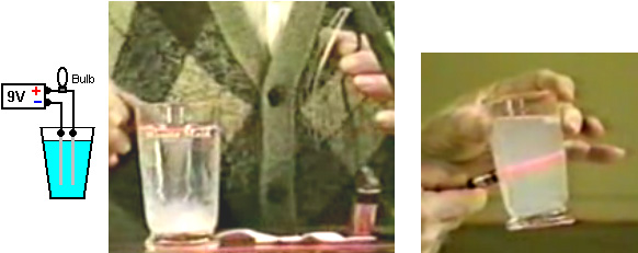 Finance: Money only has value when backed by something of worth. The largest purchase that most people make is buying a property. This is often done by taking out a mortgage with a financial institution such as a bank or a Building Society. For this, most people sign a mortgage agreement with the bank, agreeing to pay back the mortgage amount plus a large amount of interest, generally over a period of many years. If you default on the repayments, typically after many years of payments, the bank takes your property and sells it in order to gain as much money as they can. What you are not told is that the mortgage agreement is a contract and no contract is valid unless something of worth is offered by both parties and full disclosure of all circumstances is made. The bank does not offer anything of value as it just invents the money, creating it out of thin air and without any backing of something of worth. The bank regulations actually forbids the bank from lending out money deposited by it’s members, so a bank cannot legally enter into any such mortgage agreement backed by the funds deposited with it. Further, no contract is valid unless there is a “wet ink” signature by both parties and a wet ink signature can only be made by a human. A bank cannot make a wet ink signature, nor can some other individual sign a contract on behalf of somebody else, so, no mortgage agreement is actually valid in law. Also, the bank being aware of this and not making it clear to you the mortgagee, is in breach of the “full disclosure” requirement of a contract, which is enough to invalidate the contract anyway. Therefore, if a bank tries to take your property for lack of payments, they are acting unlawfully and are not entitled to do so. They usually get away with it, because most people are not aware of the real facts involved. The Media: You are expected to believe that the media is an honest and unbiased source of information. The reality is that all of the main media outlets are owned by just a few, very rich individuals, and their objective is not to provide unbiased reporting. It appears that they have three main objectives. First, they want to make money and objective and truthful reporting does not necessarily help towards that goal. You will never, ever, find honest reporting of anything to do with free-energy or any other positive thing which individuals can do for themselves. For example, if a “report” is made on say, a hydroxy booster to improve mpg and reduce harmful emissions dramatically, it will be arranged that the supposed results show that these thing are not worthwhile. Contrast that with the reality that Dr Scott Cramton can use hydroxy gas to reduce the fuel requirement of any diesel engine by at least 60%. No matter how you try, no major news outlet will every report the honest facts as that could damage the excessive revenue stream of the oil companies. Second, they want to generate as much fear and worry as possible because doing that over an extended period, causes the average person to be more amenable to having their freedoms taken away from them. It facilitates the introduction of surveillance on everybody, identity papers (birth certificate, driving licence, passport, social security number, voting register, National Census record, etc. – very much in the Nazi occupation style), going to war with countries which have never harmed you, considering people to be dishonourable just on the basis of their nationality, and the like. Try counting the items reported in the daily news which are negative – murders, attacks, dishonesty, deaths through accidents, deaths through natural disasters, kidnappings, piracy, violence, environmental damage, etc. and compare that number to the count of positive things reported on – happy events, acts of kindness, successful ventures, etc. and see what ration you get, day after day, after day. This is not just sales being boosted because people love to read about disaster. Instead, it is a deliberate, long-term policy of psychological warfare against ordinary people. Third, they deliberately divert the attention of people away from anything of real importance by promoting and encouraging excessive interest in things of no importance. There is a deliberate dumbing-down of almost all TV programs in the UK, the promotion of excessively violent video games, the promotion of trivia such as celebrities and their activities, dieting, gossip, fashion, and other irrelevant topics. They want you to give all of your attention to these things and not notice what is actually going on all around you. Patrick Kelly http://www.free-energy-info.tuks.nl |