|
There is nothing magic about free-energy and by “free-energy” I mean something which produces output energy without the need for using a fuel which you have to buy. Free energy devices have been around for a very long time now. I have stood beside a water mill and it’s power is scary as it could crush you in moments and never even notice. That mill is on a quietly flowing small river and it can operate at any time day or night without having to pay anything for the power which it uses. It will have cost quite a bit to build the mill in the first place, but after that, it produces major power year after year. Most free-energy devices are just like that as it costs to build them in the first place, but after that they run for free. This presentation is mainly for people who have never come across free-energy and know nothing about it. So, each chapter deals with just one device and tries to explain it clearly. Zach West of the USA can run his 250 cc motorcycle on water. Strictly speaking, he converts the water into gas before feeding it to the engine. All of the components which Zach uses he made himself and none of them are difficult to make. The device used to turn water into gas is called an electrolyser and it operates by passing an electric current through the water. Personally, I suspect that the electric system of a motorcycle is not able to keep the motorcycle battery fully charged while converting water into a suitable fuel, but using a 12-volt system should overcome that difficulty. The method which Zach uses is somewhat unusual as he manages to bleed off and discard most of the oxygen produced when water is converted to gas. This means that the remaining gas is mainly hydrogen which is far less reactive than HHO which is already in the perfect proportions for combination back into water and so is highly reactive. Instead, the resulting gas can be compressed reasonably well, and Zach compresses it to 30 psi (pounds per square inch) in a storage container. This helps with acceleration from stationary at traffic lights. Zach uses a simple, modular style of construction where a series of coiled electrode pairs are each placed inside an individual length of plastic pipe. This is a design which is neither difficult nor particularly expensive to build. In overall broad outline, Zach’s electrolyser is fed water from a water tank to keep it topped up. The electrolyser box contains several pairs of electrodes which split the water into hydrogen and oxygen when fed with pulsed electrical current generated by the electronics, which is powered by the electrical system of the motorcycle. The gas produced by the electrolyser is fed to a bubbler, which prevents any accidental igniting of the gases travelling back to the electrolyser and in addition, removes most of the oxygen from the gas by acting as a gas “separator”. The arrangement is like this:  The hydrogen gas output from the electrolyser is not fed directly to the engine but instead it goes to a pressure tank which is allowed to build up to thirty pounds per square inch pressure before the engine is started. The majority of the oxygen produced by the electrolysis is vented away through a 30 psi one-way valve which is included to keep the pressure inside the bubbler (and the electrolyser) at the 30 psi level. That pressure would be excessive for a high-performance electrolyser which produces HHO which is highly charged electrically and so will ignite spontaneously when compressed, due to it’s own electrical charge. However, in this simple DC electrolyser, the HHO gas is mixed with quite an amount of water vapour which dilutes it and with the reduced oxygen level, that allows compression to thirty pounds per square inch. The water supply system operates by having an air-tight supply tank positioned at a higher level than the electrolyser. A small diameter (1/4” or 6 mm) plastic tube coming from the supply tank feeds through the top of the electrolyser and straight down, terminating at exactly the electrolyte surface level wanted in each of the electrolyser tubes. When the electrolysis lowers the electrolyte level below the bottom of the pipe, bubbles of gas pass up the tube allowing some water to flow from the tank to raise the electrolyte surface level back to it’s wanted position. This is a very neat passive system needing no moving parts, electrical supply or electronics but yet one which accurately controls the electrolyte level. One essential point to understand is that the water tank needs to be rigid so that it will not flex and the filler cap needs to be air-tight to prevent the entire water supply discharging into the electrolyser. Another point to remember when topping up the water tank is that the tank contains HHO gas above the water surface and not just plain air, and that gas mix is at 30 psi pressure. Now, to cover the design in more detail. This 6-volt electrolyser contains eight pairs of electrodes. These electrode pairs are coiled around in “Swiss-roll” style and inserted into a length of 2 inch (50 mm) diameter plastic pipe, ten inches (250 mm) tall. The electrodes are each made from a 10 inch (250 mm) by 5 inch (125 mm) length of 316L-grade stainless steel shimstock which is easy to cut and work. Shimstock is available from a local steel supplier or metal fabrication company and is just a sheet of very thin metal. Each electrode is cleaned carefully, and wearing rubber gloves, cross-scored using coarse sandpaper in order to produce a very large number of microscopic mountain peaks on the surface of the metal. This increases the surface area and provides a surface which makes it easier for gas bubbles to break away from and rise to the surface of the electrolyte. The electrodes are rinsed off with clean water and then coiled round, using spacers to maintain the necessary inter-plate gap, to form the required shape which is then inserted into a length of plastic pipe as shown here:  As the springy metal pushes outwards in an attempt to straighten up again, spacers are used to keep the electrodes evenly separated along their whole length by inserting 1/8 inch (3 mm) thick vertical spacer strips. The connections to the plates are made by drilling a hole in the corner of the plate and inserting the wire several times through the hole, twisting it back around itself and making a wire-to-wire solder joint on both sides of the steel. The joint is then insulated with silicone or any other suitable material. It is, of course, essential that the joint does not short-circuit to the other electrode even though that electrode is very close by.  It is always difficult to make a good electrical connection to stainless steel plates if space is restricted as it is here. In this instance, the electrical wire is wrapped tightly through a drilled hole and then soldered and insulated. The soldering is only on the wire as solder will not attach to stainless steel. An unusual feature of this design is that each of the electrode pairs is effectively a separate electrolyser in its own right as it is capped top and bottom, and effectively physically isolated from the other electrodes. The water feed comes through the top cap which has a hole drilled in it to allow the gas to escape. The electrical wires (#12 AWG or swg 14) are fed through the base and sealed against leakage of electrolyte. Each of these units has some electrolyte stored above it, so there is no chance of any part of the electrode surface not being able to generate gas. There is also a large amount of freeboard to contain splashes and sloshing without any electrolyte being able to escape from the container. The end caps are standard PVC caps available from the supplier of the PVC piping, as is the PVC glue used to seal them to the pipe. Eight of these electrodes are placed in a simple electrolyser case and connected together in pairs as shown here:  Pairs of pipe-enclosed electrode spirals are then connected in a chain inside the electrolyser as shown here:  Many years of experimentation and testing have shown that 316L-grade stainless steel is the most suitable material for electrodes, but surprisingly, stainless steel is not highly electrically conductive as you would expect. Each electrode causes a voltage drop of nearly half a volt, and so careful surface preparation, cleansing and conditioning are needed to get top performance from the electrodes. This process is described in detail by the very experienced Bob Boyce who says: The preparation of the plates is one of the most important steps in producing an electrolyser which works well. This is a long task, but it is vital that it is not skimped or hurried in any way. Surprisingly, brand new shiny stainless steel is not particularly suitable for use in an electrolyser and it needs to receive careful treatment and preparation before it will produce the expected level of gas output. The first step is to treat both surfaces of every plate to encourage gas bubbles to break away from the surface of the plate. This could be done by grit blasting, but if that method is chosen, great care must be taken that the grit used does not contaminate the plates. Stainless steel is not cheap and if you get grit blasting wrong, then the plates will be useless as far as electrolysis is concerned. A safe method is to score the plate surface with coarse sandpaper. This is done in two different directions to produce a cross-hatch pattern. This produces microscopic sharp peaks and valleys on the surface of the plate and those sharp points and ridges are ideal for helping bubbles to form and break free of the plate.  When doing hand sanding the sandpaper is drawn across the plates in one direction only and not backwards and forwards, as the backwards stroke always destroys the perfectly good ridges created on the forward stroke. Also, you only need two strokes in one direction before turning the plate through ninety degrees and completing the sanding of that face of the plate with just two more strokes (again, with no backstroke). Always wear rubber gloves when handling the plates to avoid getting finger marks on the plates. Wearing these gloves is very important as the plates must be kept as clean and as grease-free as possible, ready for the next stages of their preparation. Any particles created by the sanding process should now be washed off the plates. This can be done with clean tap water (not city water though, due to all the chlorine and other chemicals added), but only use distilled water for the final rinse. While Potassium hydroxide (KOH) and Sodium hydroxide (NaOH) are the very best electrolytes, they need to be treated with care. The handling for each is the same: Always store it in a sturdy air-tight container which is clearly labelled "DANGER! - Potassium Hydroxide". Keep the container in a safe place, where it can’t be reached by children, pets or people who won't take any notice of the label. If your supply of KOH is delivered in a strong plastic bag, then once you open the bag, you should transfer all its contents to sturdy, air-tight, plastic storage containers, which you can open and close without risking spilling the contents. Hardware stores sell large plastic buckets with air tight lids that can be used for this purpose. When working with dry KOH flakes or granules, wear safety goggles, rubber gloves, a long sleeved shirt, socks and long trousers. Also, don’t wear your favourite clothes when handling KOH solution as it is not the best thing to get on clothes. It is also no harm to wear a face mask which covers your mouth and nose. If you are mixing solid KOH with water, always add the KOH to the water, and not the other way round, and use a plastic container for the mixing, preferably one which has double the capacity of the finished mixture. The mixing should be done in a well-ventilated area which is not draughty as air currents can blow the dry KOH around. When mixing the electrolyte, never use warm water. The water should be cool because the chemical reaction between the water and the KOH generates a good deal of heat. If possible, place the mixing container in a larger container filled with cold water, as that will help to keep the temperature down, and if your mixture should “boil over” it will contain the spillage. Add only a small amount of KOH at a time, stirring continuously, and if you stop stirring for any reason, put the lids back on all containers. If, in spite of all precautions, you get some KOH solution on your skin, wash it off with plenty of running cold water and apply some vinegar to the skin. Vinegar is acidic, and will help balance out the alkalinity of the KOH. You can use lemon juice if you don't have vinegar to hand - but it is always recommended to keep a bottle of vinegar handy. Plate cleansing is always done with NaOH. Prepare a 5% to 10% (by weight) NaOH solution and let it cool down. A 5% solution ‘by weight’ is 50 grams of NaOH in 950 cc of water. A 10% solution ‘by weight’ is 100 grams of NaOH in 900 cc of water. As mentioned before, never handle the plates with your bare hands, but always use clean rubber gloves. A voltage is now applied across the whole set of plates by attaching the leads to the outermost two plates. This voltage should be at least 2 volts per cell, but it should not exceed 2.5 volts per cell. Maintain this voltage across the set of plates for several hours at a time. The current is likely to be 4 amps or more. As this process continues, the boiling action will loosen particles from the pores and surfaces of the metal. This process produces HHO gas, so it is very important that the gas is not allowed to collect anywhere indoors (such as on ceilings). After several hours, disconnect the electrical supply and pour the electrolyte solution into a container. Rinse out the cells thoroughly with distilled water. Filter the dilute NaOH solution through paper towels or coffee filters to remove the particles. Pour the dilute solution back into the cells and repeat this cleaning process. You may have to repeat the electrolysis and rinsing process many times before the plates stop putting out particles into the solution. If you wish, you can use a new NaOH solution each time you cleanse, but please understand that you can go through a lot of solution just in this cleaning stage if you choose to do it that way. When cleansing is finished (typically 3 days of cleansing), do a final rinse with clean distilled water. It is very important that during cleansing, during conditioning and during use, that the polarity of the electrical power is always the same. In other words, don’t swap the battery connections over as that destroys all the preparation work and requires the cleansing and conditioning processes to be carried out all over again. Using the same concentration of solution as in cleansing, fill the cells with dilute solution. Apply about 2 volts per cell and allow the unit to run. Remember that very good ventilation is essential during this process. As water is consumed, the levels will drop. Once the cells stabilise, monitor the current draw. If the current draw is fairly stable, continue with this conditioning phase continuously for two to three days, adding just enough distilled water to replace what is consumed. If the solution changes colour or develops a layer of crud on the surface of the electrolyte, then the electrodes need more cleansing stages. After two to three days of run time, pour out the dilute KOH solution and rinse out the cells thoroughly with distilled water. The construction which Zach has used is very sensible, utilising readily available, low-cost PVC piping. The spiral electrodes are inside 2” diameter pipe and Zach says that the bubbler is also 2” diameter PVC pipe. I seriously doubt that a two-inch diameter bubbler could handle a flow as high as 17 lpm which is a substantial amount. Also. You want the bubbles in the bubbler to be small in order that the gas comes into good contact with the water. Consequently, using more than one bubbler where the diagram shows just one, would be sensible. The bubbler is located between the storage tank and the engine and positioned as close to the engine as possible. The bubbler does two things, most importantly, it prevents the gas in the storage tank being ignited by a backfire caused by an engine valve sticking slightly open and secondly, it removes every last trace of potassium hydroxide fumes from the gas, protecting the life of the engine. This is a big gain for such a simple addition. The gas storage tank is also made from PVC pipe, this time, 4 inch (100 mm) diameter, 14 inches (350 mm) long with standard end caps fixed in place with PVC glue as shown below. This is a compact and effective arrangement well suited for use on a motorcycle. The majority of this extra equipment can be mounted in bike panniers, which is a neat arrangement.  The electric drive to the electrolyser is from a Pulse Width Modulator (also known as a “DC Motor-speed controller”) which was bought from the Hydrogen Garage in America. That particular PWM board is no longer available, so especially for those people in Europe the choice might be rmcybernetics.com, although there are many suppliers and the module should not be expensive. 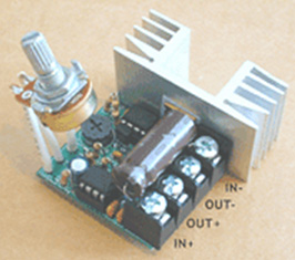 As this unit was rated at just 15 Amps maximum, Zach added another 15 Amp rated FET transistor in parallel to the output stage to raise the current capacity to 30 Amps. A fuse protects against accidental short circuits and a relay is used to control when the electrolyser is to be producing gas. The connecting wire is #12 AWG (swg 14) which has a maximum continuous current capacity of just under ten amps, so although the current peaks may be twenty amps, the average current is much lower than that. Two electromagnets outside the bubbler, positioned 2.5 inches (65 mm) above the base, are connected as part of the electrical supply to the electrolyser, and these cause most of the oxygen and hydrogen bubbles to separate and exit the bubbler through different pipes. There is a divider across the bubbler to assist in keeping the gases from mixing again above the water surface. The bubbler also washes most of the potassium hydroxide fumes out of the gas as the bubbles rise to the surface, protecting the engine as these fumes have a very destructive effect on engines. The objective with any HHO system is to have the minimum amount of gas between the bubbler and the engine in order to block the ignition of the gas in the unlikely event of a backfire. In this system, the gas storage tank contains a very large amount of gas, though admittedly it is not full HHO gas thanks to the electromagnet separation system, but nevertheless, it would be most advisable to have a second bubbler between the gas storage tank and the engine, positioned as close to the engine as possible. HHO gas produces a very high-speed shock-wave when it is ignited so the bubbler needs to be of strong construction to withstand this. No pop-off bubbler cap or blow-out device acts fast enough to contain a HHO shock-wave, so make the bubbler housing strong enough to withstand the pressure wave. Zach’s electrolyser arrangement is like this:  It must be realised that the water tank, electrolyser, bubbler/separator and hydrogen holding tank, all operate at thirty pounds per square inch. This means that each of these containers must be robust enough to withstand that pressure quite easily. It also means that the 30 psi one-way check valve on the oxygen venting pipe is an essential part of the design as well as being a safety feature. As a bubble of gas from the electrolyser escapes into the water tank every time a drop of water feeds to the electrolyser, the contents of the water tank above the water surface becomes a stronger and stronger mix of air and HHO gas. Consequently, it soon becomes an energetic mixture. It is common for static electricity to build up on a tank of this nature, so it will be very important to earth both the tank and it’s cap before removing the cap to top up the tank with more water. The electrolyser has a potassium hydroxide (KOH) solution in it. The electrolysis process produces a mixture of hydrogen, oxygen, dissolved gases (air) and potassium hydroxide fumes. When the system is being used, the water in the bubbler washes out most of the potassium hydroxide fumes, and in doing so, it gradually becomes a dilute electrolyte itself. Potassium hydroxide is a true catalyst and while it promotes the electrolysis process, it does not get used up during electrolysis. The only loss is to the bubbler. Standard practice is to pour the contents of the bubbler into the electrolyser from time to time, filling the bubbler again with fresh water. Potassium hydroxide has been found to be the most effective catalyst for electrolysis but it has a very bad effect on the engine if it is allowed to enter it. The first bubbler is very effective in removing the potassium hydroxide fumes, but many people prefer to take the scrubbing process a step further by placing a second bubbler in the line, in this instance, between the hydrogen pressure tank and the engine. With two bubblers, absolutely no potassium hydroxide fumes reach the engine. When running with HHO gas as the only fuel, it is essential to adjust the timing of the spark so that it occurs after Top Dead Centre. The timing on this bike is now set at 8 degrees after TDC. However, if David Quirey’s style of bubbling the HHO through a liquid such as acetone, then no timing alterations would be needed. This electrolyser is designed to run off the nominal six volts of a motorcycle electrics (about 7.3 volts with the engine running), but increasing the number of tubes, each containing electrode coils, would convert the design to a 12V system and then the electrolyser housing would probably be like this:  It is possible that seven sets of three or four spirals wired in parallel would be used for larger engines with their 13.8 volt electric systems. Zach uses the very simple method of allowing excess gas to be vented via the oxygen valve if gas production exceeds the requirements of the engine. When operating on a twelve volt system it might be more convenient to use a standard pressure switch which opens an electrical connection when the gas pressure rises above the value for that switch: 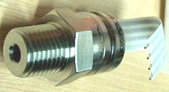 The pressure switch just mounts on one of the end caps of the pressure tank and the switch electrical connection is placed between the relay and the electrolyser. If the gas pressure reaches it’s maximum value of 30 psi. then the switch opens, stopping electrolysis until the pressure drops again:  Caution: This electrolyser is not a toy. If you make and use one of these, you do so entirely at your own risk. Neither the designer of the electrolyser, the author of this document or the provider of the internet display are in any way liable should you suffer any loss or damage through your own actions. While it is believed to be entirely safe to make and use an electrolyser of this design, provided that the safety instructions shown below are followed, it is stressed that the responsibility is yours and yours alone. An electrolyser should not be considered as an isolated device. You need to remember that both electrical and gas safety devices are an essential part of any such installation. The electrical safety devices are a circuit-breaker (as used by any electrician when wiring a house) to protect against accidental short-circuits, and a relay to make sure that the booster does not operate when the engine is not running:  However, the system designed by Zach West is almost certainly not self-sustaining and if that is correct, then the battery powering the electrolyser will need to be charged between trips. That does not have to be the situation as high-efficiency electrolysers are available. First, the Shigeta Hasebe spiral plate electrolyser has produced 7 lpm of HHO gas mix for an input of just 84 watts and while that 84 watts is an inconvenient 2.8V at 30 amps, it should be possible to raise the voltage and lower the current without losing too much of the performance. In my opinion, the electrics of a motorcycle should be able to output 84 watts and so the motorcycle could become self-powered. Motorcycles can definitely become self-powered as can be seen from the electric motorcycle system of Teruo Kawai’s COP>3 design. Teruo went to America and was in a meeting aimed at getting his design manufactured and sold in America when the meeting was interrupted and Teruo intimidated into abandoning his venture. You must also remember that Steve Ryan of New Zealand demonstrated running his motorcycle on treated water. I suspect that the treated water was water which had been infused by charged water clusters as described by Suratt and Gourley. Their electrolyser has an efficiency of 0.00028 kilowatt-hour or less to generate one litre of gas. Those inconvenient units mean that to produce 1 lpm needs 16.8 watts or 7 lpm needs 118 watts. If cold water mist is added to the air entering the motorcycle engine, then it seems likely that a good deal less than 7 lpm would be needed. If you have a good enough tank which is made of a material capable of containing the very small molecules of this gas, then the gas can be compressed to 1000 psi and that should allow a motorcycle to run for some time on the gas cylinder. Patrick Kelly http://www.free-energy-info.com http://www.free-energy-info.tuks.nl |