|
Where the objective is to produce electricity from a rotating magnetic field, there has always been a search for some method of either reducing, or eliminating altogether, the drag on the rotor when electric current is drawn from the coils. One design which claims to have very limited drag caused by current draw is the Kromrey design. The main characteristics of this design are said to be: 1. It has almost constant electrical power output even when the rotor speed is altered by as much as 35%. 2. It can continue to operate with it's electrical output short-circuited, without heating the rotor or causing a braking effect. 3.. The production efficiency (electrical output divided by the driving force) is high. 4. The frequency of it's AC output power can be adjusted to that required by the equipment which it powers. 5. The rotor can be spun at any rate from 800 rpm to 1,600 rpm. 6. The simple construction allows manufacturing costs to be about 30% less than other generators. 7. This generator is recommended for supplying power at or above the 1 kilowatt level. Here is the patent for this device: My present invention relates to an electric generator which converts magnetic energy into electric energy using two components which can rotate relative to each other, i.e. a stator and a rotor, one having electromagnets or permanent magnets which induce a voltage in a winding which forms part of an output circuit mounted on the other component. Conventional generators of this type use a winding which whose conductors form loops in different axial planes so that opposite parts of each loop pass through the field of each pole pair, twice per revolution. If the loops are open circuit, then no current flows in the winding and no reaction torque is developed, leaving the rotor free to turn at the maximum speed of its driving unit. As soon as the output winding is connected across a load or is short-circuited, the resulting current flow tends to retard the motion of the rotor to an extent which depends on the intensity of the current and this makes it necessary to include compensating speed-regulating devices if it is necessary to maintain a reasonably constant output voltage. Also, the variable reaction torque subjects the rotor and its transmission to considerable mechanical stresses and possible damage. It is therefore the general object of this invention to provide an electric generator which has none of the above disadvantages. Another object is to provide a generator whose rotor speed varies very little in speed between open circuit operation and current delivery operation. Another objective is to provide a generator whose output voltage is not greatly affected by fluctuations in its rotor speed. I have found that these objectives can be achieved by rotating an elongated ferromagnetic element, such as a bar-shaped soft-iron armature, and a pair of pole pieces which create an air gap containing a magnetic field. Each of the outer extremities of the armature carries a winding, ideally, these windings are connected in series, and these coils form part of a power output circuit used to drive a load. As the armature rotates relative to the air gap, the magnetic circuit is intermittently completed and the armature experiences periodic remagnetisations with successive reversals of polarity. When the output circuit is open, the mechanical energy applied to the rotor (less a small amount needed to overcome the friction of the rotating shaft) is absorbed by the work of magnetisation, which in turn, is dissipated as heat. In actual practice however, the resulting rise in temperature of the armature is hardly noticeable, particularly if the armature is part of the continuously air-cooled rotor assembly. When the output circuit is closed, part of this work is converted into electrical energy as the current flow through the winding opposes the magnetising action of the field and increases the apparent magnetic reluctance of the armature, and so the speed of the generator remains substantially unchanged if the output circuit is open or closed. As the armature approaches its position of alignment with the gap, the constant magnetic field tends to accelerate the rotation of the armature, aiding the applied driving force. After the armature passes through the gap there is a retarding effect. When the rotor picks up speed, the flywheel effect of its mass overcomes these fluctuations in the applied torque and a smooth rotation is experienced. In a practical embodiment of this invention, the magnetic flux path includes two axially spaced magnetic fields traversing the rotor axis and substantially at right angles to it. These fields are generated by respective pole pairs co-operating with two axially spaced armatures of the type already described. It is convenient to arrange these two armatures so that they lie in a common axial plane and similarly, the two field-producing pole pairs also lie in a single plane. The armatures should be laminated to minimise eddy currents, so they are made of highly permeable (typically, soft-iron) foils whose principle dimension is perpendicular to the rotor axis. The foils can be held together by rivets or any other suitable method. If the ferromagnetic elements are part of the rotor, then the output circuit will include the usual current-collecting means, such as slip-rings or commutator segments, depending on whether AC or DC current output is desired. The source of coercive force in the stator includes, advantageously, a pair of oppositely positioned, yoke-shaped magnets of the permanent or electrically energised type, whose extremities constitute the pole pieces mentioned above. If electromagnets are used in the magnetic circuit, then they may be energised by an external source or by direct current from the output circuit of the generator itself. I have found that the terminal voltage of the output circuit does not vary proportionately to the rotor speed as might be expected, but instead, it drops at a considerably slower rate with decreasing rotor speed. So, in a particular tested unit, this voltage fell to only about half its original value when the rotor speed was dropped to one third. This non-linear relationship between terminal voltage and driving rate produces a substantially constant load current and therefore, electric output over a wide speed range, at least under certain load conditions, inasmuch as the inductive reactance of the winding is proportional to frequency (and consequently, to rotor speed) so as to drop off more rapidly than the terminal voltage, in the event of a speed reduction, with a resulting improvement in the power factor of the load circuit. If the magnetic circuit contains only a single pole pair per air gap, the flux induced in the rotating armature will change its direction twice per revolution so that each revolution produces one complete cycle of 360 electrical degrees. In general, the number of electrical degrees per revolution will equal 360 times the number of pole pairs, it being apparent that this number ought to be odd since with even numbers it would not be possible to have poles alternating in polarity along the path of the armature and at the same time to have the North and South poles of each pair at diametrically opposite locations. In any case, it is important to dimension the curved facing faces of the pole pairs in such a manner so as to avoid allowing the armature to bridge between adjoining poles, so it is necessary to make the sum of the arcs spanned by these faces (in the plane of rotation) equal to considerably less than 360 degrees electrical. The invention will now be described in more detail, reference being made to the accompanying drawings in which: 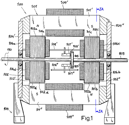 Fig.1 and Fig1A. illustrate a first embodiment of my invention, shown in axial section and in a cross-sectional view taken on line IA - IA of Fig.1 respectively. 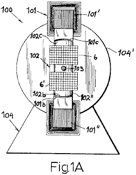 Fig.2 and Fig.3 are perspective views illustrating two other embodiments.   Fig.4 and Fig.5 illustrate diagrammatically, two output circuit arrangements, one for a DC output and one for an AC output. 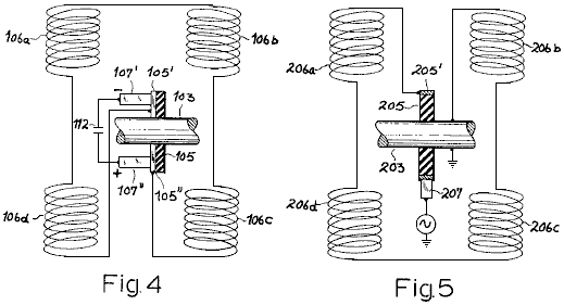 Fig.6 is a somewhat diagrammatic illustration of an arrangement for comparing the outputs of a conventional generator and a generator according to this invention.  The generator 100 shown in Fig.1 and Fig.1A comprises a stator 101 and a rotor 102 which has a pair of laminated armatures 102' and 102", carried on a shaft 103 which is free to rotate in bearings mounted in the end plates 104' and 104", of a generator housing 104 which is made from non-magnetic material (e.g. aluminium) which is rigidly attached to the stator.  Shaft 103 is coupled to a source of driving power indicated diagrammatically by an arrow 110. The stator 101 includes a pair of yoke-shaped laminated electromagnets 101' and 101" whose extremities form two pairs of co-planar pole pieces, designated respectively 101a, 101b (North magnetic pole) and 101c, 101d (South magnetic pole). The pole pieces have concave faces, facing towards the complimentary convex faces 102a, 102d of armature 102' and 102b, 102c of armature 102". These faces whose concavities are all centred on the axis of shaft 103, extend over arcs of approximately 20O to 25O each in the plane of rotation (Fig.1A) so that the sum of these arcs adds up to about 90O geometrically and electrically. 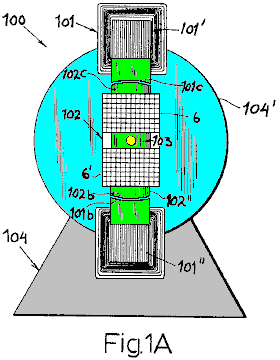 The stator magnets 101', 101" are surrounded by energising windings 109', 109" which are connected across a suitable source of constant direct current (not shown). Similar windings, each composed of two series-connected coils 106a, 106d and 106b, 106c, surround the rotor armatures 102' and 102", respectively. These coils form part of an output circuit which further includes a pair of brushes 107', 107" which are carried by arms 108', 108" on housing 104 with mutual insulation brushes 107', 107" co-operate with a pair of commuter segments 105', 105" (see also Fig.4) which are supported by a disc of insulating material 105, mounted on shaft 103. 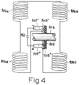 By virtue of the series-connection of coils 106a-106d between the segments 105' and 105", as illustrated in Fig.4, the alternating voltage induced in these coils gives rise to a rectified output voltage at brushes 107' and 107". The unidirectional current delivered by these brushes to a load (not shown) may be smoothed by conventional means, represented by capacitor 112 in Fig.4. 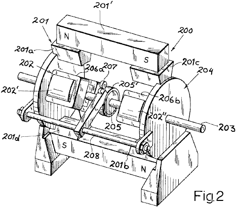 Fig.2, shows a modified generator 200, whose housing 204, supports a stator 201 essentially consisting of two permanent bar magnets 201' and 201", extending parallel to the drive shaft 203 (on opposite side of it), each of these magnets being rigid and each having a pair of sole shoes 201a, 201c and 201b, 201d respectively. Rotor 202 is a pair of laminated armatures 202' and 202",similar to those of the previous embodiment, whose output coils 206a, 206b, 206c and 206d are serially connected between a slip-ring 205', supported on shaft 203 through the intermediary of an insulating disc 205, and another terminal here represented by the grounded shaft 203 itself. Slip-ring 205' is contacted by brush 207 on holder 208, the output of this brush being an alternating current of a frequency determined by the rotor speed. 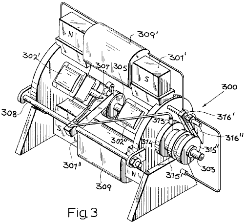 Fig.3 shows a generator 300 which is basically similar to the generator 100 shown in Fig.1 and Fig.1A. It's shaft 303 carries a pair of laminated soft-iron armatures 302', 302" which can rotate in the air gaps of a pair of electromagnets 301', 301" which have windings 309' and 309". The commutator 305 again co-operates with a pair of brushes 307, only one of which is visible in Fig.3. This brush, carried on an arm 308, is electrically connected to a brush 313 which engages with a slip-ring 314 positioned on an extremity of shaft 303 which also carries two further slip-rings 315', 315" which are in conductive contact with ring 314 but are insulated from the shaft. Two further brushes 316', 316" contact the rings 315', 315" and respectively are connected to windings 309' and 309". The other ends of these windings are connected to an analogous system of brushes and slip-rings on the extremity of the opposite shaft, and arranged so that the two commutator brushes are effectively bridged across the windings 309' and 309" in parallel. Therefore, in this embodiment, the stator magnets are energised from the generator output itself, it being understood that the magnets 301' and 301" (made, for example, of steel rather than soft iron) will have a residual coercive force sufficient to induce an initial output voltage. Naturally, the circuits leading from the brushes 307 to the windings 309', 309" may include filtering as described in connection with Fig.4. 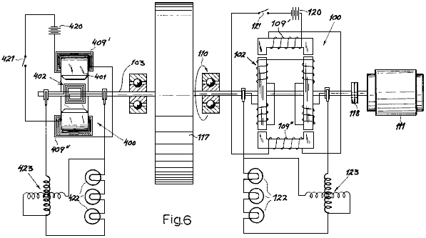 Fig.6 shows a test circuit designed to compare the outputs of a generator of this design, such as the unit 100 of Fig.1 and Fig.1A, with a conventional generator 400 of the type having a looped armature 402 which rotates in the gap of a stator magnet 401 which is fitted with energising windings 409', 409". The two generators are interconnected by a common shaft 103 which carries a flywheel 117. This shaft is coupled through a clutch 118 to a drive motor 111 which drives the rotors 402 and 102 of both generators in unison, as indicated by arrow 110. Two batteries 120 and 420, in series with switches 121 and 421, represent the method of supplying direct current to the stator windings 109', 109" and 409', 409" of the two generators. The rectified output of generator 100 is delivered to a load 122, shown here as three incandescent lamps connected in series, and with a combined consumption of 500 watts. Generator 400, provides current into an identical load 422. Two watt meters 123 and 423 have their voltage and current windings connected respectively in shunt and in series with their associated loads 122 and 422, to measure the electric power delivered by each generator. When clutch 118 is engaged, shaft 113 with it's flywheel 117 is brought to an initial driving speed of 1,200 rpm. at which point, the switch 421 in the energising circuit of the conventional generator 400, is closed. The lamps 422 light immediately and the corresponding wattmeter 423 shows an initial output of 500 watts. However, this output drops immediately as the flywheel 117 is decelerated by the braking effect of the magnetic field on armature 402. Next, the procedure is repeated but with switch 421 open and switch 121 closed. This energises generator 100 and the lamps 122 light up, wattmeter 123 showing an output of 500 watts, which remains constant for an indefinite period of time , there being no appreciable deceleration of flywheel 117. When the clutch 118 is released and the rotor speed gradually decreases, the output of generator 100 is still substantially 500 watts at a speed of 900 rpm. and remains as high as 360 watts when the speed dropped further to 600 rpm. In a similar test with a generator of the permanent magnet type, such as the one shown at 200 in Fig.2, a substantially constant output was observed over a range of 1600 to 640 rpm. Patrick Kelly http://www.free-energy-info.com http://www.free-energy-devices.com http://www.free-energy-info.tuks.nl |