|
There is nothing magic about free-energy and by “free-energy” I mean something which produces output energy without the need for using a fuel which you have to buy.  Donald Lee Smith died a few years ago. He is famous for his high-power self-powered free energy designs. There are several videos on the web, showing some of his lectures. He produced one pdf document which is shown at the end of this chapter, and in May 2004 he was granted one patent. Don stated clearly in one of his lectures, that he never did disclose the full details of his designs. However, Don says that he discloses enough for somebody who is experienced in radio-frequency electronics to be able to deduce the things which he does not disclose and so build a device for his own use. If that is the case, then anybody who has succeeded in doing so has kept very quiet about it afterwards (which would be understandable). Don produced at least forty eight different devices which draw energy from what Don prefers to call "the ambient background". His devices are capable of supplying kilowatts of excess energy and in most cases they do not require any input energy to be supplied by the user. Don’s work is subtle and not easy to replicate. It is based on the principle that the power output of a circuit increases with the square of the frequency and the square of the voltage. So, if you double the frequency and double the voltage, then the output power goes up and becomes sixteen times greater. As a result of this, Don’s best known design uses a Neon Sign Transformer circuit which raises the frequency to around 35,000 cycles per second and raises the voltage to anything from 2,000 volts to 12,000 volts, giving a power output is physically quite small and yet it has an output of 160 kilowatts (8000 volts at 20 amps) from an input of 12 volts 1 amp. That is, the output power is more than thirteen thousand times greater than the input power. Consequently, his designs are dangerous and can kill you instantly. In other words, his designs are for experienced developers only. Please bear in mind that the voltages here and their associated power levels are literally lethal and perfectly capable of killing anyone who handles the device carelessly when it is powered up. When a replication of this device is ready for routine use, it must be encased so that none of the high-voltage connections can be touched by anyone. This is not a suggestion, but it is a mandatory requirement, despite the fact that the components shown in the photographs are laid out in what would be a most dangerous fashion were the circuit to be powered up as it stands. Under no circumstances, construct and test this circuit unless you are already experienced in the use of high-voltage circuits or can be supervised by somebody who is experienced in this field. This is a "one hand in the pocket at all times" type of circuit and it needs to be treated with great care and respect at all times, so be sensible. Don Smith considered himself to be self taught. Don says that his understanding comes from the work of Nikola Tesla as recorded in Thomas C. Martin's book "The Inventions, Researches, and Writings of Nikola Tesla" ISBN 0-7873-0582-0. This book can be downloaded from www.free-energy-info.com as a pdf file. Don states that he repeated each of the experiments found in the book and that gave him his understanding of what he prefers to describe as the 'ambient background energy' which is also called the 'zero-point energy field'. Don remarks that he advanced further than Tesla in this field, partly because of the devices now available to him and which were not available when Tesla was alive. Don stresses two key points. Firstly, a dipole can cause a disturbance in the magnetic component of the 'ambient background' and that imbalance allows you to collect large amounts of electrical power, using capacitors and inductors (coils). Secondly, you can pick up as many powerful electrical outputs as you want from that one magnetic disturbance, without depleting the magnetic disturbance in any way. This allows massively more power output than the small power needed to create the magnetic disturbance in the first place. This is what produces a “Coefficient Of Performance”>1 device and Don has created nearly fifty different devices based on that understanding. Although they get removed quite frequently, there is one video which is definitely worth watching if it is still there. It is located at www.metacafe.com and was recorded in 2006. It covers a good deal of what Don has done. In the video, reference is made to Don's website but you will find that it has been taken over by Big Oil who have filled it with innocuous similar-sounding things of no consequence, apparently intended to confuse newcomers searching for information on Don’s designs. The present situation in 2019 is that few people understand Don’s designs fully (and I myself, fall into that category), the high-voltage components are expensive and hard to find, and the high voltages are dangerous. However, we will look at three of his many designs and try to understand them as best we can. We will start with his patented design: TRANSFORMER GENERATOR MAGNETIC RESONANCE INTO ELECTRIC ENERGY ABSTRACT The present invention refers to an Electromagnetic Dipole Device and Method, where wasted radiated energy is transformed into useful energy. A Dipole as seen in Antenna Systems is adapted for use with capacitor plates in such a way that the Heaviside Current Component becomes a useful source of electrical energy. DESCRIPTION Technical Field: This invention relates to loaded Dipole Antenna Systems and their Electromagnetic radiation. When used as a transformer with an appropriate energy collector system, it becomes a transformer/generator. The invention collects and converts energy which is radiated and wasted by conventional devices. Background Art: A search of the International Patent Database for closely related methods did not reveal any prior art with an interest in conserving radiated and wasted magnetic waves as useful energy. DISCLOSURE OF THE INVENTION The invention is a new and useful departure from transformer generator construction, such that radiated and wasted magnetic energy changes into useful electrical energy. Gauss meters show that much energy from conventional electromagnetic devices is radiated into the ambient background and wasted. In the case of conventional transformer generators, a radical change in the physical construction allows better access to the energy available. It is found that creating a dipole and inserting capacitor plates at right angles to the current flow, allows magnetic waves to change back into useful electrical (coulombs) energy. Magnetic waves passing through the capacitor plates do not degrade and the full impact of the available energy is accessed. One, or as many sets of capacitor plates as is desired, may be used. Each set makes an exact copy of the full force and effect of the energy present in the magnetic waves. The originating source is not depleted of degraded as is common in conventional transformers. BRIEF DESCRIPTION OF THE DRAWINGS The Dipole at right angles, allows the magnetic flux surrounding it to intercept the capacitor plate, or plates, at right angles. The electrons present are spun such that the electrical component of each electron is collected by the capacitor plates. Essential parts are the South and North component of an active Dipole. Examples presented here exist as fully functional prototypes and were engineer constructed and fully tested in use by the Inventor. In each of the three examples shown in the drawings, corresponding parts are used.  and S is the South component of the Dipole. Here, 1 marks the Dipole with its North and South components. 2 is a resonant high-voltage induction coil. 3 indicates the position of the electromagnetic wave emission from the Dipole. 4 indicates the position and flow direction of the corresponding Heaviside current component of the energy flow caused by the induction coil 2. 5 is the dielectric separator for the capacitor plates 7. 6 for the purposes of this drawing, indicates a virtual limit for the scope of the electromagnetic wave energy.  In Fig.2A 1 is the hole in the capacitor plates through which the Dipole is inserted and in Fig.2B it is the Dipole with its North and South poles shown. 2 is the resonant high-voltage induction coil surrounding part of the Dipole 1. The dielectric separator 5, is a thin sheet of plastic placed between the two capacitor plates 7, the upper plate being made of aluminium and the lower plate made of copper. Unit 8 is a deep-cycle battery system powering a DC inverter 9 which produces 120 volts at 60 Hz (the US mains supply voltage and frequency, obviously, a 240 volt 50 Hz inverter could be used here just as easily) which is used to power whatever equipment is to be driven by the device. The reference number 10 just indicates connecting wires. Unit 11 is a high-voltage generating device such as a neon transformer with its oscillating power supply.  Fig.3 is a Proof Of Principal Device using a Plasma Tube as an active Dipole. In this drawing, 5 is the plastic sheet dielectric separator of the two plates 7 of the capacitor, the upper plate being aluminium and the lower plate copper. The connecting wires are marked 10 and the plasma tube is designated 15. The plasma tube is four feet long (1.22 m) and six inches (100 mm) in diameter. The high-voltage energy source for the active plasma dipole is marked 16 and there is a connector box 17 shown as that is a convenient method of connecting to the capacitor plates when running tests on the device.  Fig.4 shows a Manufacturer's Prototype, constructed and fully tested. 1 is a metal Dipole rod and 2 the resonant high-voltage induction coil, connected through wires 10 to connector block 17 which facilitates the connection of it's high-voltage power supply. Clamps 18 hold the upper edge of the capacitor packet in place and 19 is the base plate with it's supporting brackets which hold the whole device in place. 20 is a housing which contains the capacitor plates and 21 is the point at which the power output from the capacitor plates is drawn off and fed to the DC inverter. BEST METHOD OF CARRYING OUT THE INVENTION The invention is applicable to any and all electrical energy requirements. The small size and it's high efficiency make it an attractive option, especially for remote areas, homes, office buildings, factories, shopping centres, public places, transportation, water systems, electric trains, boats, ships and 'all things great and small'. The construction materials are commonly available and only moderate skill levels are needed to make the device. CLAIMS 1. Radiated magnetic flux from the Dipole, when intercepted by capacitor plates at right angles, changes into useful electrical energy. 2. A Device and Method for converting for use, normally wasted electromagnetic energy. 3. The Dipole of the Invention is any resonating substance such as Metal Rods, Coils and Plasma Tubes which have interacting Positive and Negative components. 4. The resulting Heaviside current component is changed to useful electrical energy. This patent does not make it clear that the device needs to be tuned and that the tuning is related to its physical location on Earth. The tuning will be accomplished by applying a variable-frequency input signal to the neon transformer and adjusting that input frequency to give the maximum output. The second of Don’s devices to consider is his table-top very high power generator. This is effectively a Tesla Coil system and so the normal electromagnetic effect of the ratio of the number of coil turns does NOT determine the effect between the coils. The demonstration device looks like this:  This device is not the easiest thing in the world to understand. Here is the circuit diagram:  it is probably worth mentioning some of the main points which Don Smith appears to be making. There are some very important points being made here, and grasping these may make a considerable difference to our ability to tap into the excess energy available in our local environment. There are four points worth mentioning: 1. Voltage 2. Frequency 3. Magnetic / Electric relationship 4. Resonance 1. Voltage. We tend to view things with an 'intuitive' view, generally based on fairly simple concepts. For example, we automatically think that it is more difficult to pick up a heavy object than to pick up a light one. How much more difficult? Well, if it is twice as heavy, it would probably be about twice as much effort to pick it up. This view has developed from our experience of things which we have done in the past, rather than on any mathematical calculation or formula. Well, how about pulsing an electronic system with a voltage? How would the output power of a system be affected by increasing the voltage? Our initial 'off-the cuff' reaction might be that the power output might be increased a bit, but then hold on… we've just remembered that Watts = Volts x Amps, so if you double the voltage, then you would double the power in watts. So we might settle for the notion that if we doubled the voltage then we could double the output power. If we thought that, then we would be wrong. Don Smith points out that as capacitors and coils store energy, if they are involved in the circuit, then the output power is proportional to the square of the voltage used. Double the voltage, and the output power is four times greater. Use three times the voltage and the output power is nine times greater. Use ten times the voltage and the output power is one hundred times greater !  Don says that the energy stored, multiplied by the cycles per second, is the energy being pumped by the system. Capacitors and inductors (coils) temporarily store electrons, and their performance is given by: Capacitor formula: W = 0.5 x C x V2 x Hz where: W is the energy in Joules (Joules = Volts x Amps x seconds) C is the capacitance in Farads V is the voltage Hz is the cycles per second Inductor formula: W = 0.5 x L x A2 x Hz where: W is the energy in Joules L is the inductance in henrys A is the current in amps Hz is the frequency in cycles per second You will notice that where inductors (coils) are involved, then the output power goes up with the square of the current. Double the voltage and double the current gives four times the power output due to the increased voltage and that increased output is increased by a further four times due to the increased current, giving sixteen times the output power. 2. Frequency. You will notice from the formulas above, that the output power is directly proportional to the frequency "Hz". The frequency is the number of cycles per second (or pulses per second) applied to the circuit. This is something which is not intuitive for most people. If you double the rate of pulsing, then you double the power output. When this sinks in, you suddenly see why Nikola Tesla tended to use millions of volts and millions of pulses per second. However, Don Smith states that when a circuit is at it's point of resonance, resistance in the circuit drops to zero and the circuit becomes effectively, a superconductor. The energy for such a system which is in resonance is: Resonant circuit: W = 0.5 x C x V2 x (Hz)2 where: W is the energy in Joules C is the capacitance in Farads V is the voltage Hz is the cycles per second If this is correct, then raising the frequency in a resonating circuit has a massive effect on the power output of the device. The question then arises: why is the mains power in Europe just fifty cycles per second and in America just sixty cycles per second? If power goes up with frequency, then why not feed households at a million cycles per second? One major reason is that it is not easy to make electric motors which can be driven with power delivered at that frequency, so a more suitable frequency is chosen in order to suit the motors in vacuum cleaners, washing machines and other household equipment. However, if we want to extract energy from the environment, then we should go for high voltage and high frequency. Then, when high power has been extracted, if we want a low frequency suited to electric motors, we can pulse the already captured power at that low frequency. It might be speculated that if a device is being driven with sharp pulses which have a very sharply rising leading edge, that the effective frequency of the pulsing is actually determined by the speed of that rising edge, rather than the rate at which the pulses are actually generated. For example, if pulses are being generated at, say, 50 kHz but the pulses have a leading edge which would be suited to a 200 kHz pulse train, then the device might well see the signal as a 200 kHz signal with a 25% Mark/Space ratio, the very suddenness of the applied voltage having a magnetic shocking effect equivalent to a 200 kHz pulse train. 3. Magnetic / Electric relationship. Don states that the reason why our present power systems are so inefficient is because we concentrate on the electric component of electromagnetism. These systems are always COP<1 as electricity is the 'losses' of electromagnetic power. Instead, if you concentrate on the magnetic component, then there is no limit on the electric power which can be extracted from that magnetic component. Contrary to what you might expect, if you install a pick-up system which extracts electrical energy from the magnetic component, you can install any number of other identical pick-ups, each of which extract the same amount of electrical energy from the magnetic input, without loading the magnetic wave in any way. Unlimited electrical output for the 'cost' of creating a single magnetic effect. The magnetic effect which we want to create is a ripple in the zero-point energy field, and ideally, we want to create that effect while using very little power. Creating a dipole with a battery which has a Plus and a Minus terminal or a magnet which has North and South poles, is an easy way to do create an electromagnetic imbalance in the local environment. Pulsing a coil is probably an even better way as the magnetic field reverses rapidly if it is an air-core coil, such as a Tesla Coil. Using a ferromagnetic core to the coil can create a problem as iron can't reverse it's magnetic alignment very rapidly, and ideally, you want pulsing which is at least a thousand times faster than iron can handle.  Don draws attention to the "Transmitter / Receiver" educational kit "Resonant Circuits #10-416" which was supplied by The Science Source, Maine. This kit demonstrated the generation of resonant energy and it's collection with a receiver circuit. However, if several receiver circuits are used, then the energy collected is increased several times without any increase in the transmitted energy. This is similar to a radio transmitter where hundreds of thousands of radio receivers can receive the transmitted signal without loading the transmitter in any way. In Don’s day, this kit was driven by a 1.5 volt battery and lit a 60-watt bulb which was supplied. Not surprisingly, that kit has been discontinued and a trivial kit substituted. If you get the Science Source educational kit, then there are some details which you need to watch out for. The unit has two very nice quality plastic bases and two very neatly wound coils each of 60 turns of 0.47 mm diameter enamelled copper wire on clear acrylic tubes 57 mm (2.25”) in diameter. The winding covers a 28 mm section of the tube. The layout of the transmitter and receiver modules does not match the accompanying instruction sheet and so considerable care needs to be taken when wiring up any of their circuits. The circuit diagrams are not shown, just a wiring diagram, which is not great from an educational point of view. The one relevant circuit is:  Before you buy the kit, it is not mentioned that in order to use it, you now need a signal generator capable of producing a 10-volt signal at 1 MHz. The coil has a DC resistance of just 1.9 ohms but at a 1 MHz resonant frequency, the necessary drive power is quite low. A variable capacitor is mounted on the receiver coil tube, but the one in my kit made absolutely no difference to the frequency tuning, nor was my capacitance meter able to determine any capacitance value for it at all, even though it had no trouble at all in measuring the 101 pF capacitor which was exactly the capacitance printed on it. For that reason, it is shown in blue in the circuit diagram above. Disconnecting it made no difference whatsoever. In this particular kit, standard screw connectors have had one screw replaced with an Allen key headed bolt which has a head large enough to allow finger tightening. Unfortunately, those bolts have a square cut tip where a domed tip is essential if small diameter wires are to be clamped securely. If you get the kit, then I suggest that you replace the connectors with a standard electrical screw connector strip. In tests, the LED lights up when the coils are aligned and within about 100 mm of each other, or if they are close together side by side. This immediately makes the Hubbard device spring to mind. Hubbard has a central "electromagnetic transmitter" surrounded by a ring of "receivers" closely coupled magnetically to the transmitter, each of which will receive a copy of the energy sent by the transmitter:  Don points to an even more clearly demonstrated occurrence of this effect in the Tesla Coil. In a typical Tesla Coil, the primary coil is much larger diameter than the inner secondary coil:  If, for example, 8,000 volts is applied to the primary coil which has four turns, then each turn would have 2,000 volts of potential. Each turn of the primary coil transfers electromagnetic flux to every single turn of the secondary winding, and the secondary coil has a very large number of turns. Massively more power is produced in the secondary coil than was used to energise the primary coil. A common mistake is to believe that a Tesla Coil can't produce serious amperage. If the primary coil is positioned in the middle of the secondary coil as shown, then the amperage generated will be as large as the voltage generated. A low power input to the primary coil can produce kilowatts of usable electrical power. 4. Resonance. An important factor in circuits aimed at tapping external energy is resonance. It can be hard to see where this comes in when it is an electronic circuit which is being considered. However, everything has it's own resonant frequency, whether it is a coil or any other electronic component. When components are connected together to form a circuit, the circuit has an overall resonant frequency. As a simple example, consider a swing:  If the swing is pushed before it reaches the highest point on the mother's side, then the push actually opposes the swinging action. The time of one full swing is the resonant frequency of the swing, and that is determined by the length of the supporting ropes holding the seat and not the weight of the child nor the power with which the child is pushed. Provided that the timing is exactly right, a very small push can get a swing moving in a substantial arc. The key factor is, matching the pulses applied to the swing, that is, to the resonant frequency of the swing. Get it right and a large movement is produced. Get it wrong, and the swing doesn't get going at all (at which point, critics would say "see, see …swings just don't work - this proves it !!"). This principle is demonstrated in the video here. Establishing the exact pulsing rate needed for a resonant circuit is not particularly easy, because the circuit contains coils (which have inductance, capacitance and resistance), capacitors (which have capacitance and a small amount of resistance) and resistors and wires, both of which have resistance and some capacitance. These kinds of circuit are called "LRC" circuits because "L" is the symbol used for inductance, "R" is the symbol used for resistance and "C" is the symbol used for capacitance. Don Smith provides instructions for winding and using the type of air-core coils needed for a Tesla Coil. He says: 1. Decide a frequency and bear in mind, the economy of the size of construction selected. The factors are: (a) Use radio frequency (above 20 kHz). (b) Use natural frequency, i.e. match the coil wire length to the frequency - coils have both capacitance and inductance. (c) Make the wire length either one quarter, one half of the full wavelength. (d) Calculate the wire length in feet as follows: If using one quarter wavelength, then divide 247 by the frequency in MHz. If using one half wavelength, then divide 494 by the frequency in MHz. If using the full wavelength, then divide 998 by the frequency in MHz. For wire lengths in metres: If using one quarter wavelength, then divide 75.29 by the frequency in MHz. If using one half wavelength, then divide 150.57 by the frequency in MHz. If using the full wavelength, then divide 304.19 by the frequency in MHz. 2. Choose the number of turns to be used in the coil when winding it using the wire length just calculated. The number of turns will be governed by the diameter of the tube on which the coil is to be wound. Remember that the ratio of the number of turns in the "L - 1" and "L - 2" coils, controls the overall output voltage. For example, if the voltage applied the large outer coil "L - 1" is 2,400 volts and L - 1 has ten turns, then each turn of L - 1 will have 240 volts dropped across it. This 240 volts of magnetic induction transfers 240 volts of electricity to every turn of wire in the inner "L - 2" coil. If the diameter of L - 2 is small enough to have 100 turns, then the voltage produced will be 24,000 volts. If the diameter of the L - 2 former allows 500 turns, then the output voltage will be 120,000 volts. 3. Choose the length and diameter of the coils. The larger the diameter of the coil, the fewer turns can be made with the wire length and so the coil length will be less, and the output voltage will be lower. 4. For example, if 24.7 MHz is the desired output frequency, then the length of wire, in feet, would be 247 divided by 24.7 which is 10 feet of wire (3,048 mm). The coil may be wound on a standard size of PVC pipe or alternatively, it can be purchased from a supplier - typically, an amateur radio supply store. If the voltage on each turn of L - 1 is arranged to be 24 volts and the desired output voltage 640 volts, then there needs to be 640 / 24 = 26.66 turns on L - 2, wound with the 10 feet of wire already calculated. PJK: At this point, Don's calculations go adrift and he suggests winding 30 turns on a 2-inch former. If you do that, then it will take about 16 feet of wire and the resonant point at 10-feet will be at about 19 turns, giving an output voltage of 458 volts instead of the required 640 volts, unless the number of turns on L1 is reduced to give more than 24 volts per turn. However, the actual required diameter of the coil former (plus one diameter of the wire) is 10 x 12 / (26.67 x 3.14159) = 1.43 inches. You can make this size of former up quite easily if you want to stay with ten turns on the L1 coil. 5. Connect to the start of the coil. To determine the exact resonant point on the coil, a measurement is made. Off-the-shelf multimeters are not responsive to high-frequency signals so a cheap neon is used instead. Holding one wire of the neon in one hand and running the other neon wire along the outside of the L - 2 winding, the point of brightest light is located. Then the neon is moved along that turn to find the brightest point along that turn, and when it is located, a connection is made to the winding at that exact point. L - 2 is now a resonant winding. It is possible to increase the ("Q") effectiveness of the coil by spreading the turns out a bit instead of positioning them so that each turn touches both of the adjacent turns. 6. The input power has been suggested as 2,400 volts. This can be constructed from a Jacob's ladder arrangement or any step-up voltage system. An off-the-shelf module as used with lasers is another option. 7. Construction of the L - 1 input coil has been suggested as having 10 turns. The length of the wire in this coil is not critical. If a 2-inch diameter PVC pipe was used for the L - 2 coil, then the next larger size of PVC pipe can be used for the L - 1 coil former. Cut a 10-turn length of the pipe (probably a 3-inch diameter pipe). The pipe length will depend on the diameter of the insulated wire used to make the winding. Use a good quality multimeter or a specialised LCR meter to measure the capacitance (in Farads) and the inductance (in henrys) of the L - 2 coil. Now, put a capacitor for matching L - 1 to L - 2 across the voltage input of L - 1, and a spark gap connected in parallel is required for the return voltage from L - 1. A trimmer capacitor for L - 1 is desirable. 8. The performance of L - 2 can be further enhanced by attaching an earth connection to the base of the coil. The maximum output voltage will be between the ends of coil L - 2 and lesser voltages can be taken off intermediate points along the coil if that is desirable. This frequency information can be rather hard to understand in the way that Don states it. It may be easier to follow the description given by one developer who says: I have noticed that any machine can be made a super machine just by adding a bipolar capacitor across the coil. Nothing else is needed. With the correct capacitor the coil becomes Naturally Resonant and uses very little Amperage. Each machine uses a different size capacitor. The correct capacitor size can be calculated by dividing the speed of light by the coil's wire length first to get the coil's Natural Frequency and then dividing the voltage to be used by that frequency. The result is the correct size for the capacitor. Your machine will then be very powerful even working from a 12V car battery, no other additions needed. My coil's wire length is 497.333 meters. 299000000 m/sec / 497.333 m = 600000 Hz. 12V / 600000 = 0.00002 or 20 microfarads. A beautiful Naturally Resonant Tank circuit. You can use this with any coil for overunity! Once we have a Naturally Resonant Coil/Capacitor combination we can bring the frequency down to 50 Hz by calculating for the Power Factor Correction: Hz = Resistance x Farads then 50 Hz = R x 0.00002 so 50 / 0.00002 = 2500000 and R = 2500000 or 2.5 Meg Ohms. We then place all three components in parallel and our coil should give us a 50 Hz output. Don provides quite an amount of information on one of his devices shown here: Without his description of the device, it would be difficult to understand it's construction and method of operation. As I understand it, the circuit of what is mounted on this board is as shown here:  This arrangement has bothered some readers recently as they feel that the spark gap should be in series with the L1 coil, like this:  This is understandable, as there is always a tendency to think of the spark gap as being a device which is there to protect against excessive voltages rather than seeing it as an active component of the circuit, a component which is in continuous use. In 1925, Hermann Plauson was granted a patent for a whole series of methods for converting the high voltage produced by a tall aerial system into useable, standard electricity. Hermann starts off by explaining how high voltage can be converted into a convenient form and he uses a Wimshurst static electricity generator as an example of a constant source of high voltage. The output from a rectified Tesla Coil, a Wimshurst machine and a tall aerial are very much alike, and so Hermann's comments are very relevant here. He shows it like this:  Here, the output of the Wimshurst machine is stored in two high-voltage capacitors (Leyden jars) causing a very high voltage to be created across those capacitors. When the voltage is high enough, a spark jumps across the spark gap, causing a massive surge of current through the primary winding of the transformer, which in his case is a step-down transformer as he is aimed at getting a lower output voltage. Don's circuit is almost identical:  Here the high voltage comes from the battery/inverter/neon-tube driver/rectifiers, rather than from a mechanically driven Wimshurst machine. He has the same build up of voltage in a capacitor with a spark gap across the capacitor. The spark gap will fire when the capacitor voltage reaches its designed level. The only difference is in the positioning of the capacitor, which if it matched Hermann's arrangement exactly, would be like this:  which would be a perfectly viable arrangement as far as I can see. You will remember that Tesla, who always speaks very highly of the energy released by the very sharp discharge produced by a spark, shows a high-voltage source feeding a capacitor with the energy passing through a spark gap to the primary winding of a transformer:  However, with Don's arrangement, it can be a little difficult to see why the capacitor is not short-circuited by the very low resistance of the few turns of thick wire forming the L1 coil. Well, it would do that if we were operating with DC, but we are most definitely not doing that as the output from the neon-tube driver circuit is pulsing 35,000 times per second. This causes the DC resistance of the L1 coil to be of almost no consequence and instead, the coil's "impedance" or "reactance" (effectively, it's AC resistance) is what counts. Actually, the capacitor and the L1 coil being connected across each other have a combined "reactance" or resistance to pulsing current at this frequency. This is where the nomograph diagram comes into play, and there is a much easier to understand version of it a few pages later on in this document. So, because of the high pulsing frequency, the L1 coil does not short-circuit the capacitor and if the pulsing frequency matches the resonant frequency of the L1 coil (or a harmonic of that frequency), then the L1 coil will actually have a very high resistance to current flow through it. This is how a crystal set radio receiver tunes in a particular radio station, broadcasting on it's own frequency. Anyway, coming back to Don's device shown in the photograph above, the electrical drive is from a 12-volt battery which is not seen in the photograph. Interestingly, Don remarks that if the length of the wires connecting the battery to the inverter are exactly one quarter of the wave length of the frequency of the oscillating magnetic field generated by the circuit, then the current induced in the battery wires will recharge the battery continuously, even if the battery is supplying power to the circuit at the same time. The battery supplies a small current through a protecting diode, to a standard off-the-shelf "true sine-wave" inverter. An inverter is a device which produces mains-voltage Alternating Current from a DC battery. As Don wants adjustable voltage, he feeds the output from the inverter into a variable transformer called a "Variac" although this is often made as part of the neon-driver circuit to allow the brightness of the neon tube to be adjusted by the user. This arrangement produces an AC output voltage which is adjustable from zero volts up to the full mains voltage (or a little higher, though Don does not want to use a higher voltage). The use of this kind of adjustment usually makes it essential for the inverter to be a true sine-wave type. As the power requirement of the neon-tube driver circuit is so low, the inverter should not cost very much. The neon-tube driver circuit is a standard off-the-shelf device used to drive neon tube displays for commercial establishments. The one used by Don contains an oscillator and a step-up transformer, which together produce an Alternating Current of 9,000 volts at a frequency of 35,100 Hz (sometimes written as 35.1 kHz). The term "Hz" stands for "cycles per second". Don lowers the 9,000 volts as he gets great power output at lower input voltages and the cost of the output capacitors is a significant factor. The particular neon-tube driver circuit which Don is using here, has two separate outputs out of phase with each other, so Don connects them together and uses a blocking diode in each line to prevent either of them affecting the other one. Not easily seen in the photograph, the high-voltage output line has a very small, encapsulated, Gas-Discharge Tube spark gap in it and the line is also earthed. The device looks like this:  Please note that when an earth connection is mentioned in connection with Don Smith's devices, we are talking about an actual wire connection to a metal object physically buried in the ground, whether it is a long copper rod driven into the ground, or an old car radiator buried in a hole like Tariel Kapanadze uses. When Thomas Henry Moray performed his requested demonstration deep in the countryside at a location chosen by the sceptics, the light bulbs which formed his demonstration electrical load, glowed more brightly with each hammer stroke as a length of gas pipe was hammered into the ground to form his earth connection. It should be remarked that since Don purchased his neon-tube driver module that newer designs have generally taken over completely, especially in Europe, and these designs have built in “earth-leakage current” protection which instantly disables the circuit if any current is detected leaking to ground. This feature makes the unit completely unsuitable for use in a Don Smith circuit because there, the transfer of current to the ground is wholly intentional and vital for the operation of the circuit. The output of the neon-tube driver circuit is used to drive the primary "L1" winding of a Tesla Coil style transformer. This looks ever so simple and straightforward, but there are some subtle details which need to be considered. The operating frequency of 35.1 kHz is set and maintained by the neon-tube driver circuitry, and so, in theory, we do not have to do any direct tuning ourselves. However, we want the resonant frequency of the L1 coil and the capacitor across it to match the neon-driver circuit frequency. The frequency of the "L1" coil winding will induce exactly the same frequency in the "L2" secondary winding. However, we need to pay special attention to the ratio of the wire lengths of the two coil windings as we want these two windings to resonate together. A rule of thumb followed by most Tesla Coil builders is to have the same weight of copper in the L1 and L2 coils, which means that the wire of the L1 coil is usually much thicker than the wire of the L2 coil. If the L1 coil is to be one quarter of the length of the L2 coil, then we would expect the cross-sectional area of the L1 coil to be four times that of the wire of the L2 coil and so the wire should have twice the diameter (as the area is proportional to the square of the radius, and the square of two is four).  Don uses a white plastic tube as the former for his "L1" primary coil winding. As you can see here, the wire is fed into the former, leaving sufficient clearance to allow the former to slide all the way into the outer coil. The wire is fed up inside the pipe and out through another hole to allow the coil turns to be made on the outside of the pipe. There appear to be five turns, but Don does not always go for a complete number of turns, so it might be 4.3 turns or some other value. The key point here is that the length of wire in the "L1" coil turns should be exactly one quarter of the length of wire in the "L2" coil turns. The "L2" coil used here is a commercial 3-inch diameter unit from Barker & Williamson, constructed from uninsulated, solid, single-strand "tinned" copper wire (how to make home-build versions is shown later on). Don has taken this coil and unwound four turns in the middle of the coil in order to make a centre-tap. He then measured the exact length of wire in the remaining section and made the length of the "L1" coil turns to be exactly one quarter of that length. The wire used for the "L1" coil looks like Don's favourite "Jumbo Speaker Wire" which is a very flexible wire with a very large number of extremely fine uninsulated copper wires inside it. You will notice that Don has placed a plastic collar on each side of the winding, matching the thickness of the wire, in order to create a secure sliding operation inside the outer "L2" coil, and the additional plastic collars positioned further along the pipe provide further support for the inner coil. This sliding action allows the primary coil "L1" to be positioned at any point along the length of the "L2" secondary coil, and that has a marked tuning effect on the operation of the system. The outer "L2" coil does not have any kind of tube support but instead, the coil shape is maintained by the stiffness of the solid wire plus four slotted strips. This style of construction produces the highest possible coil performance at radio frequencies. With a Tesla Coil, it is most unusual to have the L1 coil of smaller diameter than the L2 coil. 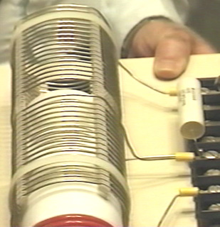 The "L2" coil has two separate sections, each of seventeen turns. One point to note is the turns are spaced apart using slotted strips to support the wires and maintain an accurate spacing between adjacent turns. It must be remembered that spacing coil turns apart like this alters the characteristics of the coil, increasing it's "capacitance" factor substantially. Every coil has resistance, inductance and capacitance, but the form of the coil construction has a major effect on the ratio of these three characteristics. The coil assembly is held in position on the base board by two off-white plastic cable ties. The nearer half of the coil is effectively connected across the further half as shown in the circuit diagram above. One point which Don stresses, is that the length of the wire in the "L1" coil and the length of wire in the "L2" coil, must be an exact even division or multiple of each other (in this case, the "L2" wire length in each half of the "L2" coil is exactly four times as long as the "L1" coil wire length). This is likely to cause the "L1" coil to have part of a turn, due to the different coil diameters. For example, if the length of the "L2" coil wire is 160 inches and "L1" is to be one quarter of that length, namely, 40 inches. Then, if the "L1" coil has an effective diameter of 2.25 inches, (allowing for the thickness of the wire when wound on a 2-inch diameter former), then the "L1" coil would have 5.65 (or 5 and 2/3) turns which causes the finishing turn of "L2" to be 240 degrees further around the coil former than the start of the first turn - that is, five full turns plus two thirds of the sixth turn. The L1 / L2 coil arrangement is a Tesla Coil. The positioning of the "L1" coil along the length of the "L2" coil, adjusts the voltage to current ratio produced by the coil. When the "L1" coil is near the middle of the "L2" coil, then the amplified voltage and amplified current are roughly the same. The exact wire ratio of these two coils gives them an almost automatic tuning with each other, and the exact resonance between them can be achieved by the positioning of the "L1" coil along the length of the "L2" coil. While this is a perfectly good way of adjusting the circuit, in the build shown in the photograph, Don has opted to get the exact tuning by connecting a capacitor across "L1" as marked as "C" in the circuit diagram. Don found that the appropriate capacitor value was around the 0.1 microfarad (100 nF) mark. It must be remembered that the voltage across "L1" is very high, so if a capacitor is used in that position it will need a voltage rating of at least 9,000 volts. Don remarks that the actual capacitors seen in the photograph of this prototype are rated at fifteen thousand volts, and were custom made for him using a "self-healing" style of construction. As has already been remarked, this capacitor is an optional component. Don also opted to connect a small capacitor across the "L2" coil, also for fine-tuning of the circuit, and that component is optional and so is not shown on the circuit diagram. As the two halves of the "L2" coil are effectively connected across each other, it is only necessary to have one fine-tuning capacitor. However, Don stresses that the "height" length of the coil (when standing vertically) controls the voltage produced while the coil "width" (the diameter of the turns) controls the current produced. 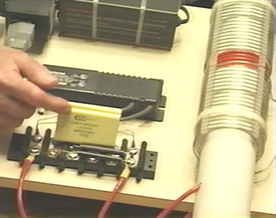 The exact wire length ratio of the turns in the "L1" and "L2" coils gives them an almost automatic synchronous tuning with each other, and the exact resonance between them can be achieved by the positioning of the "L1" coil along the length of the "L2" coil. While this is a perfectly good way of adjusting the circuit, in the 1994 build shown in the photograph, Don has opted to get the exact tuning by connecting a capacitor across "L1" as marked as "C" in the circuit diagram. Don found that the appropriate capacitor value for his particular coil build, was about 0.1 microfarad (100 nF) and so he connected two 47 nF high-voltage capacitors in parallel to get the value which he wanted. It must be remembered that the voltage across "L1" is very high, so a capacitor used in that position needs a voltage rating of at least 9,000 volts. Don remarks that the actual capacitors seen in the photograph of this prototype are rated at fifteen thousand volts, and were custom made for him using a "self-healing" style of construction. Don has also connected a small capacitor across the "L2" coil, and that optional component is marked as "C2" in the circuit diagram and the value used by Don happened to be a single 47nF, high-voltage capacitor. As the two halves of the "L2" coil are effectively connected across each other, it is only necessary to have one capacitor for "L2": 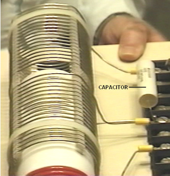 There are various ways of dealing with the output from the "L2" coil in order to get large amounts of conventional electrical power out of the device. The method shown here uses the four very large capacitors seen in the photograph. These have an 8,000 or 9,000 volt rating and a large capacity and they are used to store the circuit power as DC prior to use in the load equipment. This is achieved by feeding the capacitor bank through a diode which is rated for both high voltage and high current, as Don states that the device produces 8,000 volts at 20 amps, in which case, this rectifying diode has to be able to handle that level of power, both at start-up when the capacitor bank is fully discharged and "L2" is producing 8,000 volts, and when the full load of 20 amps is being drawn. This capacitor bank is fed through a diode which is rated for both high voltage and high current, as Don states that the device produces 8,000 volts at 20 amps, in which case, this rectifying diode has to be able to handle that level of power, both at start-up when the capacitor bank is fully discharged and "L2" is producing 8,000 volts, and when the full load of 20 amps is being drawn. The actual diodes used by Don happen to be rated at 25 KV but that is a far greater rating than is actually needed. In passing, it might be remarked that the average home user will not have an electrical requirement of anything remotely like as large as this, seeing that 10 kW is more than most people use on a continuous basis, while 8 KV at 20 A is a power of 160 kilowatts. As the neon-tube driver circuit can put out 9,000 volts and since the L1 / L2 coil system is a step-up transformer, if the voltage fed to the capacitor bank is to be kept down to 8,000 volts, then the Variac adjustment must be used to reduce the voltage fed to the neon-tube driver circuit, in order to lower the voltage fed to the L1 / L2 coil pair, typically, to 3,000 volts. A very astute and knowledgeable member of the EVGRAY Yahoo EVGRAY forum whose ID is "silverhealtheu" has recently pointed out that Don Smith says quite freely that he does not disclose all of the details of his designs, and it is his opinion that a major item which has not been disclosed is that the diodes in the circuit diagrams shown here are the wrong way round and that Don operates his voltages in reverse to the conventional way. In fact, the circuit diagram should be: He comments: "the diodes leaving the Neon-tube Driver may need to be reversed as we want to collect the negative polarity. The spark gap will then operate on ambient inversion and the spark will look and sound totally different with a much faster crack and producing very little heat and even becoming covered in frost is possible. The Variac should be raised up just enough to get a spark going then backed off slightly. Any higher voltage is liable to make the Neon-tube Driver think that it has a short-circuit condition, and the new electronic designs will then shut down automatically and fail to operate at all if this method is not followed. When running, C, L1 and L2 operate somewhere up in the Radio Frequency band because the Neon-tube Driver only acts as a tank-circuit exciter. The large collection capacitor C3, should fill inverted to earth polarity as shown above. The load will then be pulling electrons from the earth as the cap is REFILLED back to ZERO rather than the joules in the capacitor being depleted. Also remember that the Back-EMF systems of John Bedini and others, create a small positive pulse but they collect a super large NEGATIVE polarity spike which shoots off the bottom of an oscilloscope display. This is what we want, plenty of this stored in capacitors, and then let the ambient background energy supply the current when it makes the correction." This is a very important point and it may well make a really major difference to the performance of a device of this nature.  One reader has drawn attention to the fact that Don's main document indicates that there should be a resistor "R" across the L1 coil as well as the capacitor "C" and he suggests that the circuit should actually be as shown above, considering what Don said earlier about his "suitcase" design. Another reader points out that the wire in the output choke shown in the photograph below appears to be wound with wire that is far too small diameter to carry the currents mentioned by Don. It seems likely that a choke is not needed in that position except to suppress possible radio frequency transmissions from the circuit, but a more powerful choke can easily be wound using larger diameter wire. When the circuit is running, the storage capacitor bank behaves like an 8,000 volt battery which never runs down and which can supply 20 amps of current for as long as you want. The circuitry for producing a 220 volt 50 Hz AC output or a 110 volt 60 Hz AC output from the storage capacitors is just standard electronics. In passing, one option for charging the battery is to use the magnetic field caused by drawing mains-frequency current pulses through the output "choke" coil, shown here: 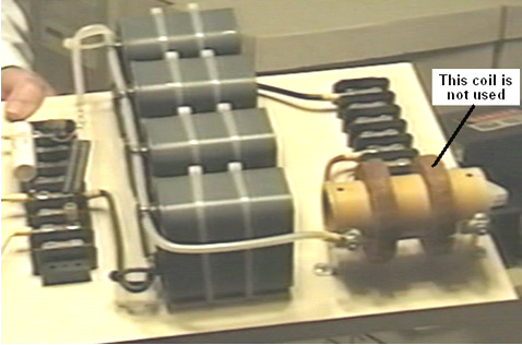 The output current flows through the left hand winding on the brown cylindrical former, and when the photograph was taken, the right-hand winding was no longer in use. Previously, it had been used to provide charging power to the battery by rectifying the electrical power in the coil, caused by the fluctuating magnetic field caused by the pulsing current flowing through the left hand winding, as shown here:  The DC output produced by the four diodes was then used to charge the driving battery, and the power level produced is substantially greater than the minor current drain from the battery. Consequently, it is a sensible precaution to pass this current to the battery via a circuit which prevents the battery voltage rising higher than it should. A simple voltage level sensor can be used to switch off the charging when the battery has reached its optimum level. Other batteries can also be charged if that is wanted. Simple circuitry of the type shown in chapter 12 can be used for controlling and limiting the charging process. The components on Don's board are laid out like this:  Don draws attention to the fact that the cables used to connect the output of "L2" to the output of the board, connecting the storage capacitors on the way, are very high-voltage rated cables with special multiple coverings to ensure that the cables will remain sound over an indefinite period. It should be remarked at this point, that the outer 3" diameter coil used by Don, is not wound on a former, but in order to get higher performance at high frequencies, the turns are supported with four separate strips physically attached to the turns - the technique described later in this document as being an excellent way for home construction of such coils. Please bear in mind that the voltages here and their associated power levels are literally lethal and perfectly capable of killing anyone who handles the device carelessly when it is powered up. When a replication of this device is ready for routine use, it must be encased so that none of the high-voltage connections can be touched by anyone. This is not a suggestion, but it is a mandatory requirement, despite the fact that the components shown in the photographs are laid out in what would be a most dangerous fashion were the circuit to be powered up as it stands. Under no circumstances, construct and test this circuit unless you are already experienced in the use of high-voltage circuits or can be supervised by somebody who is experienced in this field. This is a "one hand in the pocket at all times" type of circuit and it needs to be treated with great care and respect at all times, so be sensible. The remainder of the circuit is not mounted on the board, possibly because there are various ways in which the required end result can be achieved. The one suggested here is perhaps the most simple solution:  The voltage has to be dropped, so an iron-cored mains-frequency step-down transformer is used to do this. To get the frequency to the standard mains frequency for the country in which the device is to be used, an oscillator is used to generate that particular mains frequency. The oscillator output is used to drive a suitable high-voltage semiconductor device, be it an FET transistor, an IGBT device, or whatever. This device has to switch the working current at 8,000 volts, though admittedly, that will be a current which will be at least thirty six times lower than the final output current, due to the higher voltage on the primary winding of the transformer. The available power will be limited by the current handling capabilities of this output transformer which needs to be very large and expensive. As the circuit is capable of picking up additional magnetic pulses, such as those generated by other equipment, nearby lightning strikes, etc. an electronic component called a "varistor" marked "V" in the diagram, is connected across the load. This device acts as a voltage spike suppressor as it short circuits any voltage above its design voltage, protecting the load from power surges. Don also explains an even more simple version of the circuit as shown here:  This simplified circuit avoids the need for expensive capacitors and the constraints of their voltage ratings, and the need for electronic control of the output frequency. The wire length in the turns of coil "L2" still needs to be exactly four times the wire length of the turns in coil "L1", but there is only one component which needs to be introduced, and that is the resistor "R" placed across the primary winding of the step-down isolation transformer. This transformer is a laminated iron-core type, suitable for the low mains frequency, but the output from "L2" is at much higher frequency. It is possible to pull the frequency down to suit the step-down transformer by connecting the correct value of resistor "R" across the output transformer (or a coil and resistor, or a coil and a capacitor). The value of resistor needed can be predicted from the American Radio Relay League graph (shown as Fig.44 in Don's pdf document. The sixth edition of the Howard Sams book "Handbook of Electronics Tables and Formulas" (ISBN-10: 0672224690 or ISBN-13: 978-0672224690) has a table which goes down to 1 kHz and so does not need to be extended to reach the frequencies used here. The correct resistor value could also be found by experimentation. You will notice that an earthed dual spark gap has been placed across "L2" in order to make sure that the voltage levels always stay within the design range. Don also explains an even more simple version which does not need a Variac, high voltage capacitors or high voltage diodes. Here, a DC output is accepted which means that high-frequency step-down transformer operation can be used. This calls for an air-core transformer which you would wind yourself from heavy duty wire. Mains loads would then be powered by using a standard off-the-shelf inverter. In this version, it is of course, necessary to make the "L1" turns wire length exactly one quarter of the "L2" turns wire length in order to make the two coils resonate together. The operating frequency of each of these coils is imposed on them by the output frequency of the neon-tube driver circuit. That frequency is maintained throughout the entire circuit until it is rectified by the four diodes feeding the low-voltage storage capacitor. The target output voltage will be either just over 12 volts or just over 24 volts, depending on the voltage rating of the inverter which is to be driven by the system. The circuit diagram is:  As many people will find the nomograph chart in Don's pdf document very difficult to understand and use, here is an easier version:  The objective here is to determine the "reactance" or 'AC resistance' in ohms and the way to do that is as follows: Suppose that your neon-tube driver is running at 30 kHz and you are using a capacitor of 100 nF (which is the same as 0.1 microfarad) and you want to know what is the AC resistance of your capacitor is at that frequency. Also, what coil inductance would have that same AC resistance. Then the procedure for finding that out is as follows:  Draw a straight line from your 30 kHz frequency (purple line) through your 100 nanofarad capacitor value and carry the line on as far as the (blue) inductance line as shown above. You can now read the reactance ("AC resistance") off the red line, which looks like 51 ohms to me. This means that when the circuit is running at a frequency of 30 kHz, then the current flow through your 100 nF capacitor will be the same as through a 51 ohm resistor. Reading off the blue "Inductance" line that same current flow at that frequency would occur with a coil which has an inductance of 0.28 millihenries. I have been passed a copy of Don’s circuit diagram for this device, and it is shown here:  The 4000V 30mA transformer shown in this circuit diagram, may use a ferrite-cored transformer from a neon-tube driver module which steps up the voltage but it does not raise the frequency as that is clearly marked at 120 Hz pulsed DC. You will notice that this circuit diagram is drawn with Plus shown below Minus (which is most unusual). Please note that when an earth connection is mentioned in connection with Don Smith's devices, we are talking about an actual wire connection to a metal object physically buried in the ground, whether it is a long copper rod driven into the ground, or an old car radiator buried in a hole like Tariel Kapanadze used, or a buried metal plate. When Thomas Henry Moray performed his requested demonstration deep in the countryside at a location chosen by the sceptics, the light bulbs which formed his demonstration electrical load, glowed more brightly with each hammer stroke as a length of gas pipe was hammered into the ground to form his earth connection. Don also explains an even more simple version of his main device. This version does not need a Variac (variable voltage transformer) or high voltage capacitors. Here, a DC output is accepted which means that high-frequency step-down transformer operation can be used. This calls on the output side, for an air-core (or ferrite rod core) transformer which you would wind yourself from heavy duty wire. Mains loads would then be powered by using a standard off-the-shelf inverter. In this version, it is of course, very helpful to make the "L1" turns wire length exactly one quarter of the "L2" turns wire length in order to make the two coils automatically resonate together. The operating frequency of each of these coils is imposed on them by the output frequency of the neon-tube driver circuit. That frequency is maintained throughout the entire circuit until it is rectified by the four diodes feeding the low-voltage storage capacitor. The target output voltage will be either just over 12 volts or just over 24 volts, depending on the voltage rating of the inverter which is to be driven by the system. As the circuit is capable of picking up additional magnetic pulses, such as those generated by other equipment, nearby lightning strikes, etc. an electronic component called a "varistor" marked "V" in the diagram, is connected across the load. This device acts as a voltage spike suppressor as it short-circuits any voltage above its design voltage, protecting the load from power surges. A Gas-Discharge Tube is an effective alternative to a varistor. This circuit is effectively two Tesla Coils back-to-back and the circuit diagram might be:  It is by no means certain that in this circuit, the red and blue windings are wound in opposing directions. The spark gap (or gas-discharge tube) in series with the primary of the first transformer alters the operation in a somewhat unpredictable way as it causes the primary to oscillate at a frequency determined by it’s inductance and it’s self-capacitance, and that may result in megahertz frequencies. The secondary winding(s) of that transformer must resonate with the primary and in this circuit which has no frequency-compensating capacitors, that resonance is being produced by the exact wire length in the turns of the secondary. This looks like a simple circuit, but it is anything but that. The excess energy is produced by the raised frequency, the raised voltage, and the very sharp pulsing produced by the spark. That part is straightforward. The remainder of the circuit is likely to be very difficult to get resonating as it needs to be in order to deliver that excess energy to the output inverter. When considering the “length” of wire in a resonant coil, it is necessary to pay attention to the standing wave created under those conditions. The wave is caused by reflection of the signal when it reaches the end of the wire OR when there is a sudden change in the diameter of the wire as that changes the signal reflection ability at that point in the connection. You should pay attention to Richard Quick’s very clear description of this in the section of his patent which is included later on in this chapter. Also, remember what Don Smith said about locating the peaks of the standing wave by using a hand-held neon lamp. One very significant thing which Don pointed out is that the mains electricity available through the wall socket in my home, does not come along the wires from the generating station. Instead, the power station influences a local ‘sub-station’ and the electrons which flow through my equipment actually come from my local environment because of the influence of my local sub-station. Therefore, if I can create a similar influence in my home, then I no longer need that sub-station and can have as much electrical energy as I want, without having to pay somebody else to provide that influence for me. A Practical Implementation of one of Don Smith’s Designs The objective here, is to determine how to construct a self-powered, free-energy electrical generator which has no moving parts, is not too expensive to build, uses readily available parts and which has an output of some kilowatts. However, under no circumstances should this document be considered to be an encouragement for you, or anyone else to actually build one of these devices. This document is presented solely for information and educational purposes, and as high voltages are involved, it should be considered to be a dangerous device unsuited to being built by inexperienced amateurs. The following section is just my opinions and so should not be taken as tried and tested, working technology, but instead, just the opinion of an inexperienced writer. However, questions from several different readers indicate that a short, reasonably specific description of the steps needed to attempt a replication of a Don Smith device would be helpful. Again, this document must not be considered to be a recommendation that you actually build one of these high-voltage, potentially dangerous devices. This is just information intended to help you understand what I believe is involved in this process. In broad outline, the following steps are used in the most simple version of the arrangement: 1. The very low frequency and voltage of the local mains supply is discarded in favour of an electrical supply which operates at more than 20,000 Hz (cycles per second) and has a voltage of anything from 350 volts to 10,000 volts. The higher voltages can give greater overall output power, but they involve greater effort in getting the voltage back down again to the level of the local mains voltage in order for standard mains equipment to be used. 2. This high-frequency high voltage is used to create a series of very rapid sparks using a spark gap which is connected to a ground connection. Properly done, the spark frequency is so high that there is no audible sound caused by the sparks. Each spark causes a flow of energy from the local environment into the circuit. This energy is not standard electricity which makes things hot when current flows through them, but instead this energy flow causes things to become cold when the power flows through them, and so it is often called “cold” electricity. It is tricky to use this energy unless all you want to do is light up a series of light bulbs (which incidentally, give out a different quality of light when powered with this energy). Surprisingly, the circuit now contains substantially more power than the amount of power needed to produce the sparks. This is because additional energy flows in from the ground as well as from the local environment. If you have conventional training and have been fed the myth of “closed systems”, then this will seem impossible to you. So, let me ask you the question: if, as can be shown, all of the electricity flowing into the primary winding of a transformer, flows back out of that winding, then where does the massive, continuous flow of electricity coming from the secondary winding come from? None of it comes from the primary circuit and yet millions of electrons flow out of the secondary in a continuous stream which can be supplied indefinitely. So, where do these electrons come from? The answer is ‘from the surrounding local environment which is seething with excess energy’ but your textbooks won’t like that fact as they believe that the transformer circuit is a ‘closed system’ – something which probably can’t be found anywhere in this universe. 3. This high-voltage, high-frequency, high-power energy needs to be converted to the same sort of hot electricity which comes out of a mains wall socket at the local voltage and frequency. This is where skill and understanding come into play. The first step is to lower the voltage and increase the available current with a step-down resonant transformer. This sounds highly technical and complicated, and looking at Don Smith’s expensive Barker & Williamson coil, makes the whole operation appear to be one for rich experimenters only. This is not the case and a working solution can be cheap and easy. It is generally not convenient to get the very high voltage all the way down to convenient levels in a single step, and so, one or more of those resonant transformers can be used to reach the target voltage level. Each step down transformer boosts the available current higher and higher. 4. When a satisfactory voltage has been reached, we need to deal with the very high frequency. The easiest way to deal with it is to use high-speed diodes to convert it to pulsing DC and feed that into a capacitor to create what is essentially, an everlasting battery. Feeding this energy into a capacitor converts it into conventional “hot” electricity and a standard off-the-shelf inverter can be used to give the exact voltage and frequency of the local mains supply. In most of the world, that is 220 volts at 50 cycles per second. In America it is 110 volts at 60 cycles per second. Low-cost inverters generally run on either 12 volts or 24 volts with the more common 12 volt units being cheaper. So, let’s take a look at each of these step in more detail and see if we can understand what is involved and what our options are: 1. We want to produce a high-voltage, high-frequency, low-current power source. Don Smith shows a Neon-Sign Transformer module. His module produced a voltage which was higher than was convenient and so he used a variable AC transformer or “Variac” as it is commonly known, to lower the input voltage and so, lower the output voltage. There is actually no need for a Variac as we can handle the higher voltage or alternatively, use a more suitable Neon-Sign Transformer module. However, we have a problem with using that technique. In the years since Don bought his module, they have been redesigned to include circuitry which disables the module if any current flows out of it directly to earth, and as that is exactly what we would want to use it for, so most, if not all of the currently available neon-sign transformer modules are not suitable for our needs. However, I’m told that if the module has an earth wire and that earth wire is left unconnected, that it disables the earth-leakage circuitry, allowing the unit to be used in a Don Smith circuit. Personally, I would not recommend that if the module is enclosed in a metal housing. A much cheaper alternative is shown here where a small plasma globe circuit is used to generate a high-frequency spark. It seems highly likely that one of those modules would suit our needs:  An alternative method is to build your own power supply from scratch. Doing that is not particularly difficult and if you do not understand any electronics, then perhaps, reading the beginner’s electronics tutorial here will fill you in on all of the basics needed for understanding (and probably designing your own) circuits of this type. Here is a variable frequency design for home-construction:  One advantage of this circuit is that the output transformer is driven at the frequency set by the 555 timer and that frequency is not affected by the number of turns in the primary winding, nor it’s inductance, wire diameter, or anything else to do with the coil. While this circuit shows the rather expensive IRF9130 transistor, I expect that other P-channel FETs would work satisfactorily in this circuit. The IRF9130 transistor looks like this:  The circuit has a power supply diode and capacitor, ready to receive energy from the output at some later date if that is possible and desired. The 555 circuit is standard, giving a 50% Mark/Space ratio. The 10 nF capacitor is there to maintain the stability of the 555 and the timing section consists of two variable resistors, one fixed resistor and the 1 nF capacitor. This resistor arrangement gives a variable resistance of anything from 100 ohms to 51.8K and that allows a substantial frequency range. The 47K (Linear) variable resistor controls the main tuning and the 4.7K (Linear) variable resistor gives a more easily adjustable frequency for exact tuning. The 100 ohm resistor is there in case both of the variable resistors are set to zero resistance. The output is fed through a 470 ohm resistor to the gate of a very powerful P-channel FET transistor which drives the primary winding of the output transformer. The output transformer can be wound on an insulating spool covering a ferrite rod, giving both good coupling between the windings, and high-frequency operation as well. The turns ratio is set to just 30:1 due to the high number of primary winding turns. With a 12-volt supply, this will give a 360-volt output waveform, and by reducing the primary turns progressively, allows the output voltage to be increased in controlled steps. With 10 turns in the primary, the output voltage should be 3,600 volts and with just 5 turns 7,200 volts. The higher the voltage used, the greater the amount of work needed later on to get the voltage back down to the output level which we want. Looking at the wire specification table, indicates that quite a small wire diameter could be used for the oscillator output transformer’s secondary winding. While this is perfectly true, it is not the whole story. Neon Tube Drivers are very small and the wire in their output windings is very small diameter indeed. Those driver modules are very prone to failure. If the insulation on any one turn of the winding fails and one turn becomes a short-circuit, then that stops the winding from oscillating, and a replacement is needed. As there are no particular size constraints for this project, it might be a good idea to use enamelled copper wire of 0.45 mm or larger in an attempt to avoid this insulation failure hazard. No part of the transformer coil spool should be metal and it would not be any harm to cover each layer of secondary winding with a layer of electrical tape to provide additional insulation between the coil turns in one layer and the turns in the layer on top of it. A plug-in board layout might be:  Please remember that you can’t just stick your average voltmeter across a 4 kV capacitor (unless you really do want to buy another meter) as they only measure up to about a thousand volts DC. So, if you are using high voltage, then you need to use a resistor-divider pair and measure the voltage on the lower resistor. But what resistor values should you use? If you put a 10 Megohm resistor across your 4 kV charged capacitor, the current flowing through the resistor would be 0.4 milliamps. Sounds tiny, doesn’t it? But that 0.4 mA is 1.6 watts which is a good deal more than the wattage which your resistor can handle. Even using this arrangement:  the current will be 0.08 mA and the wattage per resistor will be 64 mW. The meter reading will be about 20% of the capacitor voltage which will give a voltmeter reading of 800 volts. The input resistance of the meter needs to be checked and possibly, allowed for as the resistance in this circuit is so high (see chapter 12). When making a measurement of this type, the capacitor is discharged, the resistor chain and meter attached, and then, and only then, is the circuit powered up, the reading taken, the input power disconnected, the capacitor discharged, and the resistors disconnected. High-voltage circuits are highly dangerous, especially so, where a capacitor is involved. The recommendation to wear thick rubber gloves for this kind of work, is not intended to be humorous. Circuits of this type are liable to generate unexpected high-voltage spikes, and so, it might be a good idea to connect a varistor across the meter to protect it from those spikes. The varistor need to be set to the voltage which you intend to measure and as varistors may not be available above a 300V threshold, two or more may need to be connected in series where just one is shown in the diagram above. The varistor should not have a higher voltage rating than your meter. 2. We now need to use this high voltage to create a strategically positioned spark to a ground connection. When making an earth connection, it is sometimes suggested that connecting to water pipes or radiators is a good idea as they have long lengths of metal piping running under the ground and making excellent contact with it. However, it has become very common for metal piping to be replaced with cheaper plastic piping and so any proposed pipe connection needs a check to ensure that that there is metal piping which runs all the way into the ground.  The spark gaps shown can be commercial high-voltage gas discharge tubes, adjustable home-made spark gaps with stainless steel tips about 1 mm apart, car spark plugs, or standard neon bulbs, although these run rather hot in this application. A 15 mm x 6 mm size neon bulb operates with only 90 or 100 volts across it, it would take a considerable number of them connected in series to create a high voltage spark gap, but it is probably a misconception that the spark gap itself needs a high voltage. Later on in this chapter, there is an example of a very successful system where just one neon bulb is used for the spark gap and an oscillating magnetic field more than a meter wide is created when driven by just an old 2,500 volt neon-sign transformer module. If using a neon bulb for the spark gap, then an experienced developer recommends that a 22K resistor is used in series with the neon in order to extend it’s working life very considerably. This circuit is one way to connect the spark gap and ground connection:  This is an adaption of a circuit arrangement used by the forum member “SLOW-‘N-EASY” on the Don Smith topic in the energeticforum. Here, he is using a ‘LowGlow’ neon transformer intended for use on a bicycle. The diodes are there to protect the high-voltage power supply from any unexpected voltage spikes created later on in the circuit. The spark gap is connected between the primary winding of a step-up transformer and the earth connection. No capacitor is used. Seeing this circuit, we immediately think of Don Smith’s large and expensive coils, but this experimenter does not use anything like that. Instead, he winds his transformer on a simple plastic former like this:  And to make matters ‘worse’ the primary winding wire is just 9 inches (228.6 mm) long and the secondary just 36 inches (914.4 mm) long, the primary being wound directly on top of the secondary. Not exactly a large or expensive construction and yet one which appears to perform adequately in actual tests. This is a very compact form of construction, but there is no necessity to use exactly the same former for coils, nor is there anything magic about the nine-inch length of the L1 coil, as it could easily be any convenient length, say two feet or 0.5 metres, or whatever. The important thing is to make the L2 wire length exactly four times that length, cutting the lengths accurately. It is common practice to match the weight of copper in each coil and so the shorter wire is usually twice the diameter of the longer wire. The circuit above, produces a cold electricity output of high voltage and high frequency. The voltage will not be the same as the neon transformer voltage, nor is the frequency the same either. The two coils resonate at their own natural frequency, unaltered by any capacitors. 3. The next step is to get the high voltage down to a more convenient level, perhaps, like this:  Here, an identical transformer, wound in exactly the same way, is used in reverse, to start the voltage lowering sequence. The wire length ratio is maintained to keep the transformer windings resonant with each other. Supposing we were to wind the L2 coil of this second transformer in a single straight winding and instead of winding just one L1 winding on top of it, two or more L1 identical windings were placed on top of it – what would happen?:  Now for a comment which will seem heretical to people steeped in the present day (inadequate) level of technology. The power flowing in these transformers is cold electricity which operates in an entirely different way to hot electricity. The coupling between these coils would be inductive if they were carrying hot electricity and in that case, any additional power take-off from additional L1 coils would have to be ‘paid’ for by additional current draw through the L2 coil. However, with the cold electricity which these coils are actually carrying, the coupling between the coils is magnetic and not inductive and that results in no increase in L2 current, no matter how many L1 coil take-offs there are. Any additional L1 coils will be powered for free. However, the position of the coils relative to each other has an effect on the tuning, so the L1 coil should be in the middle of the L2 coil, which means that any additional L1 coils are going to be slightly off the optimum tuning point. 4. Anyway, following through on just one L1 coil, there is likely to be at least one further step-down transformer needed and eventually, we need conversion to hot electricity:  Probably the easiest conversion is by feeding the energy into a capacitor and making it standard DC. The frequency is still very high, so high-speed diodes (such as the 75-nanosecond UF54008) are needed here although the voltage level is now low enough to be no problem. The DC output can be used to power an inverter so that standard mains equipment can be used. It is not necessary to use just one (expensive) large-capacity inverter to power all possible loads as it is cheaper to have several smaller inverters, each powering it’s own set of equipment. Most equipment will run satisfactorily on square-wave inverters and that includes a mains unit for powering the input oscillator circuit. PVC pipe is not a great material when using high-frequency high-voltage signals, and grey PVC pipe is a particularly poor coil former material. The much more expensive acrylic pipe is excellent, but if using PVC, then performance will be better if the PVC pipe is coated with an insulating lacquer (or table tennis balls dissolved in acetone as show on YouTube). However, there are some other factors which have not been mentioned. For example, if the L1 coil is wound directly on top of the L2 coil, it will have roughly the same diameter and so, the wire being four times longer, will have roughly four times as many turns, giving a step-up or step-down ratio of around 4:1. If, on the other hand, the coil diameters were different, the ratio would be different as the wire lengths are fixed relative to each other. If the L2 coil were half the diameter of the L1 coil, then the turns ratio would be about 8:1 and at one third diameter, 12:1 and at a quarter diameter 16:1 which means that a much greater effect could be had from the same wire length by reducing the L2 coil diameter. However, the magnetic effect produced by a coil is linked to the cross-sectional area of the coil and so a small diameter is not necessarily at great advantage. Also, the length of the L1 coil wire and number of turns in it, affect the DC resistance, and more importantly, the AC impedance which affects the amount of power needed to pulse the coil. It is also thought that having the same weight of copper in each winding gives an improved performance, but what is not often mentioned is the opinion that the greater the weight of copper, the greater the effect. You will recall that Joseph Newman (chapter 11) uses large amounts of copper wire to produce remarkable effects. So, while 9 inches and 36 inches of wire will work for L1 and L2, there may well be improved performance from longer lengths of wire and/or thicker wires. We should also not forget that Don Smith pointed out that voltage and current act (out of phase and) in opposite directions along the L2 coil, moving away from the L1 coil:  It has been suggested that a greater and more effective power output can be obtained by splitting the L2 coil underneath the L1 coil position, winding the second part of L2 in the opposite direction and grounding the junction of the two L2 windings. Don doesn’t consider it necessary to reverse the direction of winding. The result is an L2 winding which is twice as long as before and arranged like this:  Here, the additional high-voltage diodes allow the two out of phase windings to be connected across each other. You will notice that this arrangement calls for two separate earth connections, both of which need to be high-quality connections, something like a pipe or rod driven deeply into moist soil or alternatively, a metal plate or similar metal object of substantial surface area, buried deep in moist earth, and a thick copper wire or copper braid used to make the connection. These earthing points need to be fairly far apart, say, ten metres. A single earth connection can’t be used as that would effectively short-circuit across the L1/L2 transformer which you really do not want to do. With this arrangement, the outline circuit becomes:  The thick earth wiring is helpful because in order to avoid the earth wire being included in the resonant wire length, you need a sudden change in wire cross-section:  These are just some ideas which might be considered by some experienced developer who may be thinking of investigating Don Smith style circuitry. To give you some idea of the capacity of some commercially available wires when carrying hot electricity, this table may help:  It is recommended that the wire have a current carrying capacity of 20% more than the expected actual load, so that it does not get very hot when in use. The wire diameters do not include the insulation, although for solid enamelled copper wire, that can be ignored. There is a most impressive video and circuit shown here where a very simple arrangement produces an immediately successful performance for the front end of Don’s circuitry. The circuit appears to be:  Here, a simple Neon Sign Transformer module which has no earth connection, is used to produce a 2.5 kV voltage with a frequency of 25 kHz and a maximum output current capacity of 12 mA. There is no difficulty in constructing the equivalent to that power supply unit. The two outputs from the module are converted to DC by a chain of four 1N4007 diodes in series in each of the two outputs (each chain being inside a plastic tube for insulation). This output is fed through an optional 22K resistor via a neon lamp to a microwave oven capacitor which happens to be 874 nF with a voltage rating of 2,100 volts. You might feel that the voltage rating of the capacitor is too low for the output voltage of the neon sign module, but the neon has a striking voltage of just 90 volts and so the capacitor is not going to reach the output voltage of the power supply. The resistors are solely to extend the life of the neons as the gas inside the tube gets a considerable jolt in the first nanosecond after switch-on. It is unlikely that omitting those resistors would have any significant effect, but then, including them is a trivial matter. The second neon feeds the primary of the resonant transformer which is only shown in notional outline in the diagram above as the developer suggests that the primary acts as a transmitter and that any number of receiving coils can be used as individual secondaries by being tuned to the exact frequency of that resonating primary.  In the video showing this arrangement, the developer demonstrates the fluctuating, high-frequency field which extends for some four feet (1.2 m) around the coil. He also remarks that the single neons in his arrangement could each be replaced with two neons in series. In test which I ran, I found that I needed two neons in series ahead of the capacitor in order to get continuous lighting of the output neon. Also, one of the diodes needed to be reversed so that one faced towards the input and one away from it. It did not matter which diode was reversed as both configurations worked. Again, please note that this presentation is for information purposes only and it is NOT a recommendation that you should actually build one of these devices. Let me stress again that this is a high-voltage device made even more dangerous by the inclusion of a capacitor, and it is quite capable of killing you, so, don’t build one. The developer suggests that it is an implementation of the “transmitter” section of Don’s Transmitter/multiple-receivers design shown below. However, before looking at that design, there is one question which causes a good deal of discussion on the forums, namely, if the centre-tap of the L2 secondary coil is connected to ground, then should that earth-connection wire length be considered to be part of the quarter length of the L1 coil? To examine this possibility in depth, the following quote from Richard Quick’s very clear explanation of resonance in his US patent 7,973,296 of 5th July 2011 is very helpful. However, the simple answer is that for there to be exact resonance between two lengths of wire (whether or not part, or all of those lengths of wire happen to be wound into a coil), then one length needs to be exactly four times as long as the other, and ideally, half the diameter as well. At both ends of both lengths of wire, there needs to be a sudden change in wire diameter and Richard explains why this is. But, leaving that detailed explanation for now, we can use that knowledge to explain the above simplified system in more detail. Here is the circuit again:  One very important point to note is that no earth connection is required and in spite of that, the performance shown on video is very impressive. While an earth connection can feed substantial power into the circuit, not needing one for the front end is an enormous advantage and potentially, opens the way for a truly portable device. Another very important point is the utter simplicity of the arrangement where only cheap, readily available components are used (and not many of those are needed). The resistors for extending the life of the neon bulbs are not shown, but they can be included if desired and the circuit operation is not altered significantly by having them there. If a higher spark voltage is wanted, then two or more neon bulbs can be used in series where these circuit diagrams show just one. A point to note is that the lower diode is shown reversed when compared to the previous diagram. This is because the power supply shown is any generic power supply which drives a simple output coil which does not have a centre tap. The neon supply of the earlier diagram appears to have two separate outputs which will, presumably, be out of phase with each other as that is common practice for neon-sign driver modules. If you wish, the two diodes shown here could be replaced by a diode bridge of four high-voltage, high-speed diodes. The wire lengths of L1 and L2 are measured very accurately from where the wire diameter changes suddenly, as indicated by the red dashed lines. The L2 wire length is exactly four times as long as the L1 wire length and the L2 wire diameter is half of the L1 wire diameter. How long is the L1 wire? Well, how long would you like it to be? It can be whatever length you want and the radius of the L1 coil can be whatever you want it to be. The theory experts will say that the L1 coil should resonate at the frequency of the power feeding it. Well, good for them, I say, so please tell me what frequency that is. It is not going to be the frequency of the power supply as that will be changed by at least one of the neon bulbs. So, what frequency will the neon bulb produce? Not even the manufacturer could tell you that as there is quite a variation between individual bulbs which are supposedly identical. Actually, it doesn’t matter at all, because the L1 coil (and the L2 coil if you measure them accurately) has a resonant frequency all of its own and it will vibrate at that frequency no matter what the frequency feeding it happens to be. A coil resonates in very much the same way that a bell rings when it is struck. It doesn’t matter how hard you strike the bell or how rapidly you strike it – the bell will ring at it’s own natural frequency. So the L1 coil will resonate at it’s own natural frequency no matter what rate the voltage spikes striking it arrive, and as the L2 coil has been carefully constructed to have exactly that same frequency, it will resonate in synchronisation with the L1 coil. This means that the length of the wire for the L1 coil is the choice of the builder, but once that length is chosen it determines the length of the wire for the L2 coil as that is exactly four times as long, unless the builder decides to use an arrangement which has L2 wound in both the Clockwise and counter-clockwise directions, in which case, each half of the L2 coil will be four times the length of the wire in the L1 coil, like this:  Mind you, there is one other factor to be considered when deciding what the most convenient wire length for L1 might be, and that is the number of turns in the L1 coil. The larger the ratio between the turns in L1 and the turns in L2, the higher the voltage boost produced by the L1/L2 transformer, and remember that the length of L2 is fixed relative to the length of L1. So, a possible circuit style might be:  There are some important points to remember. One is that there must be a sudden change of wire diameter at both ends of each L1 coil and at the ends of each L2 coil. If there isn’t, then the connecting wire length will form part of the coil and if there is some change in diameter but not very much, then it is anybody’s guess what the resonant wire length for that coil will be. There can be as many step-down isolation air-core L1/L2 transformers as desired and these do not need to be particularly large or expensive. The builder of this circuit put it together in just a few minutes, using components which were to hand, including the microwave oven capacitor marked “C” in the diagrams above. That capacitor is isolated on both sides by the neon bulb spark gaps and so it will have no modifying effect on the resonant frequency of any of the coils in this circuit. But it is vital to understand that the energy stored in that capacitor can, and will, kill you instantly if you were to touch it, so let me stress once again that this information is NOT a recommendation that you actually build this circuit. The DC output from the circuit is intended to power a standard inverter, which in turn, would be perfectly capable of powering the high voltage, high frequency input oscillator. One final point is that as demonstrated in the video, the oscillating magnetic field produced by the L1 coil can power several identical L2 coils, giving several additional power outputs for no increase in input power, because the coupling is magnetic and not inductive as mentioned earlier in this chapter. Please notice that neither the L1 coil nor the L2 coil has a capacitor connected across it, so resonance is due solely to wire length and no expensive high-voltage capacitors are needed to get every L1/L2 coil pair resonating together. One possible arrangement might be like this:  Where two of the L2 coils are shown connected together to give increased output power. This arrangement uses low-voltage inexpensive components for the output stages and there is no obvious limit to the amount of output power which could be provided. As the circuit operates at high frequency throughout, there is no particular need for additional L2 coils to be placed physically inside the L1 coil:  However, there can be an advantage to this arrangement in that the wire length of the L1 coil is greater, which in turn makes the wire length of each L2 coil greater (being four times longer). This gives greater flexibility when planning the turns ratio of the L1/L2 transformer. The voltage step-up or step-down of that transformer happens to be in the ratio of the turns, in spite of the fact that this is not inductive coupling and so standard transformer technology does not apply. When you choose the number of turns and coil diameter for L1, that also gives the length of the L2 wire. In order to get the desired output voltage, if perhaps, the step-down ratio is needed to be an amount of 46:1, then you need 46 times the number of L1 turns on the L2 coil. That means that you know both the wire length and number of turns wanted in the L2 coil. But, as each turn will have a length of 3.14159 times the diameter, it follows then that the wanted diameter is the wire length per turn, divided by 3.14159. The wire sits on top of the tube on which it is wound and so has a greater diameter by one wire thickness, so the calculated tube diameter needs to be reduced by one wire diameter. For example, if the length per turn is 162 mm and the wire diameter 0.8 mm, then the tube diameter would be 162 / 3.14159 – 0.8 which is 50.766 mm (just over two inches). Now for Richard’s explanation of the resonant frequency of any length of wire: “Quarter-Wave” Resonance; Standing Electromagnetic Waves” One of the two main types is electrical resonance is referred to here as quarter-wave resonance. This type of resonance depends almost entirely on the length of a wire element For reasons described below, if a segment or length of wire is one quarter as long as the “voltage waves” which are travelling through the wire, then a set of “reflected” waves will be added to the emitted waves, in a synchronised alignment which creates stronger “superimposed waves”. Accordingly, an understanding of the “quarter-wave” phenomenon will help a reader understand how a straightforward and easily-controlled factor (i.e., the length of a wire ribbon which will be used to form a spiral coil) can help create a “quarter-wave” resonant response, which will create the types of electromagnetic pulses and fields referred to as “standing waves”. The speed at which a voltage impulse is transmitted through a metal wire is extremely fast. It is essentially the same as the speed of light, which travels 300 million meters (186,000 miles) in a single second (that distance would circle the earth more than 7 times). If wavelength (in meters) is multiplied by frequency (cycles per second), the result will be the speed of light, 300 million meters/second. Therefore, the wavelength of an “alternating current” (AC) voltage, at some particular frequency, will be the speed of light, divided by which frequency. Therefore, using simple division, if an alternating voltage operates at a frequency of 1 megahertz (MHz), which is a million cycles per second, then the “wavelength” at that frequency will be 300 meters. If the frequency halves become 500 kilohertz, the wavelength becomes twice as long (600 meters); and, if the frequency were to increase to 2 megahertz, the wavelength drops to 150 meters. It should be noted which the term “cycles” is what scientists call “a dimensionless unit”, which drops out and becomes silent when other physical terms are multiplied or divided. At AC frequencies of 10 kilohertz or greater, the common references to “alternating current” (AC) voltage begin using a different term, which is “radio-frequency” (RF) voltage. Accordingly, RF voltage is a form (or subset) of AC voltage, which operates at frequencies higher than 10 kilohertz. RF power generators are readily available, and are sold by numerous companies which can be easily located by an Internet search, using the term “RF power generator”. For example, Hotek Technologies Inc. (hotektech.com) sells two RF power generators, called the AG 1024 and AG 1012 models, which can provide output power at frequencies ranging from 20 kHz to 1 MHz; the 1012 model has a power output of 1000 watts, while the 1024 model has a power output of 2000 watts. The output frequency of any such RF power supply can be adjusted and “tuned” across the entire range of operating frequencies, merely by turning knobs or manipulating other controls in a power supply of this type. In a wire having a fixed and unchanging length, the easiest way to create a “standing wave” is to adjust the RF frequency emitted by a power supply with an adjustable frequency, until the “tuned” frequency creates a wavelength which is 4 times as long as the wire. This principle is well-known to physicists, and it is commonly referred to as “quarter-wave” behaviour, since the length of the wire segment must be one quarter as long as the wavelength. Since it is important to this invention, the principles behind it are illustrated in a series of drawings provided in Fig.1 to Fig.4, all of which are well-known prior art.  Fig.1A indicates an idealized wavelength of an alternating voltage, depicted by a sine wave which is being sent from an AC power supply (shown by a circle at the left end of a horizontal straight wire) into the “input” end of the wire. The voltage waves travel through the wire towards the right, as indicated by the block arrow in Fig.1A. When the waves reach the end of the wire, they cannot leave the wire (at least, not in a simplified and “ideal” system, which is being assumed and used here to explain the principle of how a simple straight wire can create a standing wave). Therefore, the voltage wave will effectively “bounce” or “reflect” back from the tip of the wire, and the “reflected wave” will begin travelling back through the wire, going in the opposite direction, as indicated by the left-pointing block arrow in Fig.1B. Because of the laws of conservation of energy, the reflection and “return travel” of these types of waves, when they bounce off the tip of a wire, is actually quite good, and rather efficient, as discussed below, provided which the wire tip does not emit sparks, arc discharges, or other forms of “escaping” electrical energy. Accordingly, Fig.1A depicts a set of “emitted waves” travelling towards the right, while Fig.1B depicts an idealised set of “reflected waves” travelling toward the left along the same wire. Fig.1C illustrates what happens when both sets of waves (emitted and reflected) are superimposed on each other. Since the two sets of waves are travelling at exactly the same speed, and since they have exactly the same wavelength, they will create a “standing wave” pattern when they are added together. As can be visualised from Fig.1C, there will be a set of locations, along the length of the wire, which can be referred to as “peak nodes”, where the AC voltage reaches it’s maximum. At a location halfway between a pair of adjacent “peak nodes”, there will be a spot which can be called a “null node”, a “zero node”, a trough or valley node, or similar terms. At each “null node” location, the AC voltage will appear to be not fluctuating at all. Those are the sites, along the length of the wire, where each “positive” hump (created by a sine wave travelling toward the right) will be counter-balanced and offset by a “negative hump” with exactly the same height, travelling at an identical speed toward the left. As a result, this type of response within a wire creates a “standing wave”. If the instantaneous voltage is measured at a “null node”, it would appear that nothing is happening, in terms of fluctuating voltage. Furthermore, the “null node” will not be moving, along the length of the wire; instead, it will appear to be standing still. This can be demonstrated, in a coil, by using a “grounded lead” to test for voltages along the length of a coil. If a “grounded lead” coupled to a volt meter is used to touch the surfaces of a series of strands in a non-insulated coil (such as a coil made of thin copper tubing, wrapped around a plastic cylindrical shape, as used in the types of large transformers used by hobbyists to create “Tesla coils” which will emit large and visually impressive electrical arcs), the “test lead” will detect no apparent voltage at a null node, which will occur at some particular strand in the coil. At a different strand of the coil, the “test lead” will detect an alternating voltage which has twice the strength and intensity of the voltage being emitted by the power supply. If voltage is measured at a “peak node”, the voltage will be doing something which can be called, using vernacular or laymen's terms, “the full-tilt boogie”. The AC voltage levels will be moving back and forth, between: (i) a very high and intense positive voltage, to (ii) an equally intense negative voltage. This is indicated by the “bubble” shapes shown along the wire in Fig.1C. The “bubbles” which are shown in Fig.1C can help someone understand how standing waves are created, and how they act in a synchronised manner. However, which drawing fails to show another result which is very important in what actually happens in a standing wave. For purposes of description and analysis at this introductory level, the system can be assumed to be “ideal”, which implies a perfect “mirror-image” reflection of each wave from the right end of the wire. An “ideal” system also implies that no reflections occur at the left hand end of the wire where the power supply is located, and all “reflected” wave activity simply ceases. In real circuits and wires of this type, second and third order reflections do in fact occur, and they are used to further increase the strength and power output of these types of systems; however, those additional factors and “harmonics” should be ignored until after the basic principles of this type of system have been grasped and understood. In an ideal system, when the reflected waves (which are travelling toward the left, in the wire segments illustrated in Fig.1) are “superimposed” on the emitted waves (travelling toward the right), the “peak” positive voltage which will be instantaneously reached, at the highest point of each “bubble” shown in Fig.1C, will occur when the positive peak of an emitted wave crosses a mirror-image positive peak of a reflected wave, travelling in the opposite direction. Accordingly, when those two “positive peak” values are added to each other, the instantaneous positive peak voltage which will occur, in the wire, will actually be twice as intense as the “positive peak” voltage being emitted by the AC power supply. An instant later, at that exact point on that segment of wire, a negative peak voltage will be created, which will be the sum of (i) the negative peak voltage emitted by the power supply, and (ii) the negative peak voltage of a reflected wave also will pass through, travelling toward the left. At which instant, when those two negative peak voltages are added to each other, the instantaneous negative voltage which will occur, in the wire, will be twice as intense as the “negative peak” voltage being generated by the AC power supply. A more accurate and representative visual depiction of a “standing wave” in a wire would actually show the heights of the peaks as being twice as tall as the peaks of the emitted voltage waves, and the reflected voltage waves. However, which depiction might confuse people, so it usually is not shown in drawings of “standing waves”. Accordingly, the instantaneous response in the wire, at a location halfway between two “null nodes”, is doing something which can fairly and properly be called “the full-tilt double double boogie”. The “double double” phrase (note which it contains not just one but two “doubles”) was added to that phrase, for two reasons: (i) To emphasise the fact that each and every voltage peak (maximum positive, and maximum negative) will be twice as strong, and twice as intense, as the maximum positive and negative peak voltages emitted by the power supply; and, (ii) to point out that the frequency of the superimposed “bubbles”, shown in Fig.1C, is actually twice as fast as the frequency of the AC cycle which is emitted by the power supply, as discussed below. The “twice the intensity” result is directly comparable to what an observer will see, if a large mirror is placed behind a light bulb in an otherwise dark room. The mirror effectively keeps the room dark, everywhere behind the mirror, so there is no “magical doubling” of the light in the room; which would violate the basic law of conservation of energy. Instead, what the mirror does is to shift light away from the backside of the mirror, and keep that light energy on the reflective side of the mirror. Anyone standing in front of the mirror will see two apparent light bulbs. Both of those light bulbs (the original bulb, and the reflected image) will have the same brightness (if the mirror is perfect). Therefore, the mirror will double the intensity of the light energy reaching the observer. That same effect, in a circuit, will happen if the end of a wire acts like a mirror. If a wire does not have any components which will cause it to become an active “emission source” (which is the behaviour of transmission antennas and certain other components), in a way which efficiently releases voltage-created energy into the atmosphere, then the basic rules which require conservation of energy will prevent that energy from simply disappearing and ceasing to exist. As a result, even if the end of a wire is not designed to be a perfect reflector, a large portion of the voltage wave will indeed reflect off the wire tip, and travel back through the same wire, in a “second pass”. To understand adequately, the type and amount of “wave reflection” which occurs at a wire tip, consider what happens if a light bulb is shining in a room which has shiny, glossy white paint on all the walls and ceilings; then, consider how it would look if the same light bulb were located in a room with all of the walls and ceilings painted “matt black”. The total amount of light which would be available, to carry out a task such as reading a newspaper, clearly would be much greater in the white room, because light reflects off white paint, even though white paint does not even begin to approach the type of “reflection quality or clarity” which a mirror creates. The difference in what happens, when light intensity in a room painted matt black is compared to a room painted a glossy white, does not arise from the presence or absence of “reflection quality or clarity”; instead, it is governed by the laws of conservation of energy. When light shines on to a surface which is painted matt black, the light energy is absorbed by the paint, and it literally warms the paint up. In contrast to that, glossy white paint will not absorb light energy, so it reflects the light back out, for a “second pass” through the air which fills a room. Because of the laws of conservation of energy, and without depending on any “quality of reflectance” characteristic of wire tips, electrical energy cannot simply disappear, when it reaches the end of a wire. Instead, there are only two things which can happen to that energy: (i) the electrical energy can be emitted into the surroundings, such as by emitting sparks, arcs, or radio-frequency signals which will carry energy; or (ii) if the energy is not emitted by the tip of the wire, then, by simple necessity and because of the basic law of conservation of energy, it must be reflected back into the wire, and it will be forced to travel back through the wire again. If a wire has a long and tapered tip, then the reflected wave might become somewhat diffused, and it might lose some portion of the “clarity” of the wave. However, since wavelengths in the frequencies of interest here are hundreds of meters long, the type of tip created by a conventional wire cutter will not create any significant diffusion, in a reflected wave. And, unlike the white-painted walls of a room, there is not a large area which is available, at the tip of a wire, which can create scatter, spread, or diffusion. As a result, the tip of a wire will be a relatively efficient mirror-type reflector, when an AC voltage is “pumped” into one end of the wire. The second factor mentioned above, when the “double-double” boogie phrase was mentioned, relates to a doubling of the frequency of a standing wave. When a standing wave is created in a wire by reflection of an emitted AC voltage wave, the frequency of the standing wave is, quite literally, double the frequency of the emitted wave. This can be seen, visually, by noting that in the emitted AC voltage, shown in Fig.1A, a single complete wavelength contains both a “positive hump” and a “negative hump”. Accordingly, three complete sine waves, divided into three segments by the imaginary vertical lines, are shown in Fig.1A. By contrast, each and every “bubble” shown in Fig.1C depicts a complete and total “wavelength”, in a standing wave. Six of those standing wave “bubbles” fit into exactly the same length of wire which holds only 3 emitted wavelengths from the power supply. The “frequency doubling” effect of standing waves is important, because AC systems can convey and release energy in a manner which increases, as the frequency of the AC voltage supply increases. To some extent, this is analogous to saying that, if a motor can be run at twice the speed (while still generating the same torque), then the work output of that motor can be twice as great, at the higher speed. That analogy is not entirely accurate, since work output from an electric device which uses AC power depends on “area of the curve” functions which occur when sine waves are involved. Nevertheless, as a general principle, if the frequency of the voltage peaks increases, then power output will also increase, in many types of electric circuit components. In the three panels of Fig.1, the wire length is three times as long as the wavelength of the voltage from the power supply. However, to create standing waves, a wire length does not need to be any particular multiple of the wavelength of an AC voltage. As can be seen by considering Fig.1C, the same types of “bubbles” would be created: (i) if the wire length were exactly twice as long as the wavelength; or, (ii) if the wire length were the same length as the wavelength.  Accordingly, Fig.2 (which includes Fig.2A showing an emitted wave, Fig.2B showing a reflected wave, and Fig.2C showing the superimposed “bubbles”) shows what happens in a wire segment which has a length which is equal to a single wavelength from an AC voltage at a fixed frequency. A resonant standing wave will be formed, with a frequency which is double the frequency of the input AC voltage. which same result will apply, in a wire having any length which is an exact (integer) multiple (such as 1x, 2x, 3x, etc.) of the wavelength of the AC voltage being pushed (or forced, driven, pumped, etc.) into the wire segment.  Moving to still shorter wires, the same principle also applies to any wire with a length equal to one half of an AC voltage wavelength. As shown in Fig.3 (which includes Fig. 3A showing an emitted wave, Fig. 3B showing a reflected wave, and Fig. 3C showing the superimposed “bubbles”), if the wire length is one half of the wavelength, a natural and resonant standing wave will still form, with a frequency which is double the frequency of the input AC voltage.  Finally, moving to a still shorter wire, the same principle also applies to any wire which has a length equal to one quarter of an AC voltage wavelength, as shown in Fig.4A, Fig.4B, and Fig.4C Even though it does not stretch across or cover a complete “bubble”, the standing wave shown in Fig.4C is nevertheless a stable, natural, and resonant “standing wave”, with a frequency which is exactly twice the frequency of the input AC voltage. It is possible to create partially stable and semi-resonant responses, using one eighth, one sixteenth, or shorter lengths of wire, by using additional devices which can remove electrical power from the system, or which can generate effects which are usually called “harmonics”. However, those are not the types of natural and stable responses which can be created by a simple, basic system consisting of nothing more than: (i) a wire having a fixed length and a “reflective” tip; and (ii) an AC power source with a frequency which can be “tuned” until it creates a resonant response in any wire segment having a suitable length. Therefore, since quarter-wave wire lengths are the shortest lengths which can create natural and stable standing waves, the conventional term which is commonly used, to describe what happens when a wire creates a resonant standing-wave response, is a “quarter-wave” response. In some devices, telescoping components (or other elements which can alter the effective length of a wire-type element) can be used to alter the ability of the element to respond to a fixed wavelength. Many types of antennas use this approach, if they need to process signals which are being transmitted on fixed and known frequencies. However, those examples are not relevant to spiral coil reactors, which will use an approach which involves tuning and adjusting the frequency of the voltage which is being supplied to a reactor, until a resonant response is observed in coils with fixed and unchanging lengths. It should also be noted that certain types of “tuning” elements (such as capacitors, which can have either fixed or adjustable capacitance levels) can also be coupled electrically to a wire, in a manner which “emulates” adding more length to that wire. This approach can be used to alter (or increase the range of) the frequencies to which a wire circuit will respond resonantly. So, if we have resonant standing-wave voltages in our L2 coil and some of that signal passes through the wire connecting one end of the coil to the earth, then what will happen? The best way to check it is to test the way which a prototype behaves, however, if I may express an opinion, I would suggest that the signal passing down the earth wire will be absorbed when it reaches the earth and that will prevent the signal being reflected back to the L2 coil to upset it’s operation. The third of Don’s designs which we can consider is particularly attractive because almost no home-construction is needed, all of the components being available commercially, and the output power being adaptable to any level which you want. Don particularly likes this circuit because it demonstrates COP>1 so neatly and he remarks that the central transmitter Tesla Coil on its own is sufficient to power a household. 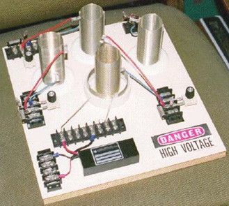 The coil in the centre of the board is a power transmitter made from a Tesla Coil constructed from two Barker & Williamson ready-made coils. Three more of the inner coil are also used as power receivers. The outer, larger diameter coil is a few turns taken from one of their standard coils and organised so that the coil wire length is one quarter of the coil wire length of the inner coil ("L2"). As before, a commercial neon-tube driver module is used to power the "L1" outer coil with high voltage and high frequency. It should be understood that as power is drawn from the local environment each time the power driving the transmitter coil "L1" cycles, that the power available is very much higher at higher frequencies. The power at mains frequency of less than 100 Hz is far, far less than the power available at 35,000 Hz, so if faced with the choice of buying a 25 kHz neon-tube driver module or a 35 kHz module, then the 35 kHz module is likely to give a much better output power at every voltage level. 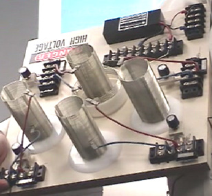 The "L1" short outer coil is held in a raised position by the section of white plastic pipe in order to position it correctly relative to the smaller diameter "L2" secondary coil. 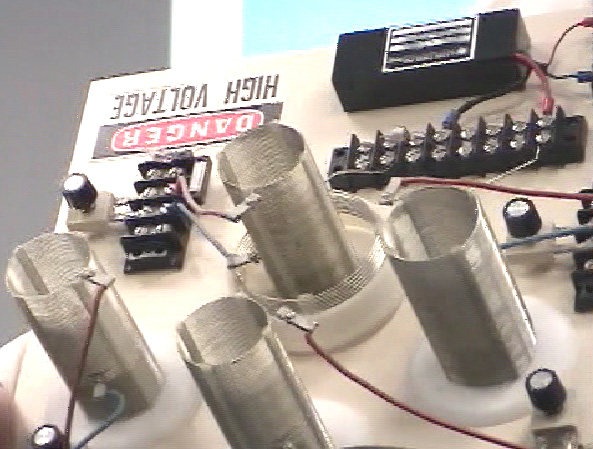 The secondary coils are constructed using Barker & Williamson's normal method of using slotted strips to hold the tinned, solid copper wire turns in place. 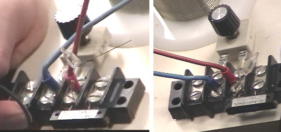 As there are very slight differences in the manufactured coils, each one is tuned to the exact transmitter frequency and a miniature neon is used to show when the tuning has been set correctly. The key feature of this device is the fact that any number of receiver coils can be placed near the transmitter and each will receive a full electrical pick up from the local environment, without altering the power needed to drive the Tesla Coil transmitter - more and more output without increasing the input power - unlimited COP values, all of which are over 1. The extra power is flowing in from the local environment where there is almost unlimited amounts of excess energy and that inflow is caused by the rapidly vibrating magnetic field generated by the central Tesla Coil. While the additional coils appear to just be scattered around the base board, this is not the case. The YouTube video demonstrates that the pick-up of these coils is affected to a major degree by the distance from the radiating magnetic field. This is to do with the wavelength of the signal driving the Tesla Coil, so the coils shown above are all positioned at exactly the same distance from the Tesla Coil. You still can have as many pick-up coils as you want, but they will be mounted in rings around the Tesla Coil and the coils in each ring will be at the same distance from the Tesla Coil in the centre. Each of the pick up coils act exactly the same as the "L2" secondary coil of the Tesla Coil transmitter, each picking up the same level of power. Just as with the actual "L2" coil, each will need an output circuit arrangement as described for the previous device. Presumably, the coil outputs could be connected in parallel to increase the output amperage, as they are all resonating at the same frequency and in phase with each other. Each will have its own separate output circuit with a step-down isolation transformer and frequency adjustment as before. If any output is to be a rectified DC output, then no frequency adjustment is needed, just rectifier diodes and a smoothing capacitor following the step-down transformer which will need to be an air core or ferrite core type due to the high frequency. High voltage capacitors are very expensive. The www.richieburnett.co.uk web site shows various ways of making your own high-voltage capacitors and the advantages and disadvantages of each type. There are two practical points which need to be mentioned. Firstly, as the Don Smith devices shown above feed radio frequency waveforms to coils which transmit those signals, it may be necessary to enclose the device in an earthed metal container in order not to transmit illegal radio signals. Secondly, as it can be difficult to obtain high-voltage high-current diodes, they can be constructed from several lower power diodes. To increase the voltage rating, diodes can be wired in a chain. Suitable diodes are available as repair items for microwave ovens. These typically have about 4,000 volt ratings and can carry a good level of current. As there will be minor manufacturing differences in the diodes, it is good practice to connect a high value resistor (in the 1 to 10 megohm range) across each diode as that ensures that there is a roughly equal voltage drop across each of the diodes:  If the diode rating of these diodes were 4 amps at 4,000 volts, then the chain of five could handle 4 amps at 20,000 volts. The current capacity can be increased by connecting two or more chains in parallel. Most constructors omit the resistors and find that they seem to get satisfactory performance. The impedance of a coil depends on it’s size, shape, method of winding, number of turns and core material. It also depends on the frequency of the AC voltage being applied to it. If the core is made up of iron or steel, usually thin layers of iron which are insulated from each other, then it can only handle low frequencies. You can forget about trying to pass 10,000 cycles per second (“Hz”) through the coil as the core just can’t change it’s magnetic poles fast enough to cope with that frequency. A core of that type is ok for the very low 50 Hz or 60 Hz frequencies used for mains power, which are kept that low so that electric motors can use it. For higher frequencies, ferrite can be used for a core and that is why some portable radios use ferrite-rod aerials, which are a bar of ferrite with a coil wound on it. For higher frequencies (or higher efficiencies) iron dust encapsulated in epoxy resin is used. An alternative is to not use any core material and that is usually referred to as an “air-core” coil. These are not limited in frequency by the core but they have a very much lower inductance for any given number of turns. The efficiency of the coil is called it’s “Q” (for “Quality”) and the higher the Q factor, the better. The resistance of the wire lowers the Q factor. A coil has inductance, and resistance caused by the wire, and capacitance caused by the turns being near each other. However, having said that, the inductance is normally so much bigger than the other two components that we tend to ignore the other two. Something which may not be immediately obvious is that the impedance to AC current flow through the coil depends on how fast the voltage is changing. If the AC voltage applied to a coil completes one cycle every ten seconds, then the impedance will be much lower than if the voltage cycles a million times per second. If you had to guess, you would think that the impedance would increase steadily as the AC frequency increased. In other words, a straight-line graph type of change. That is not the case. Due to a feature called resonance, there is one particular frequency at which the impedance of the coil increases massively. This is used in the tuning method for AM radio receivers. In the very early days when electronic components were hard to come by, variable coils were sometimes used for tuning. We still have variable coils today, generally for handling large currents rather than radio signals, and we call them “rheostats” and some look like this: 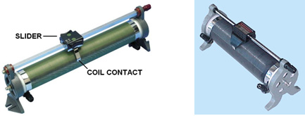 These have a coil of wire wound around a hollow former and a slider can be pushed along a bar, connecting the slider to different winds in the coil depending on it’s position along the supporting bar. The terminal connections are then made to the slider and to one end of the coil. The position of the slider effectively changes the number of turns of wire in the part of the coil which is being used in the circuit. Changing the number of turns in the coil, changes the resonant frequency of that coil. AC current finds it very, very hard to get through a coil which has the same resonant frequency as the AC current frequency. Because of this, it can be used as a radio signal tuner:  If the coil’s resonant frequency is changed to match that of a local radio station by sliding the contact along the coil, then that particular AC signal frequency from the radio transmitter finds it almost impossible to get through the coil and so it (and only it) diverts through the diode and headphones as it flows from the aerial wire to the earth wire and the radio station is heard in the headphones. If there are other radio signals coming down the aerial wire, then, because they are not at the resonant frequency of the coil, they flow freely through the coil and don’t go through the headphones. This system was soon changed when variable capacitors became available as they are cheaper to make and they are more compact. So, instead of using a variable coil for tuning the radio signal, a variable capacitor connected across the tuning coil did the same job:  While the circuit diagram above is marked “Tuning capacitor” that is actually quite misleading. Yes, you tune the radio receiver by adjusting the setting of the variable capacitor, but, what the capacitor is doing is altering the resonant frequency of the coil/capacitor combination and it is the resonant frequency of that combination which is doing exactly the same job as the variable coil did on it’s own. This draws attention to two very important facts concerning coil/capacitor combinations. When a capacitor is placed across a coil “in parallel” as shown in this radio receiver circuit, then the combination has a very high impedance (resistance to AC current flow) at the resonant frequency. But if the capacitor is placed “in series” with the coil, then there is nearly zero impedance at the resonant frequency of the combination:  This may seem like something which practical people would not bother with, after all, who really cares? However, it is a very practical point indeed. Remember that Don Smith often uses an early version, off-the-shelf neon-tube driver module as an easy way to provide a high-voltage, high-frequency AC current source, typically, 6,000 volts at 30,000 Hz. He then feeds that power into a Tesla Coil which is itself, a power amplifier. The arrangement is like this:  People who try to replicate Don’s designs tend to say “I get great sparks at the spark gap until I connect the L1 coil and then the sparks stop. This circuit can never work because the resistance of the coil is too low”. If the resonant frequency of the L1 coil does not match the frequency being produced by the neon-tube driver circuit, then the low impedance of the L1 coil at that frequency, will definitely pull the voltage of the neon-tube driver down to a very low value. But if the L1 coil has the same resonant frequency as the driver circuit, then the L1 coil (or the L1 coil/capacitor combination shown on the right, will have a very high resistance to current flow through it and it will work well with the driver circuit. So, no sparks, means that the coil tuning is off. It is the same as tuning a radio receiver, get the tuning wrong and you don’t hear the radio station. This is very nicely demonstrated using simple torch bulbs and two coils in the YouTube video showing good output for almost no input power: http://www.youtube.com/watch?v=kQdcwDCBoNY and while only one resonant pick-up coil is shown, there is the possibility of using many resonant pick-up coils with just the one transmitter. With a coil (fancy name “inductor” and symbol “L”), AC operation is very different to DC operation. The coil has a DC resistance which can be measured with the ohms range of a multimeter, but that resistance does not apply when AC is being used as the AC current flow is not determined by the DC resistance of the coil. Because of this, a second term has to be used for the current-controlling factor of the coil, and the term chosen is “impedance” which is the feature of the coil which “impedes” AC current flow through the coil. The impedance of a coil depends on it’s size, shape, method of winding, number of turns and core material. It also depends on the frequency of the AC voltage being applied to it. If the core is made up of iron or steel, usually thin layers of iron which are insulated from each other, then it can only handle low frequencies. You can forget about trying to pass 10,000 cycles per second (“Hz”) through the coil as the core just can’t change it’s magnetic poles fast enough to cope with that frequency. A core of that type is ok for the very low 50 Hz or 60 Hz frequencies used for mains power, which are kept that low so that electric motors can use it. For higher frequencies, ferrite can be used for a core and that is why some portable radios use ferrite-rod aerials, which are a bar of ferrite with a coil wound on it. For higher frequencies (or higher efficiencies) iron dust encapsulated in epoxy resin is used. An alternative is to not use any core material and that is usually referred to as an “air-core” coil. These are not limited in frequency by the core but they have a very much lower inductance for any given number of turns. The efficiency of the coil is called it’s “Q” (for “Quality”) and the higher the Q factor, the better. The resistance of the wire lowers the Q factor. Here is a copy of Don Smith’s pdf:  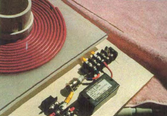 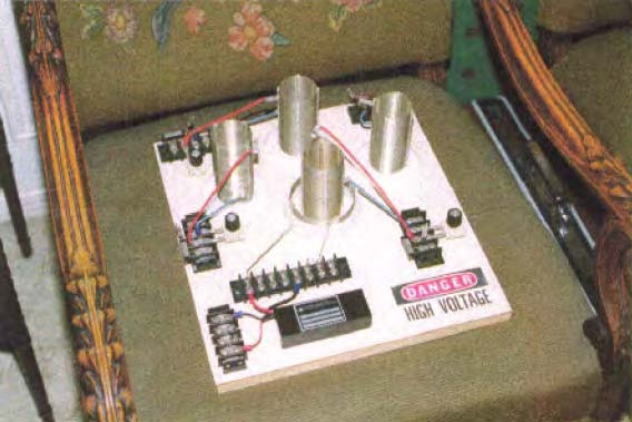 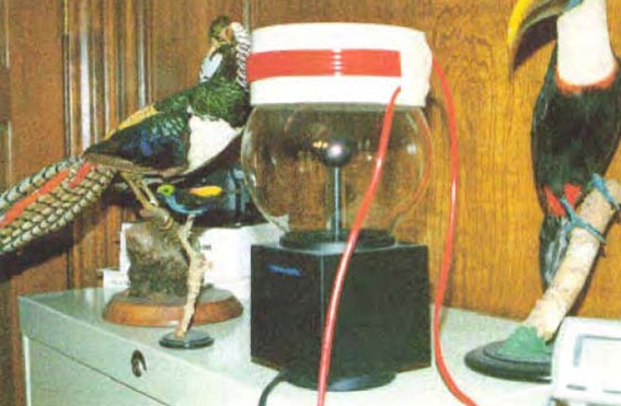 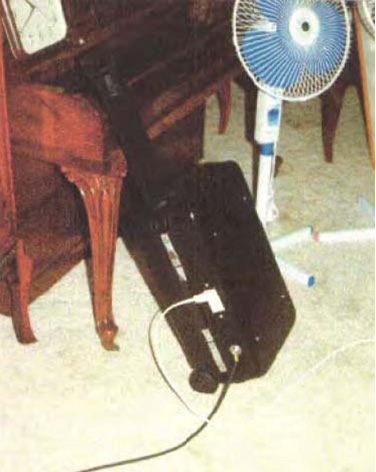 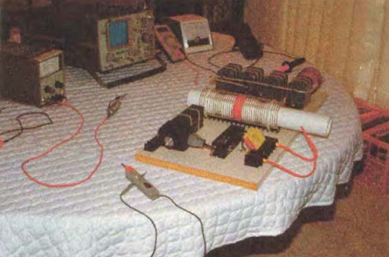 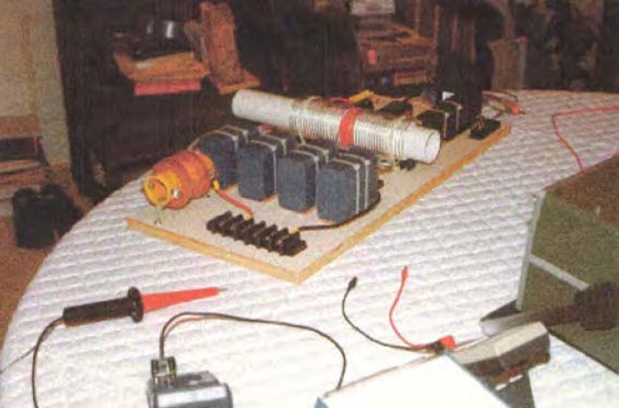 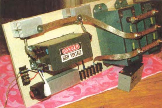 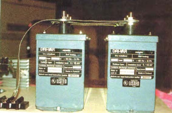 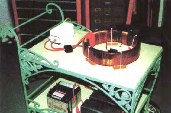 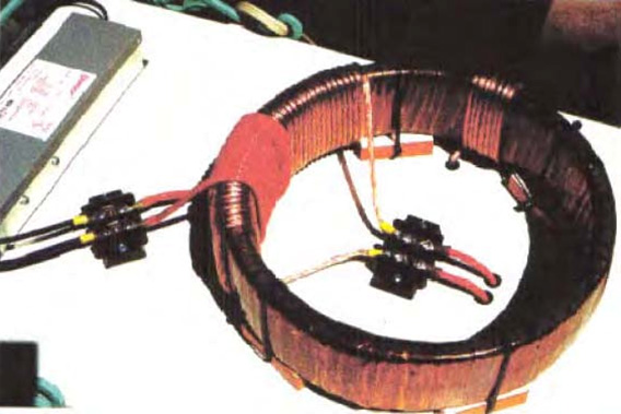     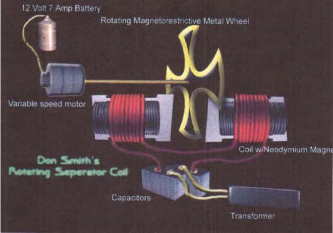 TECHNICAL FIELD: The Invention relates to loaded Dipole Antenna Systems and their Electromagnetic radiation. When used as a transformer with an appropriate energy collector system it becomes a transformer generator. The invention collects and converts energy which, with conventional devices, is radiated and wasted. BACKGROUND ART: An International search of Patent Databases for closely related methods did not reveal any prior Art with an Interest in conserving radiated and wasted magnetic waves as useful energy. DISCLOSURE OF INVENTION: The Invention is a new and useful departure from transformer generator construction, such that radiated and wasted magnetic energy changes into useful electrical energy. Gauss Meters show that much energy from conventional electromagnetic devices is radiated back into the ambient background and wasted. In the case of conventional transformer generators, a radical change in the physical construction, allows better access to the energy available. It is found that creating a dipole and Inserting capacitor plates at right angle to the current flow, allows magnetic waves to change back to useful electrical (coulombs) energy. Magnetic waves passing through the capacitor plates do not degrade and the full impact of the available energy is accessed. One, or many sets of capacitor plates, may be used as desired. Each set of plates makes an exact copy of the full force and effect of the energy present in the magnetic waves. The originating source is not depleted or degraded as is common in conventional transformers. BRIEF DESCRIPTION OF THE DRAWINGS: The Dipole at right angle allows the magnetic flux surrounding it to intercept the capacitor plate, or plates, at right angles. The electrons present are spun in such a way that the electrical component of the electrons is collected by the capacitor plates. Essential parts are the South and North component of an active Dipole. Examples presented here, exist as fully functional prototypes, and were engineer constructed and fully tested for utility by the Inventor. Corresponding parts are utilized in each of the three examples as shown in the Drawings. DRAWING 1 OF 4: VIEW OF THE METHOD N = North and S = South of the Dipole  1. North and South component of the Dipole. 2. Resonate High Voltage induction coil. 3. Dipole's electromagnetic wave emission. 4. Heaviside current component. 5. Dielectric separator for the capacitor plates. 6. For purposes of the drawing, a virtual limit of the electromagnetic wave energy. 7. Capacitor plates with dielectric in between.  Fig.2-A: 1. Hole for mounting Dipole B-1. 2. Resonate high voltage induction coil. 5. Dielectric separator, a thin sheet of plastic separating the capacitor plates 7. Capacitor plates, upper plate is aluminium and lower plate is copper. 8. Battery system, deep cycle. 9. Inverter. Input: Direct Current, output 120 Volts at 60 cycles per second. 10. Connector wires. 11. Output to point of use being the load Fig.2-B N = North and S = South component of the Dipole 1. Metal rod, being soft magnetic metal such as iron. 2. Resonate high voltage induction coil. 10. Connector wires. 11. High Voltage input energy source such as a neon tube transformer. DRAWING 3 OF 4 : Proof of Principle Device, using a Plasma Tube as an active Dipole. N = North and S = South Components of the active Dipole.  5. Dielectric separator of the capacitor plates. 7. Upper capacitor plate: upper plate is aluminium and lower plate is copper. 10. Connector wires. 15. Plasma Tube, 4 feet long and 6 inches in diameter. 16. High Voltage Energy source for the active Plasma Dipole. 17. Connector block: outlet for testing and use. DRAWING 4 OF 4: Manufactures Prototype, Constructed and fully tested.  1. Metal Dipole rod 2. Resonate High Voltage induction coil. 10. Connector wires. 17. Connector block for Input from high voltage energy source. 18. Clamps for upper edge of capacitor packet. 19. Support Device for The Dipole Transformer Generator. 20. Packet of Capacitor Plates. 21. Output connectors of the capacitor, producing energy into a deep cycle battery which then powers the inverter. BEST METHOD OF CARRYING OUT THE INVENTION: The Invention is applicable to any and all electrical energy requirements. The small size and high efficiency makes It an attractive option. It is particularly attractive for remote areas, homes, office buildings, factories, shopping centres, public places, transportation, water systems, electric trains, boats, ships and all things small or great Construction materials are readily available and the skill level required is moderate. CLAIMS: 1. Radiated magnetic flux from the Dipole, when intercepted by capacitor plates at right angles, changes to useful electrical energy. 2. A Device and method for converting for use, normally wasted electromagnetic energy. 3. The Dipole of the Invention is any resonating substance such as Metal Rods, Coils and Plasma Tubes which have interacting Positive and Negative Components. 4. The Resulting Heaviside current component Is changed to useful electrical energy. ABSTRACT An Electromagnetic Dipole Device and Method, wherein, radiated and wasted energy is transformed into useful energy. A Dipole as seen in Antenna Systems is adapted for use with capacitor plates such that the Heaviside Current Component becomes a useful source of electrical energy. 227 W. Airtex Blvd. Houston, Tx. 77090 September 23.2002 Phone: (281)876-9200 Web-site: altenergy-pro.com Fax: (281)876-9216 E-mail: donsm1@earthlink.net Dear Reader: TransWorld Energy is dedicated to improving the Human Condition in the Field of Energy which, at the same time, makes possible Healthy Water and increases the food Supply. A never-ending source of energy found throughout the universe is easily accessed with the minimum of effort and cost. The technology for doing this has been around since the 1820s. Selfish special interests have made sure that the technology remains discredited. People who control the Energy Sources control the World. Extensive research and development by TransWorld and Associates has been progressing for more than 15 years. Numerous successful Energy Producing Devices have been produced and demonstrated throughout the World. Some of these can be viewed by the Web Site located using any major search engine (such as Lycos, Yahoo, Altavista, NorthenLight and more than 2,000 others throughout the World). The Book which You are viewing has more than 40,000 copies in circulation. It has been translated and distributed in all major languages including Japanese, Arabic, Portuguese, French, Italian, Russian, Chinese, German, Spanish and many more. There are seven editions in circulation. An enormous interest is evident in the subject matter. An average of about fifty e-mails per day are received from the ends of the Earth (that is about 1,500 per month). Once the Web Site and the book are viewed, it will become evident that abundant, self- sustainable energy is available everywhere for the taking. This is natural energy which does not harm the environment or those using it. The proper Device for Collecting is all that's required. The Good News is that the problem is solved and with assistance, an ultimate source of energy which is environmentally benign, abundant throughout the universe and inexpensive to capture, is there for the taking. Thank You for your consideration _________________________ Donald L. Smith, CEO 
Description and Function: The Generation of Electrical Power requires the presence of electrons with various methods of stimulation, yielding magnetic and electrical impulses, collectively resulting in Electrical Energy (Power). In place of the mechanical - coils and magnet system, present in conventional electrical power generation, visible moving parts are replaced by resonate magnetic induction, using radio frequency. Transfer of energy by resonate induction is related to the ratio of the square of the cycles per second. The Energy System, presented here, operates at millions of cycles per second verses the conventional 60 C.P.S. This tells us that it has a frequency advantage over conventional methods. This same advantage applies to the amount of electrical energy output. Therefore the Device is small in size and produces large amounts of Electrical Energy. The Electrons acquired, are from the surrounding Air and Earth Groundings, being the same source as in conventional methods. This is accomplished by magnetic resonate radio induction. Applications: This Electrical System adapts nicely to all Energy Requirements. It is a direct replacement for all existing Energy Systems. This includes such things as Manufacturing, Agricultural, Home Usage, Office Complexes, Shopping Centers, Rail Transportation, Automobiles, Electrical Power Grids, Municipalities, Subdivisions, and Remote Areas. Briefly, the only limiting factor is the imagination. Economic Possibilities: No Historical Reference Point exists for a comparison of the Possibilities of this System. One can see from the impacted applications listed above, that the magnitude exceeds any known invention, presently a part of the Human Experience. Present and Future Plans: The Energy System has been in the developmental stage during the past seven years. It is Patent Pending # 08/100,074 with the Patent Office. No prior art exists according to the Patent Office's response. The System is presently being introduced into the World Market. Useful energy occurs as the result of imbalances in the ambient background energy, which is a transient phenomena. In the electrical field, it is a closed system subject to heat death, which severely limits it's utility. The flip side of the electron, produces magnetic waves which are an open system, not subject to heat death. These waves, being unrestricted, are the universal source of energy when unlimited resonate duplicates from this one source are available. Therefore, the key to unlimited energy, is Magnetic Resonance. In order to understand this, requires putting a stake through the Heart of Antique Physics. Non-linear and Open Systems are universally available in Magnetic Resonance Systems, Explosions of any sort [including Atomic Explosions] and Combustibles of any type. Mechanical equivalents would be levers, pulleys and hydraulics. A highly obvious example is the Piano where the Key impacts the one note giving one sound level, which resonates with it's two side keys providing a much higher sound level. Magnetic Resonance Energy clearly amplifies itself, demonstrating more energy out, than in. Ohmic resistance does not apply to Magnetic Resonance which travels unrestricted for great distances, therefore multitudes of electrons are disturbed, and their back-spin translates magnetic into usable electric energy. The right angle component which the magnetic flux provides, translates into useful electrical energy. Taken at right angles, the Magnetic Dipole provides an unlimited source of electrical energy. The writer is recognized world-wide for his knowledge and experience. See his Web Site at altenergy-pro.com . Gravity is a function of spin phenomenon as observed in gravity separation of liquids. When spun, milk and cream separate. Therefore, relative specific gravity is function of mass versus spin. Magnetics and gravity are both spin related. In part, a top levitates when spun. Therefore, spinning magnetic fields are a functional motor source as in flying saucers. ABSTRACT: Technology of New Energy: Developments in the understanding of Electricity, along with Materials which were not previously available, allows the construction of Devices which collect energy in large quantities, from the Earth's Ambient Electrical Background. This Energy is naturally occurring, environmentally benign and is available everywhere. It is available wherever and whenever it is required. New Devices use Resonate Magnetic Waves which replicate upon spinning the locally present electrons, providing multiple duplicate copies of the Energy Present. Each electron when spun yields both magnetic and electric waves in equal proportion. The electrical component is a closed system limited by Ohms Law. The magnetic component is an open system not limited and it replicates multiple copies of the energy present. Special materials and recent developments allow the magnetic energy to reproduce, through resonance, unlimited duplicate copies acquired from the ambient background. These Devices harvest the energy that has been, and is always present universally. Conventional methods consist of coils and magnets systems. Upon moving past each other, the magnetic flux field disturbs electrons which yield electricity, which is collected by the coils system. This is accomplished electronically with the new technology, without any moving parts and the energy is multiplied such that the Device becomes self-sustaining once it is started. This Technology, already presented Worldwide, will be shown at the Conference. Dr. Smith www.altenergy-pro.com e-mail donsml@earthlink.net "Putting a stake through the Heart" and thus removing the mental block created by antique physics is required. Conditions wherein this becomes necessary are non-linearity, resonance and explosions of any sort. Combustibles of any sort such gasoline and atomic explosions are good examples wherein more energy out than in, is obvious. You can add to that the non-linearity found in pulleys, hydraulics, steam power and suchlike. Magnetic resonance is a highly obvious source for multiplying energy output. The sound system present in the piano, demonstrates this very clearly. Energy amplification clearly present in the above, demonstrates the silliness attested to by many Physicists. Ohmic resistance does not apply to magnetic resonance which travels unrestricted for great distances, therefore multitudes of electrons are disturbed, and their back-spin converts from magnetic energy to usable electric energy. These same electrons have been around from the beginning of time and they are undiminished and will remain so until the end of time. Useful Electrical Energy is obtained directly from electron spin induced by incoming magnetic waves, or indirectly through mechanical exchange as in dynamo type devices. Simply put, electron spin converts from magnetic to electrical energy and vice versa. Nature provides grand scale magnetic wave induction throughout the universe, for free. In Electrical Systems, movement is at right angles to the direction of current movement. This explains the rotary movement of the Earth and other related Systems. The rate of Spin for the Earth is known as well as the mass (5.98 x 1024 Kg - "Physics for Scientist and Engineers", by Raymond A. Serway, Saunders College Publishing, 2nd Ed. page 288, Table 14.2), therefore the amount of incoming Electrical Energy which produces this action can be calculated. It can be seen quite easily, that the incoming magnetic wave energy is Vast and Continuous. As an accretion mass, the Earth is an Energy Sink, getting it's energy from elsewhere, being Cosmic, Galactic and Solar. Conversion of incoming magnetic waves into electrical energy provides an unending, inexpensive and environmentally friendly source available to all. Cosmic and Galactic Energy is available twenty four hours per day. Large amounts of this Energy accumulates in the Earth's radiation belts. This Giant Energy Storage, when properly understood, provides a major source of free unending electrical energy. Each of My Inventions plugs into this vast energy source. A perverse, Intentional Ignorance on the part of the Establishment, prevents recognition of the importance of the Energy Systems shown here. Any new system which is favourable towards the masses, is considered as disruptive, and therefore not allowed. Those who have the (Gold) Energy Rule (Golden rule ) Mandated Destruction of all Humanity is not a consideration. This Presenter will remove some of the Fog placed with the intention of preventing the recognition of this unending, environmentally clean, electrical energy Source, which is present everywhere throughout the Universe. The Cost of Harvesting and Using this Free Energy is a function of Human Stupidity. Used to demonstrate electromagnetic radiation between two UC circuits - one a transmitter and the other a receiver. When the 1.5 volt power transmitter is pulsed, the radiated signal is picked up by the remote receiver circuit which then lights up a 70 volt neon lamp. With this apparatus, the student quickly understands some basic principles governing wireless communication, broadcasting, etc. Kit: #10-416 $49.95 THE SCIENCE SOURCE WALDOBORO, MAINE 04572 P.O. BOX 727 Tel. 1-800-299-5469 info@thesciencesource.com  Diagram of transmitter and receiver coils A human is a speck of dust on Earth, the Solar System is a speck of dust in the Galaxy and in turn, the Galaxy is a speck of dust in the Universe (Cosmos). All of these respectively represent vast ambient energy reservoirs. Awareness of the Sun, opens doors into other energy sources. Electromagnetic Energy which is present everywhere throughout the Universe, is accessed by catalytic activity, directly as in Solar Cells or indirectly as by mechanical means. Resonate, Magnetic Waves (Faraday's "Action at a Distance") allow Energy Activation Transfer to remote points of usage. The method of capture and use of this Energy is optional, and therefore it's cost is a function of Human Stupidity (Free-Energy). Direct access is more desirable, and technology transfer from Solar Cell-type Devices provides the Catalyst. Enormously high Ambient Energy Levels are not detected by instruments that use the Ambient Background as a Reference Plane. A spoonful of water lifted from the Ocean does not define the Ocean. Incoming magnetic waves are reflected, Deflected or absorbed. Deflected Magnetic Waves spin electrons sideways producing useful Electrical Energy. Absorbed Wave Energy produces heat, therefore a hot interior for the Earth. In Electrical Systems physical movement is in the direction of current flow, frictional drag from inflow current defines gravity. Accretion masses resulting from Energy Sinks, provide all solid entities with their respective gravitational effect. Increasing the tolerance level for Intellectual Awakening opens Doors of Reality. These doors blink into, and out of existence, and upon recognition, benefit Mankind. Opening some of these Doors, which at the present time are seen through a deep fog, is our purpose. Exploring Unrecognized Energy Sources, which are a Part of the Ambient Background, is another goal. Our Available Instruments do not use reference planes which allow recognition of this energy, as we shall see, vast Energy Sources that totally surround us are available through Technology Transfer. They are inexpensive (Free), fully self-renewable and environmentally benign. Incoming Magnetic Wave Energy with Faraday's "action at a distance" will be looked at closely. Particle Physics will be left for the Astrophysics. Excited Electrons at point "A" the Sun (including the Galaxy and Cosmos) do not travel to point "B" the Earth, however a corresponding action occurs at point "B". The Electrons being disturbed at the Central Power Plant, in the same manner excite the Electrons at Your House, upon switching into an Earth grounding (known as "flipping the switch"). Correspondingly, there are Four Major Power Sources providing enormous amounts of Ambient Background Magnetic Wave Energy. They are The Cosmic, Galactic, Solar and Earth's Ambient Electromagnetic Backgrounds. The Earth's Electromagnetic Field comes from reflection, deflection and absorption as a result of action at a distance from the above. Prescription Physics mandates that the Earth's background is of little interest. When we have Considered the evidence herein, it will become obvious that Special Interest's effort at keeping the People ignorant has, until now, largely succeeded. Information for the entire World is available regarding the Magnetic Flux Background of the Earth's Surface (United State's Geological Survey, Colorado, USA, Office). When examined and properly understood, these Maps yield important information regarding reflection, deflection and absorption of incoming Magnetic Waves, plus action at a distance. When properly understood, these Maps reveal a very large Ambient Electromagnetic Energy Source. This is the Part of the Earth's Energy System that relates to the Bird on the High Voltage Line. When deflected, magnetic flux from electrons changes to electrical flux, providing the Motor System that spins or rotates the Earth. Physical movement by electrical systems is from inflow current movement. What level of current movement is required to spin the Earth? The Earth's Mass is 5.98 x 1024. From this Information, the Watts of Electricity Required may be calculated! Absorbed microwave flux energy heats from the inside out, therefore a hot interior of the Earth results. Water is strongly diamagnetic, and on windless days, ocean waves provide visible Proof of the overhead incoming magnetic flux. From the information above, the Earth's weight and rate of spin allows the calculation of the amount of incoming ambient background energy required. As You can see, it is not inconsequential as Prescription Physics mandates. Astrophysicist are concerned with charged particles that whiz by, once every one hundred years, rather than Wave Phenomenon associated with action at a distance. This highly Active Wave Energy translates into Electrical Energy at point "B". The Galaxy is alive With Energy which is billions of times greater than that of the Sun. Visible Light is a very tiny part of the Electromagnetic Energy Spectrum. Frequencies present in the Galaxy and Cosmos allow Radio Telescope photographs of their existence and magnitude. One such 408 MHz photograph of the Electromagnetic Energy Spectrum shows that the Earth is a tiny speck of dust in this Enormous Ocean of Energy, and can be seen near the left end of the Central High Energy Area. This Energy extends in all directions. Accretion and formation of Planets, Suns and Galaxies are results of energy sinks and variable sized black holes. Mass retains heat, and is cooked from the inside out by the microwave background energy provided by the Universe. Flux movement into energy sinks, provides the frictional force know as gravity. Spinning mass in the presence of incoming flux amplifies the gravitational effect. At present, only Solar Energy is recognized. It is inconsistent, flaky and a very small Part of the Magnetic Wave Energy Present. Technology Transfer from Solar Power provides uncomplicated and inexpensive, direct access to the Other Greater Energy Sources. All Electromagnetic Energy harvesting methods include a Catalyst, a Collector and a Pump. Catalysts include sensitization through doping with certain elements, air and earth groundings. Collectors include temporary storage as in Capacitors, Coils and Transformers. The Pump System includes induced movement onward to the point of use. Conventional rotating coils and magnet systems activate electrons present, such that action at a distance can occur, therefore it is an energy activation pump. In Direct Access Systems such as Solar Cells, the same occurs without mechanical action. Direct access occurs when Magnetic Waves impact a catalyst, spinning the local electrons sideways, producing useful electrical energy. Indirect acquisition of electrical energy by mechanical means is wasteful, troublesome, expensive and degrades the environment. The dynamo is a combination collector and pump of energy which is collected from the Earth's Ambient Energy Background. Generators do not. make electricity, they collect it from the Ambient Background and forward it, as in Faraday's "action at a distance". Energy Conservation Laws relating to these systems, relate to grey areas, and when understood, are excluded because of the existence of External forces, open and non-linear systems as per Einstein. The Knowledge Base just viewed, provides a Direct Understanding of the Requirements for Harvesting of unending, fully renewable, environmentally benign Sources of Electrical Energy. Suggestions for Construction This is the Basic Sonar Power System which permits submarines to see approximately 50 miles distance. What is not commonly known is that it works better at higher frequencies in the Gigahertz range. Any Device that can radiate 50 miles plus, is producing an enormous el ectromagnetic disturbance from a small input into a rod of magnetostrictive material. Disturbing the Earth's Ambient Background plus the strong dipole being produced, turns the magnetostrictive rod into a combination of a receiving antenna and a vastly superior output transformer. The Drawing is only the Key Unit. A power input module and an output inverter circuit (diode bridge plus output transformer) are also required. The metal core and the wire size of the output transformer, plus adjusting the Earth Grounding of the Load, will determine the Amperage. The Ideal rod material is Terfenol-D (check the internet). However a 1.5" diameter 10" long rod, costs over $5,000 each. Less expensive alternatives are obvious. When constructing, use PVC tubing with removable caps. Wind the coils on it and insert the experimental rod. Use only magnetostrictive material. When you get it right, you will have exactly what the Doctor ordered:  Diagram of transmitter and receiver coils Magnetostriction oscillators work by magnetic resonance in a rod of magnetostriction material. This rod serves two purposes: It vibrates at the frequency of resonance oscillation, and it becomes the feedback transformer. Frequency is determined by items 4, 5, 6 and 8. The diameter, length and volume of the rod and output windings, determines the output. Item 2 provides feedback into the system. The negative magnetic character of item 8 plus the windings 2, in reaction to the magnetic flux field provided by 9, increases (amplifies or magnifies) the output. Magnetic permeability is the counterpart of negative resistance. Resonating with negative magnetic resistance, it pumps energy from the Earth's ambient background. Magnetic permeability is the ratio of flux density (Earth's B field) to the magnetizing force (H) in oersteds. Magnetostrictive materials are piezoelectric in character, and have a very high resistance to electrical current flow. Examples are: 1. Permealloy Negative Magnetic Permeability > 80,000 2. Sendust Negative Magnetic Permeability 30,000 -120,000 3. Metglas Negative Magnetic Permeability > 200,000 4. Iron with (34%) Cobalt Magnetic Permeability 13,000 5. New Technology Magnetic Permeability > 1,000,000 1. DIRECT Faraday's "Action at a Distance" incoming magnetic wave conversion to useful electrical energy. This includes Cosmic, Galactic, Solar and Magnets. Technology Transfer is from Solar Cell Technology. 2. INDIRECT Electron Stimulation-Induced Electron Spin Systems, Electron Avalanche Pumping Systems Primitive Indirect Conversion from another form of energy. Coils and Magnet as in Dynamo Systems (Closed Systems). Chemical Systems, Atomic, Pons & Fleischman and etc. Advanced Direct Conversion, Magnetic Wave ( Open Systems ). Ambient Sources Air Core Coil Systems Gaseous Tube Systems, Solid State Marx Generator Avalanche Type Systems. Leyden Bottle Capacitor Types inserted in Lakes and other. Magnet Systems Electron Beam Antenna Systems 3. TRANSFER MECHANISMS Solids - as in metal conductors Gaseous as in radio wave transmission, a form of ionization. Sensitizing of Systems by use of Trace Doping with Radioactive elements, includes metal surfaces. Open Systems, non-linear with external forces. Albert Einstein in a direct quote from his biography states that these are excluded from the conservation of energy laws. Closed Systems Maxwellian Type Systems. Mathematics are predictable requiring deductive reasoning. Ohm's Law is King, and Establishment Intellectuals being comfortable with this, brand all else as a violation of the Laws of Nature by obtaining something for nothing. This is Dishonesty grand mal.  A deep fog pervades the entire Scientific Community with regards to the Significance of the Above Energy Sources. Magnetic Waves convert directly into Electrical Waves (useful electricity). Two sides of the electromagnetic system are always present and never separate. Local electron spin provides (action at a distance) the flip side of the incoming magnetic wave energy. Enormous amounts of incoming magnetic wave energy becomes a part of the Ambient Background, and as such, cannot be measured directly. Reconstruction from indirect information, allows us to establish the actual energy levels which are present. Instruments provided by the Scientific Community measure only point "A" to "B", and when both are ambient, no potential energy is shown. This is the "bird sitting on the million volt power line and sensing nothing" approach. The Earth's actual ambient background has as it's Energy level multi-billions of Volts, which are conveniently and obliviously ignored by the scientific community. When properly understood, this enormous, never-ending source of environmentally-friendly energy becomes available.  Don L. Smith, Energy Consultant At a meeting between J.P. Morgan, Edison and Tesla, Tesla proposed an Electrical Energy System which could he connected into directly, without using a meter. Tesla's Idea of "Free Energy" was not compatible with their thinking. Courtesy of Morgan and Edison, from that day foreword, a complete and total bastardization of the Idea has been in progress. Agents for Morgan and Friends include the U.S. Patent Office and Academia. Academia's bad habit of incestuous quoting of each other, eliminates them as a possibility in cleaning up the mess. This selective ignorance, permeates throughout the study of electricity. Many people, otherwise known as "intellectuals", have a total blackout and become jabbering idiots when "free-energy" is mentioned. The term has been amended to say, "something which was never there is being harvested and that this violates the laws of physics". For the selectively ignorant, this seems the way to run. Those who choose Morgan's drum beat, have severely limited the possibilities built into electricity. This paper will be an exercise in creative understanding, in placing updated knowledge at your disposal. Whether it becomes a useful tool or is selectively ignored is your choice. Electrons are defined as being the practical source of electrical and magnetic energy. The electron as a particle, was postulated by professor J. Thompson in early 1900's. It is now universally accepted that the electron exists and that it is the source of electricity. When the electron is agitated it produces magnetic and negative electrical energy. Physics as it exists today, cannot explain why the electron remains intact and is not diminished by the energy it releases. This is a part of the built-in ignorance provided by the Morgan and Edison Camp. One volts worth of electrons, when cycled, yields one volts worth of electricity. This can be repeated continuously forever and it never deplete or diminishes the electrons in question. They simply return to their air and/or earth source, waiting to do the whole thing again and again. Therefore, electrical energy is available, anywhere and everywhere humans go. People who intercede for profit, set the cost of electrical energy. Otherwise, all electrical energy is free, Morgan and Edison be damned. Improving upon Professor Thompson's postulation, other obvious characteristics can be seen to further define the electron. It has both magnetic and electrical emanations resulting from a right-hand and left-hand spin. Since magnetism and amperage come as one package, this suggest, that electrons in their natural non-ionic state, exist as doublets. When pushed apart by agitation one spins and supplies electricity and the other spins and provides magnetic (amperage) energy. When they reunite, we have Volts x Amperage = Watts. This Idea, until now, has been totally absent from the knowledge base. The number of times that an electron is cycled, sets the collective energy potential present. The electrical equivalent of E = mC2 is E = (Volts x Amperes) x (Cycles Per Second)2. Those who choose, are now free to head for the bushes and make their usual contribution to humanity. Prior to Tesla, there was a large group of people in Europe, who were building resonant coil systems for medical use. Amperage was dangerous in their coil systems. The Tesla Coil is only the Voltage half of their coil system, as will be demonstrated. A short list of those (from 1860 onwards) active in resonate high frequency coil systems include; the Curies, Roentgen, Ruhmkoff, Oudin, Hertz, Levassor, Dumont, D'Arsonval and many others. Peugeot, Panhard-Levassor, Bollee, Renault and others had successful electric automobiles in production using A C. motors. Various electrically-powered airships, including the Dirigible "France" were in service. D'Arsonval, Professor of Experimental Medicine at the College of France, invented the electrocardiograph, oscilloscope, amp and volt meters, thermography and numerous other medical applications of high frequency electricity. As early as 1860, he was building high frequency coil systems, which he used in his experimental work. There is a strong connection between the work of Tesla and the people mentioned above. Electric vehicles of all sorts, dominated until the 1920s, when the electric starter motor made the internal combustion engine practical. Prior to that, upon cranking, it frequently would break the owner's arm. At that point the use of batteries as a source of power was replaced by oil. The establishment's carpet has some rather large lumps under it. Coulomb's and Newton's inverse square law is politely ignored and it's opposite is allowed to have only the most abstract status. Without opposites we have no definition. The source value of a remote flux reading, requires the squaring of the distance, times the remote reading, to obtain the original value. The opposite of this, being the derivations relate to Energy equals Mass times the Velocity constant squared. The electrical equivalent, being Energy equal capacitance times voltage squared and Energy equals induction times amperes squared. Flux lines increase as the law of squares and then activate electron energy which was not previously a part of the sum. The cumulative capacitance and inductance increase as the outer ends of a Tesla coil are approached, and this results in output energy being greater than the input energy present. This Energy is real. It can be safely measured by magnetic flux methods and electrostatic voltmeters, based on the inverse square law As seen above, flux lines result both from induction-henrys-amperage and capacitance-coulombs-volts, and define electrical energy. The non-linearity of this system does not obey Ohm's law, which is replaced with impedance and reactance for alternating current systems. Impedance is the sum of the system's resistance to AC current flow, and this becomes zero at resonance. In resonant induction systems, a cycles-per-second increase, invokes a second round for the law of squares. The degree to which flux lines are present, disturbs an equal amount of electrons, upsetting the ambient background energy, resulting in useful electrical energy being obtained. The frequency at which the disturbance occurs, increases the useful energy available, and it obeys the law of squares. Two square-law components, flux density and frequency are involved. Enter resonance which cancels the resistive effect. Only the electrical energy which is either above or below the ambient level is useful. For the Central U.S. going east to west, ambient as approximated by electro-static voltmeters and flux methods is 200,000 volts on a solar-quiet day. At night time, the ambient energy level drops to about one half of the daytime value. On a solar-active day, it may reach more than five times that of a solar-quiet day. Ambient background energy at the polar regions, is approximately 500,000 volts on a solar-quiet day. The background energy varies as it relates to the North-South component and the East-West continuum. This leaves us with an interesting problem. Electrons, when disturbed, first produce magnetic flux and then produce electrical flux when they spin back to their normal position. Therefore any electron movement produces above ambient energy, being over unity. 1. Current-amperes results from the unequal distribution of negativity (electrons). 2. Electron spin causes electrical current and magnetic lines of force. 3. Magnetic imbalance causes the gravitational effect. This is evidenced in electric motors by magneto-gravitational displacement of mess, which causes the motor to rotate. FIELDS & WAVES * 
* Below 20,000 Cycles Per Second = Fields Above 20,000 Cycles Per Second = Waves (Radio Frequency) Analogous Relationships: 1. Potential Power is present in a bar magnet as shown:  2. The Source of these Electrons being from the Solar Plasma, are non-ionic and occupy all Free Space. They are commonly obtained from Earth and Air Groundings. They exist in Doublet Pairs, one being more negative than the other. The more negative one has a Left Hand Spin. The less negative one has a Right Hand Spin. 3. Resonate Electrical Coil Systems (Tesla ) are Analogous to the System observed in the Bar Magnet (above). The Bloch Wall Area is Located at the base of the L-2 Coil. The Left Spin portion of the coil (Voltage Only ) Coil predominates. The Right hand Spin portion of the coil (Magnetic-Amperage) is mostly absent.  Collection and transfer of energy requires temporary storage, which occurs as capacitors and coils of a resonant circuit are cycled, on and off. The frequency at which the capacitors and coils are pumped, determines the amount of electrical energy that moves onward. The amount of Energy transferred relates directly to the density of lines of flux present. The Kinetic Energy Formula is helpful in establishing the amount of energy present. This formula squares the velocity times mass. In the case of electrical energy, the intensity of voltage and amperes multiplied by the cycles per second, replace the velocity component. Note that the "acceleration" of the Voltage "E" and Amperage "I", which increase as non-linear components, then obeys the Law of Squares. Each unit of increase, causes a squaring of the flux lines present. The amount of energy transfer caused by this increase in flux lines is demonstrated below.  In resonant air-core coil energy transfer, the increase in flux lines present disturbs more electrons than previously, resulting in over-unity energy being present and available. Energy stored, times the cycles per second, represents the energy being pumped by the system. Capacitors and inductors store electrons temporarily. Capacitor formula: W = 0.5 x C x E x Cycles per second where: W = energy in Joules (Watt Seconds ) C = capacitance in farads E = applied potential in volts squared. Inductor (Coil) formula: W = 0.5 x L x I x Cycles per second where: W = energy in Joules (Watt Seconds ) L = inductance in henrys I = current in amperes squared Both one henry, and one farad, equal one volt. The higher the cycles per second, including the squaring of the flux lines, cause a large increase in the amount of energy being produced. The above combined with a resonant energy induction system (where all electrons are moving in the same direction at the same time), make the next move into over-unity practical. The dampening process of conventional electrical power generation, has all the available electrons bouncing randomly, mostly cancelling out each other. In that System, the useful energy available is a very small percentage of the energy which is present. In the resonant induction system, a very high percentage of the energy present is useful. At resonance, (ohms-impedance-Z) becomes zero and all of the energy present is not degraded and becomes available to do useful work. "Ohms" is load or wasted energy, and "amperes" is the rate of that wasting of energy. Using the previous information, if we now apply it to an air-core coil, resonant transformer energy system. L-1 and L-2 coils are now present. L-1 has a smaller number of turns and is several times the diameter of L-2. Input from a 12 volt high-voltage laser driver source, produces 8,000 volts with a low level of wasted energy, pushing amperage into, say, 4 turns of coil L-1. Each turn of the L-1 coil then acquires 2,000 volts of resonant potential. Consequently, each turn of L-2 is then exposed to the electric flux of 2,000 volts. Each turn at the bottom end of L-2 acquires 2,000 volts. The flux lines are squared and are additive as the voltage and amperage progresses towards the top end of L-2's large number of turns. A huge number of additional flux lines which were not previously present become present at the top end of the L-2 coil. These flux lines excite the nearby electrons in it's earth and air and groundings. This high level of excitement above the ambient, causes a large number of electrons which were not previously a part of the energy present, to become available for use. At this point over-unity is present in large amounts. The "bubble gum between the ears" response to this is: "this must be lots of volts but no amperes". Please recall that amperage is wasted energy, and that until that wasting occurs, there are no amperes. A good way to demonstrate this, would be to let the bubble gum crowd put their hands on the high-voltage end of the device while standing on wet ground (a people zapper). Note: don't do this. This over-unity device produces energy at radio frequencies which range into the megahertz band. This allows the device to be small in size, and yet produce large amounts of energy. A megawatt-sized unit will sit comfortably on a breakfast table. This energy is changed to Direct Current and then switched to produce the desired working frequency AC  1. Random movement of electrons in "A" and "B", mostly cancel each other out. This dampening, or wasteful concept of energy, is a source of much pleasure for the establishment. 2. "C" (Volt, Amperes, Reactive "V.A.R."), is the situation where all of the electrons move in the same direction at the same time. This results in near-unity energy output by resonant induction transfer. 3. Resonant induction transfer from one isolated power system, allows other resonant induction systems to duplicate the original source, which in no way diminishes the original source. Air-core coils (isolation-transformers) confirm this when they are a part of one of these functioning systems. A less perfect illustration would be the fact that the number of radio sets tuned to a particular radio transmission, does not alter the power required at the radio transmitter. 4. Resonant induction transfer, disturbs a large number of adjacent electrons which were not a part of the original input power source. The pulsating-pumping effect then draws in the newly available additional electrons into the on-going energy generation system. A near unity energy system of resonant air-core coils and the extra acquired electron-energy source constitute an over-unity system. Useful Electrical Power is Generated when Electrons from Earth and Air Groundings are disturbed by the movement of coils and magnets with reference to each other. The resulting electrical and magnetic energy is then changed to joules [watt-seconds: Volts x Amps x Seconds]. Each forward electron movement results in a magnetic impulse and each return movement causes an electrical impulse. The composite of the electrical energy impulses from these electrons yields useful energy [Power]. Let the above electron movement be represented by a room full of ping pong balls bouncing randomly. Most of the energy present cancels out by random impacts. This is the Classic Under-Unity approach to Electrical Power Generation, sanctioned by the Establishment. In contrast to that, in the Electrical Energy Generation System presented here, the resonant Electrons are all moving in the same direction at the same time. This allows Near-Unity Electrical Power to Develop. This is the room-temperature equivalent of super conductivity. The Energy System presented here, consists of a properly-adjusted and functional resonant air-core coil tank. The magnetic energy is stored in the coil system and the Electrical Energy is stored in capacitors. From Maxwell and others, we know that electrical-related energy has an equal amount of magnetic energy associated with it. "The formula which establishes the Useful Energy of the System": Joules = 0.5 x C x V2 x (Cycles Per Second)2 units: Joules (Volts x Amps x Seconds) Watt Seconds where C = Capacitance in microfarads V = Potential in Volts The transfer of Electrical Power by Resonant Induction is a direct function of the squaring of the cycles per second. For example, square 60 C.P.S. and then square the radio frequency C.P.S.s of the System here presented. Obviously, One Million Cycles per Second transfers more energy than Sixty Cycles per second. The Sanctioned Method of Electrical Power Generation uses the 60 C.P.S. Method. Using 60 C.P.S. and the random scattering of the Electrons System, assures the Establishment of it's desired Under-Unity Goal. This random bouncing of the Electrons is the Ohms of Ohm's Law and is used to establish the rate of dissipation and/or Load [Work]. In the Resonant Tank Induction Energy Transfer System presented here, Impedance [system resistance] replaces the conventional ohm's usage. At Resonance, impedance becomes zero and the full force and effect of the Energy Transfer occurs. This is superconducting conditions at room temperature. At radio frequency the Electrons do not pass through the conductor as they do at lower frequencies. Instead, these Electrons encircle the conductor and are free of the conductor's resistance. Let the Establishments Power Generation System be called 'A" and the System presented here be called "B". With "A": Given 60 C.P.S. at 120 Volts using a 10 microfarad Capacitor: Joules = [0.5 x 0.000010 x 120 squared] x C.P.S. squared (120 x 120 = 14,400) [0.000010 x 14,400 = 0.144] [0.144 x 0.5 = .072] (0.072 x 3,600 = 259.2] Using the Inventor's Resonant Induction System, the Electrical Power available would then be 259.2 Joules [Watt-Seconds]. Using the Establishment's method only permits less than 10 Watt-Seconds of Useful Electrical Energy. "B". Given One Million Cycles per second at 100,000 Volts, using a 10 microfarad Capacitor. Joules = [0.5 x 0.000010 x 100,000]2 x (C.P.S)2 (100,000 x 100,000 = 10,000,000,000) [0.000010 x 10,000,000,000 = 100,000] (100,000 x 0.5 = 50,000] (50,000 x One Million squared = 50,000,000,000,000,000) The useful Electrical Energy available is greater than 50 Mega Watts. Since the Resonant Electrons are non-impacting, all of the Energy is available for direct usage. 1. Induction Energy transfer is enhanced by the squaring of the cycles per second produced by the System. 2. Induction Energy transfer is enhanced by the squaring the input voltage and amperage. 3. The increase of the flux lines occurring from the above, disturbing more electrons, causes more electrical energy to become available. 4. Resonant Induction has all of the Electrons moving unimpeded, resulting in superconductor conditions at room temperature. 5. A smaller amount of energy is used to disturb a larger number of Electrons. Electrons not originally a part of the System then contribute their energy, resulting in a net gain in available usable power. 6. The physical size of the System [Device] is small. The Device described in "B" sits comfortable on a breakfast table. 7. A small energy source is used to start the device and that source remains fully charged at all times by the System. 1. Use of Logarithmic Scales on electrical measurement instruments. Linear measurement works fine where Ohm's Law applies (direct current). In alternating current, ohms are replaced by impedance and the measurements become non-linear. 2. Infinite "Q" at resonance confirms that voltage and amperage is squared, as in the kinetic energy formula. See the formulas of this report. 3. Square waves are clipped infinite "Q"s. 4. Maxwell and others show that magnetic-inductance-amperage and electrical-capacitance-voltage are two sides of the same coin. Magnetic-inductance is directly equal to amperage. Both obey the Law of Squares, which has over-unity built in. 5. Magnetic and electrical flux are present in enormous amounts at the outer ends of an operating Tesla Coil. 6. Ignorance of how to measure and relate magnetic and electrical flux, is the chief weapon of the under-unity gaggle. 7. The Cumulative inductance and capacitance of the Tesla Coil grounds itself out, if not properly utilized. See this report for the temporary energy storage accessible, when properly managed. 8. The Patent Office refers devices related to over-unity to their metering group, which is a sure indication that they are aware and accept the logarithmic measuring devices. This is direct and absolute evidence that they accept the square law as it relates to kinetic energy. This also indicates they are aware that over-unity exists. Since their bureaucratic brain is improperly motivated they continue to badger inventors who are working in the over-unity arena. Their level of intellectual dishonesty is sanctioned by, and is a real part of doing business with, a government which prides itself in being a hooliganistic bureaucracy. 
Donald L. Smith Energy Consultant Energy, energy everywhere and not a Joule to Jounce. Conventional wisdom, when properly tuned will appreciate the nature of energy, as here presented. The basic unit of electricity (the electron) upon encountering a moving magnetic field (or wave) spins, giving off an electric impulse. When this impulse collapses, it spins back to it's natural position, giving off a magnetic impulse. Therefore, magnetic and electric are two sides of the same coin. When the magnetic side is pulsed, it yields electricity and conversely, pulsing of the electrical side yields a magnetic field. Moving one in relation to the other produces useful energy. When done consecutively, each cycle pushes (current) forward, while pulling electrons into the system... in much the same way as a water pump moves water. These electrons are obtained from Earth and air grounding. The word "electric" comes from the Latin word electron "amber". When rubbed, amber develops an electrical charge, which can be transferred to a dissimilar substance. During the seventeenth and eighteenth centuries, a great deal of attention was centered on this attribute of amber. Amber was used to differentiate the non-metals. Carbon-related substances and other non-metals, when subjected to friction, give up negative electrical charges. On the other hand, metals when subjected to friction, simply conduct the charge. It is important to note that approximately 70% of the Earth's exposed crustal portions (surface) consist of silicone-related non-metals (electron donors) and become a direct source of electrical energy when properly agitated. Useful electrical energy can be obtained by grounding into the Earth's non-metal crust and into it's atmosphere as a natural source of electrons. These electrons have accumulated from the solar plasma during the aging of the Earth for more than 4.5 billion years, at a rate exceeding 3.9 exajoules per year This indicates that the Earth's electrical field contains in excess of 17.6 x 10¹⁸ of cumulative exajoules of energy. One exajoule is the approximate energy equivalent of 125 million barrels of oil. The electrical energy in one display of lightning is approximately ten trillion joules. During each 24 hour period, the land portions of Earth's surface yields in excess of 200,000 emissions, which involves more than 2,000 quadrillion watts. C.F. Gauss (1777-1855) and H.C. Oersted (1777-1851) were each separately trying to define the Earth's electrical field with all external influences removed. These external influences being solar-quiet periods and being remote from the land's surface. The air electricity background which they measured varies with latitude. Their European measurements correspond to approximately the latitude of Washington. D C. They were measuring magnetic field flux as an indicator of negative electron energy active and present. A related family of measurement are now presented. Units of measurement used to define flux fields include Gauss (one unit = 100,000 volts), Oersted (one unit = 50,000 volts), Tesla (one unit = 10,000 Gauss) and Gamma (one unit = 1/10,000 of a Gauss). Much confusion exists in electrical related publications about these units. As presented here they are correct with values taken from their original definitions. The entire surface of the Earth has been surveyed by aerial magnetometer, in most cases using gamma or nano teslas. One gamma is the magnetic flux equivalent of 10 active volts of electricity. When the data is corrected for flight height it becomes obvious that there are numerous areas where the gamma readings exceed one trillion gammas. Lightning strikes from the ground up are in that energy range. With knowledge of these electron enriched areas, the quality of Earth grounding, becomes enhanced. The correction necessary for land surface data when acquired from aerial magnetometer maps (using Coulomb's law) requires that the remote distance be squared and then multiplied by the remote reading. As an example, if the remote reading is 1,600 gammas and the flight height being 1,000 feet. Take 1,000 x 1,000 = 1,000,000 x 1,600 gammas = 1.6 trillion gammas x 10 volts = 16 trillion volts equivalent for land surface data. Present day methodology requires mechanical energy in exchange for electrical energy. Once obtained, this energy is subject to Ohm's Law. Present Methodology obtains it's electrical energy from it's non-metal and air groundings. This same energy can be obtained without the wasteful mechanical approach and at a much, much lower cost. Any required amount of electricity is available by resonant induction transfer from the Earth's magnetic and electrical fields. The major difference is in the functioning of Ohm's Law in relation to resonant circuits. In the resonant induction system suggested here, system resistance (Z) becomes zero at resonance. Therefore, Volts and Amperes are equal (V.A.R.) until work (load) is introduced. Each cycling of this resonant induction system pulls in additional electrons from the Earth's electrical field, generating electrical energy in any required amount. In this system, a small amount of electrical energy is used to activate and pull a much larger amount of energy into the system. This electrical advantage corresponds to the pulley and lever of the mechanical world. The electrical system presented here is extremely efficient. Using present methodology as a basis for comparison, with it's 60 cycles per second system. The resonant induction system, cycling at 60 million times per second produces one million times the energy which is produced by the present energy systems. A single small size unit of the resonant induction system has more usable electrical output than a major conventional unit. The radio frequency energy produced is easily changed to Direct Current, and then to the present 60 cycles per second system in preparation for commercial usage. The Patent Pending on this system is #08/100,074, "Electrical Energy Generating System", dated 4 February, 1992. Definitions: One Joule is one watt for one second One Watt is one volt ampere V.A.R. is Volt Amperes Reactive Additional Reading: Electricity and Magnetism by B.I. Bleany and B. Bleany Oxford University Press 1991 ISBN. 0-19-851172-8 Engineering Electromagnetics by W. H. Hayt. Jr. McGraw-Hill 1989 ISBN. 0-07-027406-1 Energy Methods in Electromagnetism by P. Hammond Oxford University Press 1986 ISBN. 0-19-859368-6 Energy in Electromagnetism by H. G. Booker Institution of Electrical Engineers by Peter Peregrinus Ltd. 1982 ISBN 0-900040-59-1 The American Radio Relay League Handbook for 1992 and 1993. 69th and 70th editions. Published by The American Radio Relay League. (For V.A.R. information) ISBN. 0-87259-169-7 Electron Paramagnetic Resonance, Techniques & Applications by R. S. Alger, U. S. Naval Radiological Defence Laboratory, San Francisco, California. Pub. Interscience Lib. Congress #67-20255 Geomagnetic Diagnosis of the Magnetosphere by A. Nishida, University of Tokyo 1978 Pub: Springer-Verlag ISBN. 0-387-08297-2 Energy and The Missing Resource by I. Dostrovsky. Pub: Cambridge University Press 1988 ISBN. 0-521-26592-4 High Voltage Measurement Techniques By A. Schwab, M.I.T.. 1971 I S.B.N. 0-262-19096 Environmental Magnetism by R. Thompson & F. Oldfield Pub: Allen & Unwin, London 1986 ISBN. 0-04-538003-1 Geo-electromagnetic Investigation of the Earth's Crust and Mantle. Translated from Russian, By I. I. Rokityansky. Institute of Geophysics, Kiev, U.S.S R. Pub: Springer-Verlag 1082. ISBN. 3-540-10630-8 Electron Paramagnetic Resonance of Transition Ions by A. Abragam and B. Bleaney Dover Publications, New York, N.Y. 1986 The Electromagnetic Field by A. Shadowitz, Dover Publications, New York, N.Y. Geomagnetism, Several Volumes, Pub. Periodically by J.A. Jacobs, Institute of Earth Studies, Dyfed, U.K. Pub: Academic Press 1989-1990's. Geomagnetism by S. Chapman and J. Bartels, 3 Volumes Oxford University Press, 1940 Physics of Geomagnetic Phenomena, Several Volumes by S. Matsushita and W. H. Campbell National Center for Atmospheric Research, Boulder, Colorado Library of Congress #67-23168 Pub: Academic Press, 1967 Physics Problems and How to Solve Them by C. E. Bennett, Professor Emeritus of Physics. University of Main (Particularly the sections on Electricity and Magnetism, and Units of Measure). Pub: Harper & Row ISBN. 0-06-460203-6 Units and Standards for Electromagnetics By P. Vigoureux, National Physical Laboratory Pub: Springer-Verlag 1071 ISBN. 0-387-91077-8 Surveyor's Guide to Electromagnetic Distance Measurement. Edited by J. J. Saastamoinen, Canada Pub: University of Toronto Press Electromagnetic Distance Measurement by C. D. Burnside Pub: Granada, London 1971 ISBN. 0-258-96793-5 Der Magnetische Kreis "The Magnetic Circuit" By Von Heinz Rieger of Siemens AG. 1970 Berlin and Munchen, Germany I.S.B.N. 3-8009-4719 6 Electronic Modelling of Power Electronic Converters by J. A Ferreira Pub: Kluwer Academic 1989 33 AH Dordrecht, The Netherlands I.S.B.N. 0-7923-9034-2  With alternating electrical current, electrons do not move from point "A" to point "B" as commonly envisioned! Electrical potential (oscillating electrons) at point "A", results in harmonic electron activity at point "B", when the grounding switch (circuit) is closed. That is to say, point "B" supplies it's own electrons and mirrors the activity of point "A". Impulsing (turbulence) by magnetic induction causes electrons to be pulled into the system, which then oscillates. When the magnetic field collapses (becomes absent) the electrical potential returns to it's natural background level. Several major flaws are present in the conventional 60 cycles per second method of electrical power generation and it's iron core transformer system. This system is handcuffed by the inverse relationship of volts to amperes. This represents a stodgy, inflexible inheritance, courtesy of Mr. T.A. Edison and his concept of electrical power generation. Nikola Tesla stood, almost alone, against Edison and managed to prevail with his Alternating Current system. Without the alternating current system, electronic things in the modern sense would not exist. This report will be concerned with some of the extensions and benefits of the alternating current electrical system. This study will limit it's scope to air core coil transformers at radio frequency and upwards. The electrical power produced by this method is inverted to Direct Current and then to Alternating Current as required for popular usage. There are several important advantages of this system over conventional power generation. Start with two coils (separate-apart), one being a reactor coil (L-1) and a second coil (L-2), being the reactant coil. Magnetic field fluxing (off-on of the electrical source) causes inductive reactance of L-1 which replicates by induction in L-2. Pulsing of the magnetic field (from L-1) in the presence of L-2, generates electrical potential. For example, should the L-1 coil have ten turns, with an imposed AC. potential of 1,200 volts. This results in each turn of L-1 acquiring 120 volts of potential. This induced magnetic field, then replicates itself in each turn of the L-2 coil. The L-2 coil may have one or many hundreds of turns. Modern encapsulation techniques makes high frequency and high energy controllable. Let's take another important step in this air-core transformer process. For purpose of discussion, let the value of inductive reactance at 60 cycles per second, equal one. Each time the frequency is doubled, the effectiveness of induction is squared. At about 20,000 Hz, when radio frequency is achieved, the electrons begin spinning free, outside of the inductor and they become increasingly free of the inverse relationship of volt-amperes. From this point on, they replicate by the inductive process as V.A.R.. That is to say, volts and amperes are equal, until resistance (work) is introduced. Therefore, additional, not previously available electrons become incorporated for a very large net gain in potential. This gain is real ! The quality of the grounding system determines the effectiveness of this method of producing electricity. A handy reference to locate the negative grounding areas for power generation can be found in the Aeromagnetic Map Studies of the US Geological Survey. They provide an excellent method for locating the best sites for optimum negative grounding areas. When this method is combined with the induction coil system, already described, it provides an electrical power generating system millions of times more efficient than any known conventional method. This new system ("E.E.S. II") is uncomplicated, physically small and it is inexpensive to build. The technology required for it's construction already exists. Maintenance is near zero, as there are no moving parts. Once operating, this system could last forever. Small mobile E.E.S. II units are already available as replacements for the batteries used in electric automobiles. Larger E.E.S. II units can be provided as a replacement source of power for hotels, office buildings, subdivisions, electric trains, manufacturing, heavy equipment, ships, and generally speaking, any present day application of electrical power. The system consists of three separate modules. Reverse engineering is used in matching the modules to the desired usage. HIGH VOLTAGE INDUCTION TRANSFORMER MODULE: 1. Preferably an off-the-shelf-unit similar to a TV flyback and/or automobile ignition type related coil (transformer). 2. Ratio of input to output may be from less than 1:100 to greater than 1:1,000 A voltage tripler may then be used. 3. A connection allowing the high voltage output to pass onward through the induction coil L-1 and then to it's grounding. AN AIR CORE INDUCTION COIL TRANSFORMER MODULE: 1. There are two coils: the reactor coil L-1 and the reactant coil L-2. L-1 has a high voltage radio frequency capacitor between it and it's grounding. 2. Input into the L-1 inductor is divided by the number of turns in it. The magnetic flux field provided from each turn of L-1 replicates itself as an electrical potential in each turn of L-2. 3. L-2 may have one turn or many hundreds of turns. The net gain depends upon the number of turns in L-2. Output from L-2 is in V.A.R. With this type of output, volts and amperes are the same until work(resistivity) is introduced. THE INVERTER MODULE: 1. Inverts to direct current (D C.) 2. Inverts to alternating current (A C ), as desired. 3. Provides customized output of electrical power ready for designated usage    Speech presented the evening of 23 July. 1994 at the International Tesla Society Convention at Colorado Springs. Colorado: ENERGY CONSULTANT 8110 BENT OAK LANE SPRING. TEXAS 77379 ELECTRICAL ENERGY REFERENCE POINTS Electrical Energy Generating System Patent Pending # 08/100.074. 2/4/92 The word "electric" comes from the Latin word electron "amber". When rubbed, amber develops an electrical charge, which can be transferred to a dissimilar substance. During the seventeenth and eighteenth centuries, a great deal of attention was centered on this attribute of amber. Amber was used to differentiate the non-metals. Carbon-related substances and other non-metals, when subjected to friction, give up negative electrical charges. On the other hand, metals when subjected to friction, simply conduct the charge. It is important to note that approximately 70% of the Earth's exposed crustal portions (surface) consist of silicone related non-metals (electron donors) and therefore becomes a direct source of electrical energy when properly agitated. Useful electrical energy is obtained by grounding into the Earth's non-metal crust and into it's atmosphere as a natural source of electrons. These electrons have accumulated from the solar plasma during the aging of the Earth for more than 4.5 billion years, at a rate exceeding 3.9 exajoules per year. This indicates that the Earth's electrical field contains in excess of 17.6 x 10¹⁸ power of cumulative exajoules of energy. One exajoule is the approximate energy equivalent of 125 million barrels of oil. The electrical energy in one display of lightning is approximately ten trillion joules. During each 24 hour period, the land portions of the Earth's surface yields in excess of 200,000 emissions, which involves more than 2,000 quadrillion watt-seconds of active energy on display. This physical phenomenon indicates that the Earth's crust is an unending source of electrical energy. The surface area involved is a very small portion of the Earth's crust. J.C. Maxwell (1891) suggested that an active electron field gives rise to an associated magnetic field. Therefore, both are present with pulsating current. Early studies, involving observation of compass needles by microscopy, revealed that the needle vibrates as with alternating current. More recent studies by A. Nishida and others, confirm that alternating current is common in the Earth's crust. C.F. Gauss (1777-1855) and H.C. Oersted (1777-1851), both were separately trying to define the Earth's electrical field with all external influences removed. These external influences being solar-quiet periods and being remote from the land's surface. The air electricity background which they measured varies with latitude. Their European measurements correspond to approximately the latitude of Washington, D.C. They were measuring magnetic field flux as an indicator of negative electron energy active and present. A related family of measurement is now presented. Units of measurement used to define flux fields include Gauss (one unit = 100,000 volts), Oersted (one unit - 50,000 volts), Tesla (one unit = 10,000 Gauss) and Gamma (one unit = 1/10,000 th of a Gauss). Much confusion exists in electrical related publications about these units. As presented here, they are correct with values taken from their original definitions. The entire surface of the Earth has been surveyed by aerial magnetometer, in most cases using gamma or nano teslas. One gamma is the magnetic flux equivalent of 10 active volts of electricity. When this data is corrected for flight height, it becomes obvious that there are numerous areas where the gamma readings exceed one trillion gammas. Lightning strikes from the ground up are in that energy range. With knowledge of these electron enriched areas, the quality of Earth grounding, becomes enhanced. The correction necessary for land surface data when acquired from aerial magnetometer maps (using the inverse square law) requires that the remote distance be squared and then multiplied by the remote reading. For example, if the reading is 1,600 gammas and the flight height is 1,000 feet. Take 1,000 x 1,000 = 1,000,000 x 1,600 gammas = 1.6 trillion gammas x 10 volts = 16 trillion volts equivalent for land surface data. Present day methodology requires mechanical energy to be expended in exchange for electrical energy. Any required amount of electricity is available by resonant induction transfer from the Earth's magnetic and electrical fields. Each cycling of this resonant induction system pulls in additional electrons, generating energy in any required amount. A small amount of electrical energy is used to activate and pull into the system a much larger amount of energy.  Electrons become active when placed inside the critical distance allowed by their negativity. Active Electrons provide: 1. Electricity 2. Magnetics 3. Gravitational thrust as in Electric Motors 4. The source of Visible Light 5. It's charge is Negative They move in a closed loop as seen in the Icon for infinity, not in a circle as shown in many books. One half of the loop consist of a magnetic impulse and the return half consist of the electrical impulse. This is seen as the classic sine wave of alternating electrical energy. A flash of light occurs when two electrons suddenly find they are too close together. Daylight results from the impingement of Electrons in the Earth's atmosphere with the Electrons of the Solar Plasma. My Concept of the Forces of Nature differs from the conventional. It consist of a weak and a strong force, each being additionally composed of electrical, magnetic and gravitational (fields and waves). Any two of the three constitute the third member; Gravity "B" of the weak force competes with humans on a daily basis. Gravity "A" of the strong force is the force that holds the Solar System and the Universe in place. Energy from the Electrons represent the weak force. Energy inside the Atom represents the strong force "A". Controlled resonant induction of any two of the three, changes into the third and is the motor that runs the Universe. We see this in the electrically-induced magnetic thrust against gravity in electric motors. Weak force is required to dislodge electrons and strong force (atomic) to dislodge protons. Unless dislodged, these particles are of little value in producing Conventional Electrical Energy. Therefore, in conventional electrical energy production, the particle of importance is the negative electron. Electrons have a "grudging" relationship with other electrons. They like each other, especially at arms length. Like potentials repel each other, and unlike potentials attract. To demonstrate this, take two batteries of the same type, but of a different charge level (unequal potentials). Put the plus and minus ends facing the same direction. Then with a volt meter, measure the electrical potential between the two negative ends and then the two positive ends. It is obvious that the "more negative" moves to the "less negative" is the correct concept for electrical energy generation. Electrical Energy flow consist of a higher concentration of electrons moving to an area of lesser concentration. OHM'S LAW WITH CORRECTIONS: A major obstruction in reference to the correct function of electrical energy is the establishment's incorrect interpretation of Ohm's Law. The corrected version is: Volts = Energy Available (Potential) Ohm = Scattering, dissipation of Energy (Load) Ampere = the rate of, dissipation / scattering of energy It is important to note that Ohm and Ampere are after the fact, and are not decisive except for the dissipation factor. High Voltage at low amperage simply means that the High Voltage is still intact for future usage. In no way is the potential diminished by low amperage. EXAMPLES OF OVERUNITY Dominos did not exist in England when the Laws of Conservation were originally put in place. Otherwise they might have been very different. For example, let us take a long row of upright dominos, (many thousands) and flip number one. The Energy required to flip the first domino must now be added with that of thousands more in order to have a correct assessment. The Electron itself is an excellent example of over-unity. The electron provides various forms of energy continuously throughout eternity and is in no way diminished. It simply cycles through the system and is available thereafter. In Electrical Systems, Electrons active at point "A" are not the same Electrons active at point "B". That is to say, the Electrons activated at the Central Electrical Energy Station are not the ones used at your house. When you ground your system by flipping the wall switch, you use your own electrons. In closed energy systems, electrons communicate with and replicate the activity of the overbalanced potential, when provided with Earth and or Air Groundings. The number of Radio sets and Television sets running at any one time do not diminish, in any way the electrical output of the source station. For example, let now use an Air Coil Resonant Induction System for the purpose of flipping some electrons. The flipping device (reactor coil L-1) is pulsed, which then provides a resonant induction pulse. In turn, this flips the electrons present at the (reactant L-2) Coil. The energy input in L-1 is divided by the number of turns present. The induced magnetic pulsing in turn flips the electrons in each turn of L-2. If more turns are present in L-2 than L-1, there is a net gain in the Energy present, as demonstrated by the dominos above. The farads and henrys of the resonant system provide the resonant frequency when pulsed by an external energy system. A system shunt in the resonant circuit sets the containment level for energy potential. The Induction Process itself provides an excellent example of over-unity. When comparing rate of induction, the cycles per second must be squared and then compared to the square of the second System. Let us then compare the 60 Hz System with my 220 MHz Device. Energy produced at radio frequency has several major advantages over the conventional system. Ohm's Law does not apply to a resonant air-core radio frequency system. For example: When the system is resonant, the following is true:  This is named the V.A.R. ( Volt Amperes Reactive ) System. When compared to the Conventional Under-Unity iron-core transformer system, the results are over- unity. It is strange that mechanical advantage as in pulleys, gears, levers and others which correspond to the electrical advantage above mentioned, are not considered over-unity devices. Let us take a closer look at resonant induction. As an example, let a room full of ping pong balls randomly bouncing at a high speed represent the Conventional method of under-unity energy generation. Suppose that by resonant induction the balls all move in the same direction at the same time. When this occurs a huge amount of energy not previously available is present. The resonant air-core coil system lines up the electrons in such a manner that the energy factor is nearly 100 % , and not the 2% or 3% of Conventional under-unity devices sanction by the establishment. Some other devices where overunity is common would be resonant induction circuits present in conventional radio tubes (high plate voltage), negative-feedback systems found in Op-Amps and possibly others. Useful electrical energy is achieved when the electron density at point "A" becomes greater than at point "B", (being the more-negative moving to the less-negative concept). Coils moving through a magnetic field or vice versa causes this imbalance. The mindset of the professional Electrical Engineer is restricted to non-resonant and iron-core coil resonant systems. Ohm's Law, when applied to resonant air-core induction systems, becomes, system resistivity (impedance, Z). "Z" becomes zero at resonance. Therefore, in this system, volts and amperes are equal until load (resistivity) is introduced. This is called the Volt Ampere Reactive (V.A.R.) System. With impedance being zero, the System grounding is coupled directly into the Earth's immense electrical potential. Efficiency of induction relates to the square of the cycles per second. Compare the ratio of the conventional 60 c.p.s. System and the 220 million plus cycles of my Earth Electrical System II. Electrons which cycle through this system, after being used, are returned intact to their former state for future usage. Electron spin causes electrical current and magnetic lines of force The effect of current, results from the unequal distribution of negativity (electrons). Magnetic imbalance causes the gravitational effect. This is evidenced in electric motors by magnet-gravitational displacement of mass which causes the motor to rotate. The System is an extension of present technology. The System and it's source utilizes magnetometer studies. This System (Earth Electrical System II. "EES.II") utilizes a fully renewable energy source. This System utilizes a non-polluting energy source. This System utilizes an universally available energy source. Endorsement and Certification of The System can be anticipated by States with pollution problems. DONALD L. SMITH Energy Consultant a. Use radio frequency upward (above 20,000 Hz). b. Use natural frequency (coils have both capacitance and inductance), that is match the wire length of the wire in the coil to the desired frequency. c. Wire length is either one quarter, one half or full wave length. d. To obtain the wire length (in feet) use the following: If using one quarter wave length divide 247 by the desired frequency (megahertz range is desirable). If using one half wave length divide 494 by the desired frequency. If using full wave length divide 998 by the desired frequency. 2. Decide number of turns, ratio of increase in number of turns sets the function. In the case of the L-1 coil, each turn divides the input voltage by the number of turns. In the case of L-2 coil, the resulting voltage in each turn of L-1 is induced into each turn of L-2, adding up with each turn. For example if the input into L-1 from a high voltage, low amperage module is 2,400 volts, and L-1, for example, has 10 turns, then each turn of L-1 will have 240 volts of magnetic induction which transfers 240 volts of electricity to each turn of L-2. L-2 may be one turn or many turns, such as 100 to 500 or more turns. At 100 turns, 24,000 volts would be produced. At 500 turns, 120,000 volts would be produced. 3. Decide the height and diameter of the coil system. The larger the diameter of the coil, the fewer turns are required, and the coil has a lesser height. In the case of L-2 this results in lowering the amplification of the induced voltage from L-1. 4. For example, if 24.7 MHz is the desired frequency output from L-2. One quarter wave length would be 247 divided by 24.7 which equals 10 feet of wire. The number of turns will be the amplification factor. The coil may be wound on standard size P.V.C. or purchased from a supplier. The supplier is normally a ham radio supply source. Once the length is determined and the number of turns decided, move to the next step. For example, let each turn of L-1 have 24 volts and desired output of L-2 be 640 volts. Therefore L-2 needs 26.67 turns. It has been determined that the wire length for one quarter wave length is 10 feet. The number of inches in 10 feet is 120. Using Chart "A" supplied look for next higher number of turns showing (being between 20 and 30 turns with a 2 inch diameter coil). This tells us to use a 2" coil. If ready-made as in the case of Barker and Williamson, 10 Canal Street, Bristol, Penna., 215-788-5581, the coils come in standard sizes of 4, 6 and 10 turns per inch. For higher "Q" use wider spacing of the turns. These coils come in a ready-made length of 10 inches. Select from the coil 30 turns and put input clamps on the base of the coil and at 30 turns. For exact determination of the correct position of the output clamp, use an externally grounded voltage probe. The node of maximum intensity, being the natural resonant point. Off the shelf multimeters are not radio frequency responsive. The easiest way to accomplish the above is to get from the hardware store or Radio Shack a voltage detector having a neon bulb system (Radio Shack Cat. No. 272-1100b, NE2-Neon Lamps) will work. With your hand as a ground, move the wire extension of the neon lamp along the coil surface until the neon is brightest. This is the desired point of resonance and it is the optimum connection point. 5. The input power now needs consideration. A 2,400 High Voltage module has been previously selected. This module can be made from a diode bridge or any combination of voltage amplifiers. The one used here is an off-the-shelf type, similar to those used for laser technology. 6. Construction of the input L-1 coil. It has already been decided that there will be 10 turns. The length of the wire here is not critical. Since the L-2 coil is 2-inches in diameter, the next off-the-shelf larger size may be used for L-1. Use a 3 inch diameter off-the-shelf coil which has 10 turns to the inch. Remove (cut) a 10 turn portion from the larger coil. Use an L.C.R. meter and measure the natural farads (capacitance) and henrys (inductance) values of the L-2 coil. Now do the same for the L-1 coil. It will be necessary to put a capacitor across the voltage input of L-1 in order to match the L-1 coil to the L-2 coil. A spark gap across L1 is also required to deal with the return voltage from L-1. A tuneable capacitor of the pad ("trimmer") type for L-1 is desirable. 7. The performance of the L-2 coil can be further enhanced by having an Earth grounding from the base of the coil. The maximum voltage output will be between the base and the top of the L-2 coil. Lesser voltages can be obtained at intermediate points along the length of the L-2 coil. SUPPLY SOURCES 1. HAM RADIO SUPPLY STORES 2. COILS, AIR INDUCTOR IN HOUSTON 3. BAKER AND WILLIAMSON (READY MADE), BRISTOL. PENNA. ALSO R.F. DUMMY LOADS AND WATTMETERS. NOTES  The use of electricity is so commonplace that most people assume that it will always be available on demand. To fully realize our dependence upon electricity, consider the ways in which electricity is being used each day in the home, on the farm and the ranch. Electricity is doing more to increase work efficiency and promote enjoyable living than any other single factor. The use of electricity has grown to the extent that an increasing portion of the home or business budget, is used in paying for this source of energy. 1. Definition of Electricity Electricity can be defined in several ways. The layman defines electricity as a source of energy that can be converted to light, heat, or power. Electrical Engineers define electricity as a movement of electrons caused by electrical pressure or voltage. The amount of energy produced depends on the number of electrons in motion. 2. The Manufacture and Distribution of Electricity Electricity is produced from generators that are run by water, steam, or internal combustion engines. If water is used as a source of power to turn generators, it is referred to as hydroelectric generation. There are a number of this type located in areas where huge dams have been built across large streams. Steam is used as a source of power for generating much of today's electricity. Water is heated to a high temperature, and the steam pressure is used to turn turbines which generate electricity. These are referred to as thermal-powered generators. Fuels used to heat the water are coal, natural gas, and/or fuel oil. Generators at the power plant generate from 13,800 to 22,000 volts of electricity. From the power plant, electricity is carried to a step-up sub-station which, through the use of transformers, increases the voltage from 69,000 to 750,000 volts. This increase in voltage is necessary for the efficient transmission of electricity over long distances. From the step-up sub-station, the electricity is carried on transmission lines to a step-down sub-station which reduces the voltage to 7,200 to 14,000 volts for distribution to rural and city areas.  Transformers at the business or residence reduce the voltage to 120 or 240 volts to supply the meter of the customer:  3. Common Electrical Terms In order to work safely and efficiently with electricity and have the ability to converse on the subject, the following terms should be understood: Ampere (Amp) - A measurement in units of the rate of flow of electrical current. This may be compared with the rate of flow of water in gallons per minute. Example: A 60-watt incandescent lamp on a 120V circuit would pull 1/2 ampere of electricity (60 divided by 120 = 0.5 or 1/2, Formula: Amperes = Watts / Volts Volt (V) - A unit of measure of electrical pressure. A given electrical pressure (V) causes a given amount of electrical current (Amps) to flow through a load of given resistance. Voltage may be compared to water pressure in pounds per square inch in a water system. Common service voltages are 120 volts for lighting and small appliance circuits and 240 volts for heating, air conditioning, and large equipment circuits. Watt (W) - A unit of measure of electrical power. When applied to electrical equipment, it is the rate that electrical energy is transformed into some other form of energy such as light. Watts may be compared to the work done by water in washing a car. (Formula: Volts x Amps = Watts) Kilowatt (KW) - A unit of measurement used in computing the amount of electrical energy used. Kilowatts are determined by dividing the number of watts by 1000 as 1 kilowatt = 1,000 watts. Kilowatt-Hour (KWH) - A measure of electricity in terms of power in kilowatts and time in hours. One KWH is 1000 watts used for one hour. Alternating Current (A.C.) - Electrical current that alternates or changes direction several times per second. The direction current moves depends on the direction in which the voltage forces it. Cycle - The flow of electricity in one direction, the reverse flow of electricity in the other direction, and the start of the flow back in the other direction. The cycles per second are regulated by the power supplier and are usually 60 in America. Most electric clocks are built to operate on the mains frequency. More or fewer cycles per second would cause mains-operated clocks to gain or lose time. The present practice is to use the term Hertz (Hz) rather than "cycles per second".  Direct Current (D.C.) - Electrical current flowing in one direction. Example: electrical circuits in automobiles and tractors. Transformer - A device used to increase or decrease voltage.  Single Phase - The most common type of electrical service or power available to consumers. One transformer is used between the distribution line and the meter. Usually three wires, two "hot" and one neutral, are installed to provide 120V and 240V single-phase service. Single-phase service may also be supplied with a three-phase service. Three-Phase - This type of service is designed especially for large electrical loads. It is a more expensive installation due to three wires and three transformers being required. The important advantage of three-phase power is that the total electrical load is divided among the three phases, consequently, the wire and transformers can be smaller. Other advantages exist in the design of three-phase motors. Short Circuit - A direct connection (before current flows through an appliance) between two "hot" wires, between a "hot" and neutral wire, or between a "hot" wire and ground. Voltage Drop - A reduction of current between the power supply and the load. Due to resistance, there will be a loss of voltage any time electricity flows through a conductor (wire). Factors that influence voltage drop are size of wire, length of wire, and the number of amps flowing. A drop in voltage may cause a loss of heat, light, or the full power output of a motor. It could cause motor burn-out unless the motor is properly protected (time-delay fuse). Fuse - A device used to protect circuits from an overload of current. Circuit Breaker - A device used to protect circuits from an overload of current. May be manually reset. Time-Delay Fuse - A fuse with the ability to carry an overload of current for a short duration without disengaging the contacts or melting the fuse link. Horsepower (hp) - A unit of mechanical power equal to 746 watts of electrical power (assuming 74.6% electric motor efficiency). Motors of one horsepower and above are rated at 1000 watts per hp while motors below one horsepower are rated at 1,200 watts per hp. Conductor - The wire used to carry electricity (typically, copper or aluminum). Copper and aluminum should not be spliced together due to their incompatibility resulting in deterioration and oxidation. Insulator - A material which will not conduct electricity and is usually made of glass, Bakelite, porcelain, rubber, or thermo-plastic. "Hot" Wire - A current-carrying conductor under electrical pressure and connected to a fuse or circuit breaker at the distribution panel. (Color Code: usually black or red) Neutral Wire - A current-carrying conductor not under electrical pressure and connected to the neutral bar at the distribution panel. (Color Code: usually white) Grounding - The connection of the neutral part of the electrical system to the earth to reduce the possibility of damage from lightning and the connection of electrical equipment housings to the earth to minimize the danger from electrical shock. (Color Code: Can be green or bare wire). Underwriters' Laboratory (U.L.) - An American national organization which tests all types of wiring materials and electrical devices to insure that they meet minimum standards for safety and quality. National Electric Code (N.E.C.) - Regulations approved by the National Board of Fire Underwriters primarily for safety in electrical wiring installations. All wiring should meet the requirements of the national as well as the local code. 4. Computing Electrical Energy Use and Cost If an estimate of cost for electricity used is desired, the name plate data on appliances and equipment and an estimate of operating time may be used. The following formulas should be used for determining watts, amps, volts, watt-hours, kilowatt-hours, and cost. Watts = Volts x Amperes Amperes = Watts / Volts Volts = Watts / Amperes Watt-Hours = Watts x Hours of operation Kilowatt-Hours = Watt-Hours / 1000 Cost = Kilowatt-Hours x Local Rate per Kilowatt-Hour (or per "Unit") Example: Local electricity rate per Kilowatt-Hour: 8 cents Equipment plate data: 120 Volts 5 Amps Monthly hours of operation: 10 1. Watts = Volts x Amperes, so Watts = 120 x 5 = 600 watts 2. Watt-Hours = 600 x 10 = 6,000 watt-hours 3. Kilowatt-Hours = 5,000 / 1,000 = 6 kilowatt-hours (or 6 Units) 4. Cost = 6 x 8 = 48 cents 5. Electrical Circuits An Electrical Circuit is a completed path through which electricity flows. Insulated conductors (wires) provide the path for the flow of electricity. A water system and an electrical circuit are similar in many respects. Water flows through pipes and is measured in gallons per minute, and electricity flows through conductors and is measured in amperes. A simple circuit is shown here:  A circuit includes a "hot" wire (red or black) carrying current from the source through a switch, circuit protector (fuse or circuit-breaker), and an appliance. The neutral wire (white) conducts the current from the appliance to the source (ground). There are two methods for connecting devices in a circuit - "in series" or "in parallel". In a series circuit, all of the current must flow through each device in the circuit. Removing any one of the devices in a series circuit will stop the flow of current. In parallel circuits, the load (lights or appliances) are connected between the two wires of the circuit providing an independent path for the flow of current, and removing a lamp has no effect on the other lamps in the circuit. Switches, fuses, and circuit breakers are always connected in series. In most cases, except for some Christmas tree lights, appliances and lights are connected in parallel.  6. 120 Volt and 240 Volt Circuits The 120V circuit has one "hot" and one neutral wire, with the switch and circuit protector in the hot line. The neutral wire from the appliance is connected to the neutral bar in the fuse or breaker box. For safety, the neutral wire should never be broken or interrupted with a switch or fuse.  The voltage in a 120V circuit is measured with a voltmeter with one lead on the hot terminal and the other lead on the neutral bar. The number of amperes flowing may be measured with a clamp-on ammeter by encircling the hot or neutral wire with the jaws of the ammeter.  The 240V circuit has two hot wires and one safety-ground wire. Switches and fuses are installed in the hot lines. The two hot wires arc necessary for the operation of 240V welders and motors. The safety-ground wire, connected to the metal frame of the equipment or motor and to the neutral bar, does not carry current unless a "short" develops in the motor or welder. If a short should occur, one of the circuit protectors will burn-out or open, thus opening the circuit.  The voltage on a 240V circuit is measured by fastening a lead on the voltmeter to each of the hot wires. Voltage between either hot terminal and the neutral bar will be one-half of the voltage between the two hot wires. The number of amperes flowing can be measured by clamping an ammeter around either of the hot wires. 7. Safety Grounding of Electrical Equipment Refer back, to the 240V circuit and note the ground wire from the metal frame to the neutral bar. The following illustration shows proper safety grounding when operating a drill in a 120V circuit. The safety-ground wire may be bare, but a three-wire cable is recommended. Safety-ground wire in three-wire cable is usually green in color. A current-carrying neutral wire should never be used for a safety-ground. Likewise, a safety-ground wire should never be used as a current-carrying hot or neutral wire.  Using grounded receptacles and a safety-ground on all circuits will allow the safety-grounding of appliances when they are plugged into the outlet. An adapter must be used to properly ground appliances connected to receptacles which are not safety-grounded. If an adapter is used, the green pigtail wire must be connected to a known ground to give protection from electrical shock should a short-circuit occur.  A test lamp can be used to check a circuit completed between a "hot" wire and a neutral wire. Use the test lamp to check appliances for shorts. With the appliance plugged into an outlet, touch the appliance frame with one lead of the test lamp while the other lead of the test lamp is grounded to a water or gas pipe. If the test light does not burn, reverse the appliance plug and check with the test lamp again. If the light burns, a short exists (the hot wire is touching the frame of the appliance). Unplug the appliance and repair or discard it. 8. Electrical Circuit Protection Electrical circuits should be protected from an overload of amperes. Too many amperes flowing through an unprotected circuit will generate heat, which will deteriorate or melt the insulation and possibly cause a fire. The number of amperes that a given conductor can safely carry, depends upon the kind and size of wire, type of insulation, length of run in feet, and the type of installation. Charts are available in reference texts giving allowable current-carrying capabilities of various conductors. The four types of circuit protection are: common fuses, fusetrons (time-delay), fustats (two- part time-delay), and circuit-breakers. Fuses are of two basic types: plug, and cartridge. Common fuses contain a link made from a low-temperature melting alloy which is designed to carry current up to the rating of the fuse. Current higher than the amperage rating causes the link to heat above it's melting point. When the fuse "blows", the link melts and opens the circuit.  Fusetrons (time-delay fuses) are made to carry a temporary overload, such as the overload caused by the starting of an electric motor. The fuse, however, still provides protection for the circuit, and a short-circuit will melt the fuse link. If a common fuse is used, the fuse link will melt every time an electric motor starts. The use of a larger ampere common fuse will prevent the "blow" resulting from the temporary overload, but will not provide protection for the motor or the circuit.  Fustats, non-tamperable fuses of the time-delay type, have a different size base and require a special adapter which is screwed into the standard fuse socket. After the adapter is installed, it cannot be removed. For example, the installation of a 15-ampere adapter allows only the use of 15-ampere or smaller fuse.  Circuit breakers eliminate the replacement of fuses and are commonly used even though a circuit breaker box costs more than a fuse box. Circuit breakers are of two types, thermal and magnetic. The thermal breaker has two contacts held together by a bi-metal latch. A current overload causes the bi-metallic strip to become heated, the latch releases, and the points spring open. After the bi-metallic strip cools, the switch is reset and service is restored.  The magnetic breaker has contacts that are held together by a latch which is released by the action of an electromagnet. The amount of current flowing through the circuit will determine the size of the electromagnet. This type of circuit-breaker is reset by moving the toggle switch to the "on" position. The following diagram shows the parts of a circuit breaker.  9. No Fault Grounding Fuses and circuit-breakers are safety devices which limit current (amperage) in a circuit. Their main function is to protect equipment and wiring from overload. Ground fault circuit interrupters (GFI) are designed to protect humans, equipment, and/or electrical systems from injury or damage if electricity flows in an unintended path (a short-circuit). A GFI is a very sensitive device that functions by comparing the current moving in the "hot" wire with that in the neutral wire. If these two currents are not equal, a fault exists, and current is "leaking" out of the circuit. If the difference in current between the two wires is 5/1000 of an ampere or greater, the GFI will open the circuit, shutting off the power and eliminating any shock hazard. The National Electrical Code requires GFl's for all 120V, single phase, 15 and 20 amp receptacles installed outdoors, in bathrooms, and in garages for residential buildings. A GFI is required at construction sites and some other applications. After correcting a circuit fault, the GFI may be reset for further use. A variety of GFI equipment is made for 120 and 240 volt circuits:  REFERENCES: COOPER, ELMER L., AGRICULTURAL MECHANICS: FUNDAMENTALS AND APPLICATIONS. DELMAR PUBLISHERS INC., ALBANY, NEW YORK ELECTRICAL WIRING - RESIDENTIAL, UTILITY BUILDINGS, SERVICE AREAS, AAVIM, ATHENS, GEORGIA. Note: This electrical information does not apply directly to areas outside America and local regulations for electrical supply should be checked. Variations Some people have experimented with Don Smith’s basic ideas and found some interesting things. One of these people is Ukrainian: I. M. Solovey. The translation for his application for a PhD is shown below and thanks is due to Howerd Halay for making this translation: I. M. Solovey, Candidate Ph.D. NUBiP of Ukraine "Berezhany Agrotechnical Institute” LS Chervinsky, PhD National University of Life and Environmental Sciences of Ukraine NP Semenov, engineer NUBiP of Ukraine "Berezhany Agrotechnical Institute” Considered: Existing scientific views do not have a convincing theoretical basis for the phenomenon of excess energy output. Power supply, Inductance, power, high-frequency measuring range, filter, energy. Currently, there is a great deal of information about devices, after which "Activation” in whatever working field; in the process of “relaxation” output energy is in excess of input energy used. For example, in the "production" of thermal energy observed in the oxygen-hydrogen electrolysers for normal and heavy water (Filimonenko V., 1957, S. Jones, 1989), the electric discharger (Chernetskyy A., 1971), vortex heat generators (Potapov Y., 1992). In the late 1980s Stanley Meyer patents "Water Fuel Cell" (WFC) that allows the conversion of ordinary tap water into hydrogen and oxygen with far less expenditure of energy than would be required by conventional electrolysis, and in much greater quantity than expected with simple electrolysis. His explanation of the results is based on the resonant electric field effects on water molecules [2]. Later Don Smith built a number of devices based on Tesla's experiments, mostly with high output power. In his articles, he notes that he repeated each of the experiments found in the Tesla books, and this gave him an understanding of "ambient background energy “[3]. Objective. Repeat one of the above methods of obtaining energy. To test whether these devices really work. For this we implemented the circuit of the Don Smith device from his patent of 1994, where the generator can achieve an output of 15 kW (Fig. 1). I.M. Solovey, LS Chervinsky, N. Semenov, 2011  Fig.1. Schematic of electricity generator of Don Smith (according to his patent from 1994) Basic materials and methods of research. The main element in the schematic of Fig.1 is an air-core transformer with the windings numbered 6 (primary), 6A (optional), 7 (secondary). For the study we prepared Primary L1, secondary L2 and an additional L3 coil according to specifications given in the following table:  To calculate the electromagnetic parameters of the secondary coil L2 we used a program named “Flyback Tesla calculator”. Calculation results: L2 Coil inductance - 1559.9 uH; self capacity - 4.61 pF; Wire Length 73.2 m; number of turns - 457; quality factor - 8492; resonance frequency AC - 1.875 MHz; and 1/4 resonance frequency – 1.024 MHz (Actual Experiment - 1.1 MHz). The study was conducted according to the schematic in Fig.2. Placing of coil windings - as a Tesla transformer: primary on the base of the secondary.  Fig.2. Schematic of windings L1 and L2 Measurement of current was carried out by a DC ammeter on the PSU. Current consumption in the above schematic is 0.3 A. The value of voltage U2 at the output ends of the winding L2 is calculated by the formula: U2 = Um/N1.N2 = 14/8.463 = 810.25 V where Um is the voltage, 14 V; N1 is the number of primary turns and N2 is the number of secondary turns (see. Table). Note. The formula does not take into account the resistance of the transistor’s base-emitter pn junction nor that of the connecting conductors. Experimentally determined values of voltage - largest breakdown in the air gap between the initial winding ends at L2 point of discharge. The magnitude of the voltage was 500-700 Volts. Frequency: 1.1 MHz measured experimentally by the use of a frequency generator. When connecting the circuit (see. Fig. 2) to the constant power supply, power consumption was 0.3 x 14 = 4.2 W and this power can be called a complete network power consumption of 4.7VA. On output of the L2 winding we obtain (at the base of the coil) current of about 0.3 A and a voltage between the two ends of the coil of 700 V which calculates to 0.3 x 700 = 210 VAR. The study of high-energy parameters of the generator power circuit was conducted in Figs. 3 - 6 where a bulb was used as an active load. The magnitude/intensity of lamp brightness determined the output power measurement. Lamps used were various capacities from 0.3 watts to 21 watts. Under the schematic of Fig. 3 switching in various incandescent lamps, for example 0.3 W, did not lead to lighting, although consumption of the circuit energy was 14 x 0.3 = 4.2 watts.  Fig.3. Circuit of the experiment to determine the active power output of the L2 coil We placed an extra coil L3, as in Smith's schematic (Fig. 4). Coil L3 was placed in the upper third of the L2 coil. A 6 volt, 3 watt lamp was connected to the additional coil L3 (see Table) and it showed a subtle glow.  Fig.4. Inserting various incandescent bulbs through additional winding L3. When we inserted a capacitor C2 in series with the winding L2 (Fig. 5) We inserted a 12 volt 21 watt lamp to the L3 coil output. The lamp became brightly lit and in 4 to 5 seconds it burned out. The current consumption was a net 1.2 amps.  Fig.5. Switching incandescent bulb(s) through the additional winding L3 when creating L2-C2 path. An analogous result was obtained when we switched in a tungsten lamp using the schematic in Fig. 6 in a series circuit L2 / C2. A 12 volt 21 watt lamp also burns out in 4 to 5 seconds. The current in the lamp in this configuration was 1.8 - 2.3 Amps.  Fig.6. Schematic: inserting an incandescent lamp in series through L2 and C2. Conclusions The results of exploratory studies confirm the existing scientific thought that the processes of input and output routing/transmission of electricity using high-voltage high-frequency electromagnetic field (radiation) phenomena require further deep theoretical and experimental studies. References 1. Kanarev FM Beginning Phys chemistry microcosm / Kanarev FM [8th ed.]. Krasnodar, 2007. - 750 s. 2. Fominsky LP Rotary generators of free heat. DIY Fominsky LP - Cherkasy: "OKO-Plus". 2003. - 342 s. 3. US Patent No. 08/100074. The phenomena of appearance of excess energy effects have not found a convincing theoretical explanation from the standpoint of existing scientific views. The interesting thing about this paper from Solovey is that the input voltage is so low at a mere 14 volts, although, of course, the output voltage is much higher and is at 1.1 Megahertz. Solovey’s final diagram Fig.6 is interesting in that his 21 watt 12 volt bulb was destroyed in just a few seconds. The measurement of current through the bulb was 2.1 amps while the bulb’s design current is 1.75 amps. That difference is not enough to have destroyed the bulb so rapidly, so the problem will have been that the bulb wattage was exceeded severely. Earlier, the voltage across the coil “L2” was measured at 700 volts, so there may have been as much as that applied to the twelve volt bulb. If 700 volts were applied to the bulb and a current of 2.1 amps flowed through the bulb, then the dissipated power in the bulb would have been as much as 700 x 2.1 = 1470 watts which is 70 times the rating for the bulb and more than a kilowatt! Please don’t be misled by the 14 volt input voltage, this circuit steps up the voltage and it could easily kill you. Making a Solid-State Tesla Coil. As some readers may feel that there is some "black magic" about the neon-driver circuit used by Don to drive the Tesla Coil section of his circuitry and that if a suitable unit could not be purchased then the circuit could not be reproduced or tested, it seems reasonable to show how it operates and how it can be constructed from scratch: The circuit itself is made up of an oscillator to convert the 12-volt DC supply into a pulsating current which is then stepped up to a high voltage by a transformer. Here is a circuit which has been used for this:  The supply for the 555 timer chip is protected against spikes and dips by the resistor "R" and the capacitor "C". The 555 timer chip acts as an oscillator or "clock" whose speed is governed by the two 10K resistors feeding the 440 nF capacitor. The step-up transformer is an ordinary car coil and the drive power to it is boosted by the IRF9130 FET transistor which is driven by the 555 chip output coming from it's pin 3. The output from the (Ford Model T) car coil is rectified by the diode, which needs to have a very high voltage rating as the voltage at this point is now very high. The rectified voltage pulses are stored in a very high-voltage capacitor before being used to drive a Tesla Coil. As a powerful output is wanted, two car coils are used and their outputs combined as shown here:  You will notice that the car coil has only three terminals and the terminal marked "+" is the one with the connection common to both of the coils inside the housing. The coil may look like this: 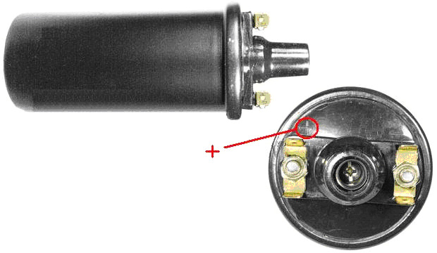 and the "+" is generally marked on the top beside the terminal with the two internal connections running to it. The circuit described so far is very close to that provided by a neon-tube driver circuit and it is certainly capable of driving a Tesla Coil. There are several different way of constructing a Tesla Coil. It is not unusual to have several spark gaps connected in a chain. This arrangement is called a "series spark gap" because the spark gaps are connected "in series" which is just a technical way of saying "connected in a row". In the chapter on aerial systems, you will see that Hermann Plauson uses that style of spark gap with the very high voltages which he gets from his powerful aerial systems. These multiple spark gaps are much quieter in operation than a single spark gap would be. One of the possible Tesla Coil designs uses a pancake coil as the "L1" coil as that gives even higher gain. The circuit is as shown here:  The connection to the pancake coil is by a moveable clamp and the two coils are tuned to resonance by careful and gradual adjustment of that connection, 10 mm at a time (after powering down and discharging the “C1” capacitor). It has been found recently, that connecting two of these (non-ballast resistor) car coils back to back with the plus and minus connections switched over, that the performance is very much improved. It has been suggested that the small self-capacitance of each coil when connected across the other coil, causes a very much higher frequency of operation, giving much sharper voltage spikes which is a very desirable situation in a circuit of this type. This arrangement might be connected like this:  The series spark gap can be constructed in various ways, including using car spark plugs, gas-discharge tubes or neon lamps. The one shown here uses nuts and bolts projecting through two strips of a stiff, non-conducting material, as that is much easier to adjust than the gaps of several spark plugs:  Tightening the bolts which compress the springs moves the bolt heads closer together and reduces all of the spark gaps. The electrical connections can be made to the end tags or to any of the intermediate wire connection straps if fewer spark gaps are required in the chain. Let me remind you again that this is not a toy and very high voltages will be produced. Also, let me stress again that if you decide to construct anything, then you do so entire on your own responsibility. This document is only provided for information purposes and must not be seen as an encouragement to build any such device nor is any guarantee given that any of the devices described in this ebook will work as described should you decide to attempt to construct a replication prototype of your own. Generally, it takes skill and patience to achieve success with any free-energy device and Don Smith's devices are some of the most difficult, especially since he admits quite freely that he does not disclose all of the details. The output capacitor marked "C1" in the circuit diagram above has to be able to handle very high voltages. There are various ways of dealing with this. Don dealt with it by getting very expensive capacitors manufactured by a specialist company. Some home-based constructors have had success using glass beer bottles filled with a salt solution. The outside of the bottles are wrapped in aluminium foil to form one of the contacts of the capacitor and bare wires are looped from deep inside each bottle on to the next one, looping from the inside of one bottle to the inside of the next one, and eventually forming the other contact of the capacitor. While that appears to work well, it is not a very convenient thing to carry around. An alternative is just to stand the bare bottles in a container which is lined with foil which forms the second contact of the capacitor. One method which has been popular in the past is to use two complete rolls of aluminium foil, sometimes called "baking foil", laying them one flat, covering it with one or more layers of plastic cling film and laying the second roll of foil on top of the plastic. The three layers are then rolled up to form the capacitor. Obviously, several of these can be connected together in parallel in order to increase the capacitance of the set. The thicker the plastic, the lower the capacitance but the higher the voltage which can be handled. The November 1999 issue of Popular Electronics suggests using 33 sheets of the thin aluminium used as a flashing material by house builders. At that time it was supplied in rolls which were ten inches (250 mm) wide, so their design uses 14" (355 mm) lengths of the aluminium. The plastic chosen to separate the plates was polythene sheet 0.062 inch (1.6 mm) thick which is also available from a builders merchants outlet. The plastic is cut to 11 inch (280 mm) by 13 inch (330 mm) and assembly is as follows:  The sandwich stack of sheets is then clamped together between two rigid timber sheets. The tighter that they are clamped, the closer the plates are to each other and the higher the capacitance. The electrical connections are made by running a bolt through the projecting ends of the plates. With two thicknesses of plastic sheet and one of aluminium, there should be room for a washer between each pair of plates at each end and that would improve the clamping and the electrical connection. An alternative is to cut a corner off each plate and position them alternatively so that almost no plate area is ineffective. As Don Smith has demonstrated in one of his video presentations, Nikola Tesla was perfectly correct when he stated that directing the discharge from a Tesla Coil on to a metal plate (or in Don's case, one of the two metal plates of a two-plate capacitor where a plastic sheet separates the plates just as shown above), produces a very powerful current flow onwards through a good earth connection. Obviously, if an electrical load is positioned between the plates and the earth connection, then the load can be powered to a high level of current, giving a very considerable power gain. Constructing High-Quality Coils. The Barker & Williamson coils used by Don in his constructions are expensive to purchase. Some years ago, in an article in a 1997 issue of the “QST” amateur radio publication, Robert H. Johns shows how similar coils can be constructed without any great difficulty. The Electrodyne Corporation research staff have stated that off-the-shelf solid tinned copper wire produces three times the magnetic field that un-tinned copper does, so perhaps that should be borne in mind when choosing the wire for constructing these coils. 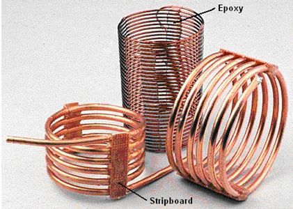 These home-made coils have excellent “Q” Quality factors, some even better than the tinned copper wire coils of Barker & Williamson because the majority of electrical flow is at the surface of the wire and copper is a better conductor of electricity than the silver tinning material. The inductance of a coil increases if the turns are close together. The capacitance of a coil decreases if the turns are spread out. A good compromise is to space the turns so that there is a gap between the turns of one wire thickness. A common construction method with Tesla Coil builders is to use nylon fishing line or plastic strimmer cord between the turns to create the gap. The method used by Mr Johns allows for even spacing without using any additional material. The key feature is to use a collapsible former and wind the coil on the former, space the turns out evenly and then clamp them in position with strips of epoxy resin, removing the former when the resin has set and cured. Mr Johns has difficulty with his epoxy being difficult to keep in place, but when mixed with the West System micro fibres, epoxy can be made any consistency and it can be applied as a stiff paste without any loss of it’s properties. The epoxy is kept from sticking to the former by placing a strip of electrical tape on each side of the former.  I suggest that the plastic pipe used as the coil former is twice the length of the coil to be wound as that allows a good degree of flexing in the former when the coil is being removed. Before the two slots are cut in the plastic pipe, a wooden spreader piece is cut and it’s ends rounded so that it is a push-fit in the pipe. This spreader piece is used to hold the sides of the cut end exactly in position when the wire is being wrapped tightly around the pipe. Two or more small holes are drilled in the pipe beside where the slots are to be cut. These holes are used to anchor the ends of the wire by passing them through the hole and bending them. Those ends have to be cut off before the finished coil is slid off the former, but they are very useful while the epoxy is being applied and hardening. The pipe slots are cut to a generous width, typically 10 mm or more. The technique is then to wedge the wooden spreader piece in the slotted end of the pipe. Then anchor the end of the solid copper wire using the first of the drilled holes. The wire, which can be bare or insulated, is then wrapped tightly around the former for the required number of turns, and the other end of the wire secured in one of the other drilled holes. It is common practice to make the turns by rotating the former. When the winding is completed, the turns can be spaced out more evenly if necessary, and then a strip of epoxy paste applied all along one side of the coil. When that has hardened, (or immediately if the epoxy paste is stiff enough), the pipe is turned over and a second epoxy strip applied to the opposite side of the coil. A strip of paxolin board or strip-board can be made part of the epoxy strip. Alternatively, an L-shaped plastic mounting bracket or a plastic mounting bolt can be embedded in the epoxy ready for the coil installation later on. When the epoxy has hardened, typically 24 hours later, the coil ends are snipped off, the spreader piece is tapped out with a dowel and the sides of the pipe pressed inwards to make it easy to slide the finished coil off the former. Larger diameter coils can be wound with small-diameter copper pipe. The coil inductance can be calculated from: Inductance in micro henrys L = d2n2 / (18d + 40l) Where: d is the coil diameter in inches measured from wire centre to wire centre n is the number of turns in the coil l is coil length in inches (1 inch = 25.4 mm) Using this equation for working out the number of turns for a given inductance in micro henrys:  Patrick Kelly http://www.free-energy-info.com http://www.free-energy-devices.com http://www.free-energy-info.tuks.nl |