|
There is nothing magic about free-energy and by “free-energy” I mean something which produces output energy without the need for using a fuel which you have to buy. Lawrence has been presenting his theory of lead-out energy which indicates that excess energy can be drawn from the environment. The method of producing this effect which he has followed is to create an unbalanced wheel and demonstrate that excess energy is produced. It should be stressed that energy is never created or destroyed and so, when he measures more energy in his device than the energy which he uses to power it, energy is not being created but is instead, being drawn in from the local environment. Lawrence has recently demonstrated a prototype to members of the public: 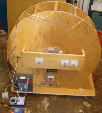 This simple device was demonstrated to have 3.3 times as much output power as the input power needed to make it operate. This is an early prototype which was demonstrated in October 2009 and Lawrence and his helpers are working on to produce more advanced models which have kilowatts of excess electrical power. Mr Tseung remarks: "The Lee-Tseung Lead-Out Energy Theory was first disclosed to the world on 20th December 2004 at Tai Po, in Hong Kong. The Lead-Out Energy Theory basically says that one can lead-out (or bring-in) Energy from the surrounding environment into a Lead-Out Energy Machine. The total Input energy is equal to the sum of the Supplied Energy plus the Lead-Out Energy. For example, if the supplied energy is 100 units and the lead-out energy is 50 units, the device's total Input Energy will be 150 units. This means that the Output Energy can be more than the Supplied Energy of 100 units provided by the person using the device. If we ignore the small loss of energy caused by less than 100% efficiency of the device itself, then the Output Energy will be the whole of the 150 units. If we use 50 of the output energy units and feed back 100 of the output units as the Supplied Energy, then that Supplied Energy can again lead-out another 50 units of excess output Energy for us to use. Thus a Lead-Out Energy Machine can continuously lead-out pollution-free, virtually inexhaustible and readily available energy for us to use. We do not need to burn any fossil fuel or pollute our environment. The two examples of Lead-Out energy which we access are Gravitational and Electron-Motion energy. The Lead-Out Energy theory does not violate the Law of Conservation of Energy. The Law of Conservation of Energy has been used as a roadblock for the so called “Overunity” devices. The patent offices and the scientific establishment routinely dismiss an invention as belonging to the impossible “perpetual-motion machine” category if the inventor cannot identify the energy source of his invention. We got the help of Mr. Tong Po Chi to produce a 60 cm diameter Lead-Out Energy machine in October 2009. The Output Energy of that device is greater than the Input Energy by a factor of 3 times. These results are confirmed by voltmeters and ammeters measuring the Input and Output energies. The Tong wheel has been shown at two Open Shows in Hong Kong (Inno Carnival 2009 and Inno Design Tech Expo) in November and December 2009. Over 25,000 people have seen it. The Better Hong Kong Radio Show has video recorded it, the discussions being conducted in Chinese. At this time, the Tong wheel is at the Radio Studio available for experts to view and examine with their own instruments." The Tong wheel has a diameter of 600 mm and this large size is considered to be important. It has 16 permanent magnets mounted on its rim and 15 air-core coils mounted around it on the stator. There is one position sensor. The coils can be switched to act as drive coils or as energy collection coils:  With this arrangement, if the positions the switches as shown for ten of the fifteen coils shown here, then they act as drive coils. The sensor is adjusted so that the drive circuit delivers a brief energising pulse to those coils just after the magnets have passed their exact alignment position with the coils. This causes them to generate a magnetic field which repels the magnets, thrusting the rotor around. The pulse is very brief, so very little power is needed to accomplish this pulsing. As mentioned before, any number of coils can be switched to provide this driving force. With this particular wheel construction by Mr Tong, the best number has been found to be ten drive coils. The power pick-up is achieved by gathering the electricity generated in some of the coils as the magnets move past them:  In this particular arrangement, five of the coils gather energy while ten provide the drive. For the sake of simplicity, the diagram shows the five collection coils adjacent to each other and while that would work, the wheel is better balanced if the drive coils are evenly spaced out around the rim. For that reason, this switching would actually be selected to give five sets of two drive coils followed by one pick-up coil as that gives a perfectly balanced thrust on the wheel. The two diagrams above are shown separately in order to make it clear how the drive switching and the power pick-up switching are arranged. The full design arrangement and the balanced switching are shown in the following diagram which indicates how the full design is implemented on this particular implementation of the wheel design. The sensor can be a coil feeding a semiconductor switching circuit, or it can be a magnetic semiconductor called a Hall-effect device which can also feed a semiconductor circuit. An alternative would be a reed switch which is a simple mechanical switch encased in an inert gas inside a tiny glass envelope. Suitable switching circuits are described and explained in chapter 12 of this eBook.  Mr Tseung remarks that the large wheel size is due to the fact that the Pulse Force takes time to impart the impulse to the wheel and lead-out energy from the environment into the system. If you want to see this actual wheel, you can email Dr. Alexandra Yuan at ayuan@hkstar.com to make an appointment. The Tong wheel is located at the Better Hong Kong Radio Studio in Causeway Bay, Hong Kong. Just say that you want to see the Lead-Out Energy Machine. The demonstration can be in English or in Chinese. Ideally, there should be a group of at least six visitors with one or more being a qualified engineer or scientist, and you are welcome to bring your own cameras and/or test equipment. It is planned to produce a version which has a 300 watt output, and another with a 5 kilowatt output. Educational kits are also planned. If you decide to replicate this particular design, then to raise the output power level you might consider putting another set of coils around the wheel and either using them as fifteen additional energy pick-up coils or alternatively, pulsing the wheel twice as often. Adding one or more additional rotor discs to the same rotating shaft is also an option and that has the advantage of increasing the rotor weight and improving the effect of the impulses on the rotor. The diameter of the wire used to wind the coils is a design choice which has a wide scope. The thicker the wire, the greater the current and the larger the impulse given to the wheel. The coils are normally connected in parallel as shown in the diagrams. Because of the way magnetic field strength drops off with the square of the distance, it is generally considered good design practice to make the coils one and a half times as wide as they are deep, as indicated in the diagrams above, but this is not a critical factor. This design is, of course, a version of the Adams motor described at the start of this chapter. Although motors of this kind can be built in many different ways, the construction used by Mr Tong has some distinct advantages, so here is a little more detail on how I understand the construction to be carried out.  There are two side pieces which are attached together by sixteen cross timbers, each of which are held in place by two screws at each end. This produces a rigid structure while the construction method is as simple as is possible, using readily available materials which are worked with the most basic of hand tools. The construction also allows the motor to be taken apart completely without any difficulty, transported as a “flat-pack” package and then assembled at a new location. It also facilitates people who want to see the motor taken apart after a demonstration in order to assure themselves that there is no hidden power source. 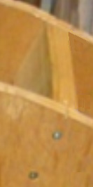 Each of the cross timbers provide a secure mounting platform for an electromagnet and it’s associated switch. In the implementation by Mr Tong, there appears to be just the one rotor, configured as shown above with sixteen permanent magnets mounted in it’s rim. The magnetic poles of these magnets are all orientated in the same direction. That is to say, the magnetic poles facing outwards are all either South or all North poles. It is not critical whether the outward facing poles are North or South as Robert Adams used both arrangements with great success, but having said that, most people prefer to have the North poles facing outwards. Robert has always said that one rotor was enough, but his techniques were so sophisticated that he was able to extract kilowatts of excess power from a single small rotor. For us, just starting to experiment and test a motor of this type, it seems sensible to stick with what Mr Tong has experienced success. However, this build by Mr Tong is not his final motor but just one in a series of continuously improved motors. The following diagram shows an arrangement which has three rotors attached to a single shaft and while you may choose to construct this with just one rotor, if the cross timbers are long enough, then one or two extra rotors can be added in very easily at a later date.  Here, just two of the cross timbers are shown. The electromagnet coils used by Mr Tong are air-core as that type have the least effect on the passing magnets. However, electromagnets with cores tend to be much more power for any given current flowing through them. In theory, the core should be made of lengths of insulated iron wire as that would reduce power loss through eddy currents flowing in the core, but Robert actually recommends solid metal cores, and as he was the most experienced person in this field, paying attention to what he said seems sensible. The core material needs to be a metal which magnetises easily and powerfully, but which does not retain any of its magnetism when the current stops flowing. Not many metals have those characteristics and soft iron is usually recommended. Nowadays, soft iron is not always readily available and so a convenient alternative is the central bolt of a masonry anchor which has excellent properties: 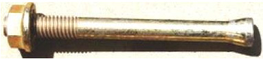 The shaft of the bolt can be cut quite easily with a hacksaw, but be sure to remove (or file down) the head of the bolt as the increase in diameter has a marked effect on the magnetic properties of the electromagnet core if it is left in place. The bolt shown above is a M16 x 147 mm masonry anchor bolt with a bolt diameter of 10 mm. Some makes of dry-ink felt white-board markers have a rigid body which fits the 10 mm bolt exactly and provide an excellent tube for constructing an electromagnet bobbin. With a core in the electromagnets, the rotor gets additional rotating power. Initially, the magnets on the rotor are attracted to the electromagnet cores, giving the rotor a turning force which does not require any current to be supplied. When the rotor magnets are at their closest point to the electromagnet cores, the windings are powered up briefly and that gives the rotor magnets a strong push away, causing the rotor to spin. There are many different designs of simple drive circuits and it is probably worth trying out different types to see which works best with your particular build of motor. In the same way, there are many kinds of collection circuits for taking off some of the excess power generated. The most simple of these is just a diode bridge, perhaps feeding a battery and charging it up for use at a later time. If you get sophisticated with the collection circuit and just take power off for a very short period of time at the correct moment, the cutting off of the current draw, causes a back-EMF magnetic pulse in the collection electromagnet which causes it to give the rotor an extra drive push – both current collection and rotor drive in one combined package.  Here are two of the most simple circuits possible, one for drive and one for power collection. The drive circuit transistor is switched on by a voltage generated in the grey coil by a rotor magnet passing by. The transistor then feeds a large current pulse to the black coil, driving the rotor on its way. The neon and the diode are there to protect the transistor and a physical layout for this circuit might be:  The 1K variable resistor is adjusted to give the best performance and the On/Off switch is optional. More advanced circuits can also be tried and the performance compared. Generally speaking, I would expect a three-rotor version to give a better performance than a single rotor implementation, but experimentation would be needed to verify that. Patrick Kelly http://www.free-energy-info.com http://www.free-energy-devices.com http://www.free-energy-info.tuks.nl |