|
There is nothing magic about free-energy and by “free-energy” I mean something which produces output energy without the need for using a fuel which you have to buy. HHO boosters are popular. They are used to add a hydrogen/oxygen gas mix to the air entering an internal combustion engine. That added mixture improves the quality of the burn of the normal fuel and as a result the miles per gallon performance of the engine is improved, usually by not less than 20% and sometimes by as much as 50% or even more. However, a really major additional benefit is the fact that harmful emissions are normally reduced to zero or very close to zero. Boosters are easy to make as they are only a simple electrolyser which breaks down water into a gas mix which is then normally fed into the air filter of the engine. We will look at two different designs which their designers have very kindly shared with us: The ‘Hotsabi’ Booster Here are the full step-by-step instructions for making a very simple single-cell booster design from “HoTsAbI” - a member of the Yahoo ‘watercar’ forum group. This is a very neat and simple electrolysis booster unit which has raised the average mpg from 18 to 27 (50% increase) on the designer’s 1992 5-litre engined Chevy Caprice.  Caution: This is not a toy. If you make and use one of these, you do so entirely at your own risk. Neither the designer of the booster, the author of this document or the provider of the internet display are in any way liable should you suffer any loss or damage through your own actions. While it is believed to be entirely safe to make and use a booster of this design, provided that the safety instructions shown below are followed, it is stressed that the responsibility is yours and yours alone. The unit draws 15 amps which is easily handled by the existing vehicle alternator. The construction uses ABS (Acrylonitrile Butadiene Styrene) plastic tubing with an electrolyte containing Sodium Hydroxide (NaOH – sold in America as “Red Devil” lye, 1 teaspoon mixed into 8 litres of distilled water) and the gas-mixture produced is fed directly into the air intake filter of the car engine. The electrodes are stainless steel with the negative electrode forming a cylinder around the positive electrode. The circuit is wired so that it is only powered up when the car ignition switch is closed. A relay feeds power to the electrolyser which is three inches (75 mm) in diameter and about 10 inches (250 mm) tall. The electrolyser circuit is protected by a 30-amp circuit breaker. The electrolyser has several stainless steel wire mesh screens above the water surface  The output of the electrolyser is fed to a steam trap, also fitted with several stainless steel wire mesh screens, and then on via a one-way valve into a safety bubbler. The bubbler also has stainless steel wire mesh screens which the gas has to pass through before it exits the bubbler. The gas is then passed through an air-compressor style water trap to remove any remaining moisture, and is injected into the air intake of the vehicle. Although not shown in the diagram, the containers are protected by pop-out fittings which provide extra protection in the extremely unlikely event of any of the small volumes of gas being ignited by any means whatsoever.  The ammeter is used to indicate when water should be added to the electrolyser, which is typically, after about 80 hours of driving and is done through a plastic screw cap on the top of the electrolyser cap (shown clearly in the first photograph). This unit used to be available commercially but the designer is now too busy to make them up, so he has generously published the plans free as shown here. The designer says: please read all of these instructions carefully and completely before starting your project. This project is the construction of an electrolyser unit which is intended to improve the running of a vehicle by adding gases produced by the electrolysis of water, to the air drawn into the engine when it is running. There is no magic about this. The ‘HHO’ gas produced by the electrolysis acts as an igniter for the normal fuel used by the vehicle. This produces a much better burn quality, extracting extra energy from the normal fuel, giving better pulling power, smoother running, cooler engine operation, the cleaning out of old carbon deposits inside the engine and generally extending the engine life. ELECTROLYSER PARTS LIST 1. One 7 inch long x 3 inch diameter piece of ABS tubing cut with square ends - de-burr the edges 2. One 3 inch (75 mm) diameter ABS Plug - clean out the threaded cap 3. One Threaded adaptor DWV 3 inch (75 mm) diameter HXFPT threaded cap ("DWV" and "HXFPT" are male and female threaded sewer-type plastic caps) 4. One 3 inch (75 mm) diameter ABS cap 5. One 4 inch (100 mm) Stainless steel cap screw 1/4 x 20 6. Two stainless steel 1 inch long (25 mm) 1/4 x 20 cap screw 7. One 10/32 inch x 1/4 inch stainless steel screw 8. Five washers and Eight stainless steel nuts 1/4 x 20 9. One piece of stainless steel shimstock 11 inch x 6 inch 0.003 inch thick 10. One piece of stainless steel 14 gauge wire mesh 8 inch x 3 inch 11. One 3/8 inch nylon plug 12. One 1/4 inch x 1/4 inch NPT (National Pipe Tap) barbed fitting 13. Plumbers tape TOOLS LIST 1. Hand drill 2. Tin Snips (for cutting steel mesh and shimstock) 3. 1/4 inch NPT tap and 5/16 inch drill bit 4. 3/8 inch NPT tap and 1/2 inch drill bit 5. 10/32 inch tap and 1/8 inch drill bit 6. One clamp and a piece of 1 inch x 1 inch wood strip 7. Hexagonal key "T-handle" wrench to fit the capscrew 8. Philips screwdriver 9. Small adjustable wrench  Cut and fit shimstock into ABS tubing, 11 inch works well as this gives a 1 inch overlap.  For drilling, use a strip of wood. Be sure that the shimstock is flush with at least one edge of the tube. Use the flush edge as the bottom of the electrolyser.  Clamp securely and drill two 0.165 inch holes, one on either side, perpendicular to each other, as best you can. These holes will be tapped 1/4 inch x 20  The shimstock holes need to be reamed out to accept the capscrew.  Note: This is why 2 holes are drilled (to facilitate assembly). Next, attach the electrode inside the barrel. It is important to us a stainless steel nut inside to seat the capscrew.  Note that the shimstock is flush with the bottom of the tube. Final assembly for the electrodes. Note that the capscrews each have stainless steel nuts inside the barrel to seat to the shimstock. The screw on the left will be used as the Negative battery connection to the cell while the screw on the right merely seats the shimstock.  The upper component is a Threaded Adaptor DWV 3 inch HXFPT. The lower component is a 3 inch ABS Plug, clean out the threaded cap. Prepare the top cap and plug: Drill and tap a 3/8 inch diameter NPT in the centre of the threaded cap (this is the main filling plug). Drill and tap a 1/4 inch NPT on the side (to take the barbed fitting).  Prepare the bottom cap: Drill and tap 1/4 inch x 20 hole in the centre. Install the capscrew with a stainless steel nut. Tighten and install a washer and stainless steel nut outside. This is the Positive battery connection.   This is the finished cell shown here upside down. Assemble the unit using ABS glue.  Next, prepare the stainless steel mesh. Cut it carefully to fit inside the threaded cap. Use at least 3 pieces.  After fitting the mesh tightly into the cap, mount it with a 10/32 inch stainless steel screw on the opposite side to the 1/4 inch tapped hole for the barbed fitting. This is a flame arrestor, so make CERTAIN that the entire inside is covered tightly. Note that the sides wrap up. Turn each layer to cross the grain of the mesh in the successive layers.  Use white "plumber's tape" on all threaded fittings. This unit has raised the average miles-per-gallon performance of my 1992 5-litre Chevy Caprice from 18 to 27 mpg which is a 50% increase. It allows a very neat, professional-looking installation which works very well:  All of the 3/8 inch plastic fittings including one way valves, come from Ryanherco and are made of Kynar to withstand heat. The water trap is from an air compressor. The 3/16 inch tubing or hose is also high-heat type from automatic transmission coolant lines. I use Direct Current and limited with a thermal breaker and LYE mixture adjustment. Comments by Patrick Kelly: This design is very simple to construct, but as it is just a single cell with the whole of the vehicle’s voltage placed across it, a good deal of the electrical power goes in heating the electrolyte rather than making the wanted HHO gas. If there is sufficient space to fit two in, then using two allows you use half the current and that halves the heat generated in the units and doubles the length of time between topping up the unit with water:  Please don’t get the impression that if a small amount of HHO gas produces a very beneficial effect on the running of a vehicle, that adding much more HHO gas will give even better results, as that is not the case. Each vehicle is different and will have a different optimum flow rate of HHO gas and if that optimum rate is exceeded, then although the mpg improvement may actually be reduced rather than increased. If in doubt, start will a low current (with more dilute electrolyte) which will produce less gas and see what the mpg results are. Then try a slightly stronger mix and check the mpg over several gallons of fuel. This will allow you to determine the booster current at which your particular vehicle operates best. This is not a competition to see who can produce the highest gas output, instead, it is a process to find out what the highest mpg your vehicle can give when using this simple booster design. Mixing the electrolyte: Please remember that the sodium hydroxide or ‘lye’ (Lowes store: Roebic ‘Heavy Duty’ Crystal Drain Opener) is a strongly caustic substance which needs to be treated with care. Always store it in a sturdy air-tight container which is clearly labelled "DANGER! - Sodium Hydroxide". Keep the container in a safe place, where it can’t be reached by children, pets or people who won't take any notice of the label. If your supply of sodium hydroxide is in a strong plastic bag, then once you open the bag, you should transfer all its contents to a sturdy, air-tight, plastic storage container, which you can open and close without risking spilling the contents. Hardware stores sell plastic buckets with air tight lids that can be used for this purpose. When working with dry flakes or granules, wear safety goggles, rubber gloves, a long sleeved shirt, socks and long trousers. Also, don’t wear your favourite clothes when handling electrolyte solution as it is not the best thing to get on clothes. It is also good practice to wear a face mask which covers your mouth and nose. If you are mixing solid sodium hydroxide with water, always add the hydroxide to the water, and not the other way round, and use a plastic container for the mixing, preferably one which has double the capacity of the finished mixture. The mixing should be done in a well-ventilated area which is not draughty as air currents can blow the dry hydroxide around. When mixing the electrolyte, never use warm water. The water should be cool because the chemical reaction between the water and the hydroxide generates a good deal of heat. If possible, place the mixing container in a larger container filled with cold water, as that will help to keep the temperature down, and if your mixture should “boil over” it will contain the spillage. Add only a small amount of hydroxide at a time, stirring continuously, and if you stop stirring for any reason, put the lids back on all containers. If, in spite of all precautions, you get some hydroxide solution on your skin, wash it off with plenty of running cold water and apply some vinegar to the skin. Vinegar is acidic, and will help balance out the alkalinity of the hydroxide. You can use lemon juice if you don't have vinegar to hand - but it is always recommended to keep a bottle of vinegar handy. Then there is this second booster design: The ‘Smacks’ Booster The Smack’s Booster is a piece of equipment which increases the mpg performance of a car or motorcycle, and reduces the harmful emissions dramatically. It does this by using some current from the vehicle’s battery to break water into a mixture of hydrogen and oxygen gasses called “HHO” gas which is then added to the air which is being drawn into the engine. The HHO gas improves the quality of the fuel burn inside the engine, increases the engine power, cleans old carbon deposits off the inside of an old engine, reduces the unwanted exhaust emissions and improves the mpg figures under all driving conditions, provided that the fuel computer does not try to pump excess fuel into the engine when it detects the much improved quality of the exhaust. This booster is easy to make and the components don’t cost much. The technical performance of the unit is very good as it produces 1.7 litres of gas per minute at a very reasonable current draw. This is how to make and use it. Caution: This is not a toy. If you make and use one of these, you do so entirely at your own risk. Neither the designer of the booster, the author of this document or the provider of the internet display are in any way liable should you suffer any loss or damage through your own actions. While it is believed to be entirely safe to make and use a booster of this design, provided that the safety instructions shown below are followed, it is stressed that the responsibility is yours and yours alone. The Safety Gear Before getting into the details of how to construct the booster, you must be aware of what needs to be done when using any booster of any design. Firstly, HHO gas is highly explosive. If it wasn’t, it would not be able to do it’s job of improving the explosions inside your engine. HHO gas needs to be treated with respect and caution. It is important to make sure that it goes into the engine and nowhere else. It is also important that it gets ignited inside the engine and nowhere else. To make these things happen, a number of common-sense steps need to be taken. Firstly, the booster must not make gas when the engine is not running. The best way to arrange this is to switch off the current going to the booster. It is not sufficient to just have a manually-operated dashboard On/Off switch as it is almost certain that switching off will be forgotten one day. Instead, the electrical supply to the booster is routed through the ignition switch of the vehicle. That way, when the engine is turned off and the ignition key removed, it is certain that the booster is turned off as well. So as not to put too much current through the ignition switch, and to allow for the possibility of the ignition switch being on when the engine is not running, instead of wiring the booster directly to the switch, it is better to wire a standard automotive relay across the oil pressure sending unit and let the relay carry the booster current. If the engine stops running, the oil pressure drops and if the booster is connected as shown, then this will also power down the booster. An extra safety feature is to allow for the (very unlikely) possibility of an electrical short-circuit occurring in the booster or its wiring. This is done by putting a fuse or contact-breaker between the battery and the new circuitry as shown in this sketch:  If you choose to use a contact-breaker, then a light-emitting diode (“LED”) with a current limiting resistor of say, 680 ohms in series with it, can be wired directly across the contacts of the circuit breaker. The LED can be mounted on the dashboard. As the contacts are normally closed, they short-circuit the LED and so no light shows. If the circuit-breaker is tripped, then the LED will light up to show that the circuit-breaker has operated. The current through the LED is so low that the electrolyser is effectively switched off when the contact breaker opens. This is not a necessary feature, merely an optional extra:  In the first sketch, you will notice that the booster contains a number of metal plates and the current passing through the liquid inside the booster (the “electrolyte”) between these plates, causes the water to break up into the required gas mix. A very important safety item is the “bubbler” which is just a simple container with some water in it. The bubbler has the gas coming in at the bottom and bubbling up through the water. The gas collects above the water surface and is then drawn into the engine through an outlet pipe above the water surface. To prevent water being drawn into the booster when the booster is off and cools down, a one-way valve is placed in the pipe between the booster and the bubbler. If the engine happens to produce a backfire, then the bubbler blocks the flame from passing back through the pipe and igniting the gas being produced in the booster. If the booster is made with a tightly-fitting lid rather than a screw-on lid, then if the gas in the bubbler is ignited, it will just blow the lid off the bubbler and rob the explosion of any real force. A bubbler is a very simple, very cheap and very sensible thing to install. It also removes any traces of electrolyte fumes from the gas before it is drawn into the engine. You will notice that the wires going to the plates inside the electrolyser are both connected well below the surface of the liquid. This is to avoid the possibility of a connection working loose with the vibration of the vehicle and causing a spark in the gas-filled region above the surface of the liquid, and this volume is kept as low as possible as another safety feature. The Design The booster is made from a length of 4-inch diameter PVC pipe, two caps, several metal plates, a couple of metal straps and some other minor bits and pieces. This is not rocket science, and this booster can be built by anybody. A clever extra feature is the transparent plastic tube added to the side of the booster, to show the level of the liquid inside the booster without having to unscrew the cap. Another neat feature is the very compact transparent bubbler which is actually attached to the booster and which shows the gas flow coming from the booster. The main PVC booster pipe length can be adjusted to suit the available space beside the engine. 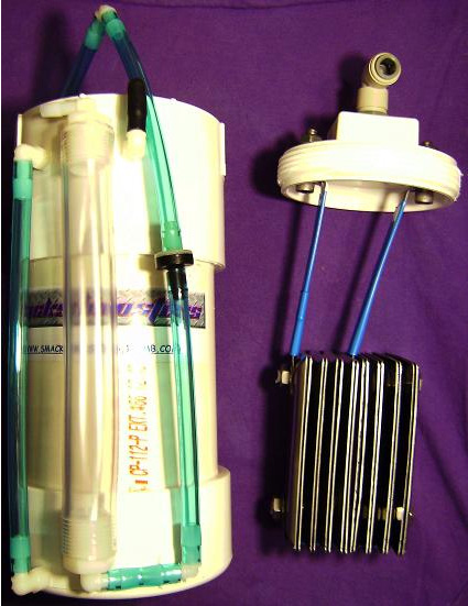 This booster uses cheap, standard electrical stainless steel wall switch covers from the local hardware store and stainless steel straps cut from the handles of a wide range of stainless steel food-preparation ladles: 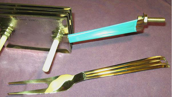 The electrical cover plates are clamped together in an array of eight closely-spaced pairs of covers. The plates are held in a vise and the holes drilled out to the larger size needed. The covers are further treated by being clamped to a workbench and dented using a centre-punch and hammer. These indentations raise the gas output from 1.5 lpm to 1.7 lpm as the both increase the surface area of the cover and provide points from which the gas bubbles can drop off the cover more easily. The more indentations the better. The active surfaces of the plates - that is, the surfaces which are 1.6 mm apart from each other, need to be prepared carefully. To do this, these surfaces are scored in an X-pattern using 36-grade coarse sandpaper. Doing this creates miniature sharp-crested bumps covering the entire surface of each of these plates. This type of surface helps the gas bubbles break away from the surface as soon as they are formed. It also increases the effective surface area of the plate by about 40%. I know that it may seem a little fussy, but it has been found that fingerprints on the plates of any electrolyser seriously hinder the gas production because they reduce the working area of the plate quite substantially. It is important then, to either avoid all fingerprints (by wearing clean rubber gloves) or finish the plates by cleaning all grease and dirt off the working surfaces with a good solvent, which is washed off afterwards with distilled water. Wearing clean rubber gloves is by far the better option as cleaning chemicals are not a good thing to be applying to these important surfaces. 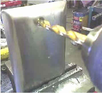 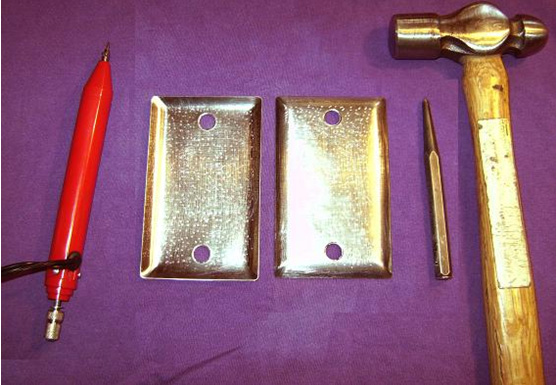 Shown above are typical hand tools used to create the indentations on the plates. The active plate surfaces – that is, the surfaces which are 1.6 mm apart – are indented as well as being sanded. An array of these prepared plates is suspended inside a container made from 4-inch (100 mm) diameter PVC pipe. The pipe is converted to a container by using PVC glue to attach an end-cap on one end and a screw-cap fitting on the other. The container then has the gas-supply pipe fitting attached to the cap, which is drilled with two holes to allow the connecting straps for the plate array to be bolted to the cap, as shown here:   In order to ensure that the stainless steel straps are tightly connected to the electric wiring, the cap bolts are both located on the robust, horizontal surface of the cap, and clamped securely both inside and out. A rubber washer or rubber gasket is used to enhance the seal on the outside of the cap. If available, a steel washer with integral rubber facing can be used.  As the stainless steel strap which connects the booster plates to the negative side of the electrical supply connects to the central section of the plate array, it is necessary to kink it inwards. The angle used for this is in no way important, but the strap should be perfectly vertical when it reaches the plates. The picture above shows clearly the wall plates being used and how the bubbler is attached to the body of the booster with super-glue. It also shows the various pipe connections. The stainless steel switch-cover plates are 2.75 inch x 4.5 inch (70 mm x 115 mm) in size and their existing mounting holes are drilled out to 5/16 inch (8 mm) diameter in order to take the plastic bolts used to hold the plates together to make an array. After a year of continuous use, these plates are still shiny and not corroded in any way. Three stainless steel straps are used to connect the plate array together and connect it to the screw cap of the booster. These straps are taken from the handles of cooking utensils and they connect to the outer two plates at the top and the third strap runs across the bottom of the plate array, clear of the plates, and connects to both outside plates as can be seen in the diagrams. The plates are held in position by two plastic bolts which run through the original mounting holes in the plates. The arrangement is to have a small 1.6 mm gap between each of eight pairs of plates. These gaps are produced by putting plastic washers on the plastic bolts between each pair of plates. The most important spacing here is the 1.6 mm gap between the plates as this spacing has been found to be very effective in the electrolysis process. The way that the battery is connected is unusual in that it leaves most of the plates apparently unconnected. These plate pairs are called “floaters” and they do produce gas in spite of looking as if they are not electrically connected (they are connected through the electrolyte). Stainless steel nuts are used between each pair of plates and these form an electrical connection between adjacent plates. The plate array made in this way is cheap, easy to construct and both compact and robust. The electrical straps are bolted to the screw cap at the top of the unit and this both positions the plate array securely and provides electrical connection bolts on the outside of the cap while maintaining an airtight seal for the holes in the cap.  Another very practical point is that the stainless steel straps running from the screw cap to the plate array, need to be insulated so that current does not leak directly between them through the electrolyte. The same applies to the strap which runs underneath the plates. This insulating is best done with shrink-wrap. Alternatively, good quality tool dip (McMaster Carr part number 9560t71) is an effective method, but if neither of these methods can be used, then the insulating can be done by wrapping the straps in electrical insulating tape. Using that method, the tape is wrapped tightly around the straps, being stretched slightly as it is wrapped. The section running underneath the covers is insulated before the array is assembled.  The PVC housing for the booster has two small-diameter angle pipe fittings attached to it and a piece of clear plastic tubing placed between them so that the level of the electrolyte can be checked without removing the screw cap. The white tube on the other side of the booster is a compact bubbler which is glued directly to the body of the booster using super-glue in order to produce a single combined booster/bubbler unit. The bubbler arrangement is shown here, spread out before gluing in place as this makes the method of connection easier to see.  The half-inch diameter elbows at the ends of the one-inch diameter bubbler tube have their threads coated with silicone before being pushed into place. This allows both of them to act as pressure-relief pop-out fittings in the unlikely event of the gas being ignited. This is an added safety feature of the design. This booster is operated with a solution of Potassium Hydroxide also called KOH or Caustic Potash which can be bought from various suppliers such as: here or here. To get the right amount in the booster, I fill the booster to its normal liquid level with distilled water and add the Hydroxide a little at a time, until the current through the booster is about 4 amps below my chosen working current of 20 amps. This allows for the unit heating up when it is working and drawing more current because the electrolyte is hot. The amount of KOH is typically 2 teaspoonfuls. It is very important to use distilled water as tap water has impurities in it which make a mess which will clog up the booster. Also, be very careful handling potassium hydroxide as it is highly caustic. If any gets on you, wash it off immediately with large amounts of water, and if necessary, use some vinegar which is acidic and will offset the caustic splashes. The booster can be built using different materials to give it a cool look:  And attached to a cool bike:  The final important thing is how the booster gets connected to the engine. The normal mounting for the booster is close to the carburettor or throttle body so that a short length of piping can be used to connect the booster to the intake of the engine. The connection can be to the air box which houses the filter, or into the intake tube. The closer to the butterfly valve the better, because for safety reasons, we want to reduce the volume of HHO gas hanging around in the intake system. You can drill and tap a 1/4" (6 mm) NPT fitting into the plastic inlet tubing with a barbed end for connecting the 1/4" (6 mm) hose. The shorter the run of tubing to the air ductwork of the engine, the better. Again, for safety reasons, we want to limit the amount of unprotected HHO gas. If a long run of 3 feet (1 metre) or more must be used due to space constraints, then it would be a good idea to add another bubbler at the end of the tube, for additional protection. If you do this, then it is better to use a larger diameter outlet hose, say 3/8" or 5/16” (10 mm or 8 mm). Powering your Booster Use wire and electrical hardware capable of handling 20 amps DC, no less. Overkill is OK in this situation, so I recommend using components that can handle 30 amps. Run your power through your ignition circuit, so that it only runs when the vehicle is on. A 30 amp relay should be used to prevent damaging the ignition circuit which may not be designed for an extra 20 amp draw. Make sure to use a properly rated fuse, 30 amps is ideal. You can use a toggle switch if you like for further control. As an added safety feature, some like to run an oil pressure switch to the relay as well, so the unit operates only when the engine is actually running. It is very important that all electrical connections be solid and secure. Soldering is better than crimping. Any loose connections will cause heat and possibly a fire, so it is up to you to make sure those connections are of high quality. They must be clean and tight, and should be checked from time to time as you operate the unit just to be sure the system is secure. Adjusting the Electrolyte Fill your booster with distilled water and NaOH (sodium hydroxide) or KOH (potassium hydroxide) only. No tap water, salt water or rainwater! No table salt or baking soda! These materials will permanently damage the booster! First, fill the booster with distilled water about 2" from the top. Add a teaspoon of KOH or NaOH to the water and then slide the top into place. Do not tighten it for now, but leave the top loose and resting in place. Connect your 12V power supply to the leads and monitor the current draw of the unit. You want 16 amps flowing when the booster is cold. As the water heats up over time, the current draw will increase by around 4 amps until it reaches about 20 amps, and this is why you are aiming for only 16 amps with a cold system. If the current is too high, dump out some electrolyte and add just distilled water. If the current is too low, add a pinch or two at a time of your catalyst until the 16 amps is reached. Overfilling your booster will cause some of the electrolyte to be forced up the output tube, so a liquid level tube was added to monitor electrolyte level. The booster generally needs to be topped off once a week, depending on how long it is in operation. Add distilled water, then check your current draw again. You may observe a drop in current over the course of a few refills, and this is normal. Some of the catalyst escapes the cell suspended in water vapour droplets, so from time to time you may need to add a pinch or two. The water in the bubbler acts to scrub this contaminant out of the gas as well. I highly recommend installing an ammeter to monitor current draw as you operate your booster. Mounting the Booster Choose a well ventilated area in the engine compartment to mount your booster. Since every vehicle design is different, I leave it up to you to figure out the best method to mount it. It must be mounted with the top orientated upwards. Large 5" diameter hose clamps work well, but do not over tighten them or the PVC may deform. I recommend mounting the booster behind the front bumper in the area usually present between it and the radiator. Support the weight of the unit from the bottom with a bracket of your design, then use two hose clamps to secure the unit, one near the top and one near the bottom. Never install the unit in the passenger compartment for safety reasons. Output hose and Bubbler The bubbler on the side of the unit should be filled about 1/3 to 1/2 full of water - tap water is fine for the bubbler. The check valve before the bubbler is there to prevent the bubbler water from being sucked back into the booster when it cools and the gases inside contract. Make sure the bubbler level is maintained at all times. Failure to do so could result in an unwanted backfire explosion. That water inside the bubbler is your physical shield between the stored HHO volume in the generator and the intake of your engine. Install the output hose as close to the carburettor/throttle body as close as possible by making a connection into the intake tube/air cleaner. Try to make the hose as short as possible to reduce the amount of gas volume it contains. I recommend using the same type of 1/4" poly hose that is used on the unit. Here is a list of the parts needed to construct the booster and bubbler if you decide to build it yourself rather than buying a ready-made unit: The Main Parts Needed  Now, having shown how this very effective booster and bubbler are constructed, it should be pointed out that if you use it with a vehicle fitted with an Electronic Control Unit which monitors fuel injection into the engine, then the fuel-computer section will offset the gains and benefits of using this, or any other, booster. The solution is not difficult, as the fuel-computer can be controlled by adding in a little circuit board to adjust the sensor signal fed to the computer from the oxygen sensor built into the exhaust of the vehicle. Ready-built units are available for this or you can make your own. If you want to make your own, then the web site document D17.pdf shows you how and as well, points to Eagle-Research, the suppliers of alternative, ready-made units, also stocked by The Hydrogen Garage. Quite an amount of testing and experimenting has been carried out by many of the people who have made copies of this booster and two variations which have been found to be helpful are shown here: Firstly, in spite of the very restricted space inside the housing, it is possible to introduce two extra wall plates, one at each end of the plate stack. These plates are spaced 1.6 mm apart using plastic washers and this triple-plate group causes an extra voltage drop across the sub-set of three plates. The construction is then as shown here:  The second modification is wrapping the plate array in 4-inch shrink-wrap. This wrapping extends around the sides of the plates and helps by cutting out some of the unwanted electrical leakage paths through the electrolyte. This arrangement is shown here:  Background Information Many people find the plate arrangement of the Smack’s Booster, rather difficult to understand, so this additional section is just to try to explain the operation of the cell. This has nothing to do with actually building or using a Smack’s Booster, so you can just skip this section without missing anything. The Smack's Booster plate arrangement does look confusing. This is mainly because Eletrik has squeezed two identical sets of plates into one container as shown here:  This arrangement is two identical sets of plates positioned back-to-back. To make it easier to understand the operation, let’s just consider just one of the two sets of plates. Here, you have just the electrical Plus linked to the electrical Minus by a set of four pairs of plates in a daisy chain (the technical term is: connected "in series" or "series-connected"). Easily the most electrically efficient way for doing this is to exclude all possible current flow paths through the electrolyte by closing off around the edges of all the plates and forcing the current to flow through the plates and only through the plates. Unfortunately, this is very difficult to do in a cylindrical container and it has the disadvantage that it is difficult to keep the unit topped up with water and difficult to maintain the electrolyte level just below the top of the plates.  So, a compromise is reached where the current flow around and past the plates is combatted by strategic spacing of the plates:  This diagram shows the way that the plates are connected. The red lines show paths of unwanted current flow which produce almost no gas. This wasted current flow is opposed by the useful current flow across gap "A" in the diagram. To favour the flow across the 1.6 mm gap "A", an attempt is made to make the waste flows as long as possible by comparison. This is done by the gap "B" being made as large as possible, limited only by the size of the booster housing. The voltage applied to the cell (13.8 volts when the engine is running) divides equally across the four plate pairs, so there will be one quarter of that voltage (3.45 volts) across each plate pair. If you look again at the original diagram, you will see that there are two of these sets of four plate pairs, positioned back-to-back in the container. Each of these acts separately, except for the fact that there are additional current leakage paths through the electrolyte between the plates of one set and the plates of the second set. There is a steady voltage drop progressively across the array of plates. Remember that they are connected in pairs in the middle due to the metal-to-metal connection created by the steel nuts between the plates:  It is often difficult for people to get the hang of how the voltage drops across a chain of resistors (or matrix of plates). The voltages are relative to each other, so each plate pair thinks that it has a negative electrical connection on one plate and a positive connection on the other plate.  For example, if I am standing at the bottom of a hill and my friend is standing ten feet up the hill, then he is ten feet above me. If we both climb a hundred feet up the mountain and he is at a height of 110 feet and I am at a height of 100 feet, he is still ten feet above me. If we both climb another hundred feet up the mountain and he is at a height of 210 feet and I am at a height of 200 feet, he is still ten feet above me. From his point of view, I am always ten feet below him. The same thing applies to these plate voltages. If you one plate is at a voltage of +3 volts and the plate 1.6 mm away from it is at a voltage of +6 volts, then the 6 volt plate is 3 volts more positive than the 3 volt plate, and there is a 3 volt difference across the gap between the two plates. The first plate looks to be 3 volts negative to the 6 volt plate when it “looks” back at it. You can also say that the +3 volt plate is 3 volts lower than the +6 volt plate, so from the point of view of the +6 volt plate, the +3 volt plate is 3 volts lower down than it, and it therefore “sees” the other plate as being at -3 volts relative to it. In the same way, my friend sees me as being at -10 feet relative to him, no matter what height we are on the mountain. It is all a matter of being "higher up" whether in terms of height above sea level on a mountain or in terms of higher up in voltage inside a booster. Now, having shown how this booster and bubbler are constructed, it should be pointed out that if you use it with a vehicle fitted with an Electronic Control Unit which monitors fuel injection into the engine, then the fuel-computer section will offset the mpg gains and benefits of using this, or any other, booster. The solution is not difficult, as the fuel-computer can be controlled by adding in a little circuit board to adjust the sensor signal fed to the computer from the oxygen sensor built into the exhaust of the vehicle, to allow for the improved quality of the fuel being burnt in the engine. This is necessary because the exhaust will be so much cleaner than it used to be, that the computer will think that the engine is being starved of fuel (which it most definitely isn’t. With a booster, the engine runs cleaner, cooler and more smoothly and it has enhanced pulling power called “torque”. Ready-built units are available for correcting the oxygen sensor signal for the improved situation, or alternatively, you can make your own. Patrick Kelly http://www.free-energy-info.com http://www.free-energy-devices.com http://www.free-energy-info.tuks.nl |