|
There is nothing magic about free-energy and by “free-energy” I mean something which produces output energy without the need for using a fuel which you have to buy. People are familiar with the concept of powering a light from a battery and then recharging the battery using a solar panel or a wind-powered generator. However, we really want to be able to recharge the battery when there is no daylight and no wind. What I personally would like is a light which shines whenever I switch it on and which uses a battery which I never have to recharge. While that sounds a bit far fetched, it is actually achievable if the battery is recharged when I am asleep. Let’s see what can be achieved using the knowledge which we already have. In the November 1999 edition of the magazine “Everyday Practical Electronics”, Mr Z. Karparnik showed one of the most simple and robust circuits ever produced. He called it the “Joule Thief” and originally it was intended to light a 3-volt Light-Emitting Diode using a dry cell battery which had been exhausted and run down to 0.5 volts or so. The Joule Thief circuit is very, very simple, using just one transistor, one resistor and one coil. Mr Karparnik wound his coil with just a short length of wire, making just a few turns on a tiny, scavenged toroid. The circuit looks like this:  The circuit oscillates automatically and it generates a much higher voltage than that of the supply battery, and while it can most certainly light an LED which can’t be lit by the battery on its own, the circuit can do much more than that. It is not necessary to wind the coil on a ring as a simple paper cylinder is perfectly adequate, with a 1-volt battery generating a 19-volt output. The circuit was adapted by Bill Sherman to charge a second battery as well as lighting an LED. Bill adapted the circuit like this:  I have used a circuit of this type (minus the LED) to charge a “1.2V NiMh” rechargeable battery of 2285 maHr capacity from 0.6 volts to 1.34 volts in just one hour. The drive battery started out with a voltage of 1.34 volts and ended up with a voltage of 1.29 volts (which is generally considered to be fully charged). We live in a massive energy field and so the extra energy flowing into the circuit came from the excess energy of our local environment. With a paper cylinder coil, the circuit is like this:  The circuit has a minor weakness in that if the drive battery has a voltage greater than that of the charging battery plus the voltage drop across the diode, then the drive battery feeds current directly to the charging battery through the coil windings and we don’t want that to happen as it just wastes power. That weakness can be overcome by putting the batteries in series like this:  A suitable coil can be wound quite easily. A pencil makes a good former for a coil, so a 100 mm or 150 mm wide strip of paper can be wrapped around a pencil to form a cylinder several layers thick and sealed with Selotape:  Make sure that the paper is not stuck to the pencil and the cylinder is not so tight that it can’t be slid off the pencil when the coil has been wound. There is a wide scope for experimentation with the number of turns in the coil and the wire diameter used. I used 0.375 mm diameter enamelled solid copper wire. There are many different ways to wind a coil. The method which I used is to leave more than 100 mm of wire before the start of the coil and then make three or four turns like this:  Then those few turns are held in place with Selotape before winding the rest of the coil in a single side-by-side layer using two wires to form a bi-filar coil. Then both ends are covered with electrical insulating tape because Selotape deteriorates as time passes. One single layer of wire is adequate, and finally, the coil is slid off the pencil. While the diagram above shows the two strands of wire in two colours, the reality is that both wires will be the same colour and so you end up with a coil which has two identical looking wires coming out of each end. Be sure to leave more than 100 mm of wire free at the finishing end before cutting the wire as you need that extra length of wire to make the circuit connections later on. Use a multimeter or a battery and LED to identify the two ends of one strand of wire and then connect the end of one wire to the start of the other wire. This is the central tap “B” of the coil:  The coil needs to be checked carefully before use. Ideally, the central joint is soldered and if the wire is the “solderable” type, then the heat of the soldering iron will burn the enamel away after a few seconds, making a good quality soldered joint on what used to be enamelled wires. A resistance test needs to be carried out to check the quality of the coil. First, check the DC resistance between points “A” and “B”. The result should be between 1 and 2 ohms. Then check the resistance between points “B” and “C” and that should be exactly the same value. Finally, check the resistance between points “A” and “C”. That value must be higher than the “A” to “B” resistance but surprisingly, it is never twice the value in spite of the seeming impossibility of that. However, if the solder joint is very poor, then the resistance will be doubled or more and so the joint needs to be improved before the coil is used. The simple circuit shown above can charge four AA-size batteries in series when the circuit is being powered by just one AA-size battery. It is generally considered that using three diodes in parallel makes the circuit perform better but a single diode works perfectly well for me. There is a method of raising the circuit efficiency and that is to add a second bi-filar winding on top of the first one and taking the charging current from the second winding. This makes the circuit Lawrence Tseung’s “FLEET” circuit:  Current drawn from the second winding does not affect the current draw of the drive battery which is running the circuit. If you have an oscilloscope, then the circuit can be tuned for optimum performance by placing a small capacitor across the resistor “R” and finding the value of capacitor which gives the highest rate of pulsing with your particular components. The capacitor is not essential and I have never used one, but values such as 2700 pF are sometimes shown. I have used the “FLEET” circuit to charge two identical lead-acid batteries, with one battery powering the circuit which charges the other battery. Swapping the batteries over and repeating the process a couple of times ended up with both batteries having more genuine, usable power than when they started the process. Since a lead-acid battery has only a 50% efficiency and as such loses half of all of the current that you feed into it, my test showed clearly that the “FLEET” circuit performed for me with more than twice the output power compared to the input power. That additional power is drawn in from the surrounding environment which is a massive energy field. However, keeping things simple and concentrating on the Joule Thief circuit, if we represent the most simple version with three output diodes connected in parallel, like this:  And, for example, we decide to produce a serious level of lighting using 24-LED 12V arrays: 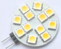 Then we might choose to use a commercial DC-to-DC converter like this one:  And the circuit arrangement might be like this:  This circuit works really well. The current fed to the DC-DC step-up converter is controlled by the voltage at point “A” combined with the resistance of the Joule Thief circuit as the transistor is operating in “emitter-follower” mode. Consequently, the voltage supplied to the Joule Thief circuit will be about 0.7 volts lower than at point “A”. The strategy for this lighting system is to provide lighting during the hours of darkness when the user is not asleep, and then when the light is turned off and the user is sleeping, the battery gets recharged. Living at the latitude of Ireland, the longest that I use lighting is seven hours in mid winter and far, far less in summer. A study carried out in Africa where there is no electrical service at all, states that the people there require lighting for 4 hours at night and 2 hours in the morning, so, with say, seven hours of lighting, that leaves 17 hours during which the battery can be recharged. As shown, the circuit draws about 70 milliamps of current when lighting two or more LED arrays brightly for seven hours when powered by one set of four AA-size Digimax 2285 maHr batteries. When the light is turned on, all of the lighting current is fed into the Joule Thief circuit and that allows it to charge a second set of four batteries. The very many extra hours during each day allows a very much greater period for recharging. While the circuit shows the off switch short-circuiting the lighting LEDs, there is nothing remotely like 70 milliamps of current draw and so the switch could drop the Joule Thief current down to just a few milliamps without lowering the charging rate. That would look like this:  The circuit shown so far has two sets of four batteries. It would be nice to swap them over every few minutes. Batteries which are powering a load don’t charge nearly as well as disconnected batteries which are being charged. However, the mechanism which switches between the two sets of batteries needs to have extremely low current draw in order not to waste current. One possibility for that would be to use a 5-volt latching relay like this one:  This is the electromechanical equivalent of a manual two-pole changeover switch. A brief pulse of current through the relay coil connected between the relay pins 1 and 16 locks the relay switch in one position while a brief pulse through the coil connected between pins 2 and 15 locks the switch in the other position. The current drain on the circuit would be almost zero. We could use a 555 timer chip to do the required switching. While a standard 555 chip can generally operate with a voltage as low as 4.5 volts, there are several more expensive 555 timers which are designed to work with much lower supply voltages. One of these is the TLC555 which has a supply voltage range from just 2 volts right up to 15 volts, which is a very impressive range. Another version is the ILC555N with a voltage range from 2 volts to 18 volts. Combining one of those chips with a latching relay produces a very simple circuit:  Joule Thief circuits do not need anything remotely like 70 milliamps of input current in order to charge a battery pack well. Consequently, we can use two or more Joule Thief circuits to share the current flowing through the lighting LED arrays. One addition which is helpful is a large capacitor “C” which supplies the circuit during the fraction of a second when the relay switches over:  or  The capacitors which pass a brief pulse to the relay depend on your particular relay but they are generally around 100 microfarads and 16-Volt working capacity. Here is a possible physical layout for a three Joule Thief circuit version. It uses a 125 mm x 35 mm piece of stripboard, that is, a piece which has 14 horizontal copper strips and each strip has 49 holes in it. Why that odd size? Because a piece that size was available as an offcut when the prototype was being built. The prototype layout is like this:  The red dots in the suggested physical layout indicate places where the copper strip on the underside of the board is broken. Patrick Kelly http://www.free-energy-info.com http://www.free-energy-devices.com http://www.free-energy-info.tuks.nl |