|
There is nothing magic about free-energy and by “free-energy” I mean something which produces output energy without the need for using a fuel which you have to buy. The device called the “Joe Cell” used to be one of the most difficult devices for any experimenter to get operating properly but new design data has changed all that. It is a passive device for concentrating energy drawn from the local environment and it takes great perseverance and patience to use one to power a vehicle. Here is some practical information on the Joe Cell. In 1992 in Australia, Graham Coe, Peter Stevens and Joe Nobel developed previously patented units which are now known by the generic name of the “Joe Cell”. Peter introduced Joe to Graham and they rehashed the patented cells which Graham knew about, using materials from the Local Dairy Production Facility NORCO. A two hour long video showing the Joe Cell was produced by Peter and Joe and the unit shown operating in the video was attached to Peter’s Mitsubishi Van. Joe had his equipment stolen and his dog killed, so he decided to keep a low profile, moving out into the wilds and not generating much publicity, in spite of fronting the two hour video recording. First, you need to understand that, at this point in time, building and using a Joe Cell of any variety, is as much an art as a science. It might best be explained by saying that creating building plans for it is rather like producing plans for painting a copy of the famous Mona Lisa painting. The instructions for the painting might be: 1. Buy a canvas, if one is not available, then here is how to make one. 2. Buy some oil-based paints, if none are available, then here is how you make them 3. Buy an artists brush, palette and charcoal, if none are available then this is how you make them. 4. Here is how you paint the picture. Even given the most complete and detailed instructions, many people, including myself, are unlikely to produce a top-quality copy of the Mona Lisa. It is not that the instructions are lacking in any way, it is the skill and ability of the person attempting the task which are not up to the job. It used to be that not everybody who built a Joe Cell had instant success. However, recent advances have changed all that. A Joe Cell is capable of powering a vehicle engine without needing to use conventional fossil fuel. So, what does the engine run on? I suggest that it runs on an energy field not yet spoken of by mainstream science. It is not unusual for newcomers to the subject to get confused by the Cell itself. The Cell consists of a metal container with tubes inside it. The container has what looks like ordinary water in it and it sometimes has a DC voltage applied across it. This causes many people to immediately jump to the false conclusion that it is an electrolyser. It isn’t. The Joe Cell does not convert water to hydrogen and oxygen gasses to be combined in the engine. The water in a Joe Cell does not get used up no matter how far the vehicle travels. It is possible to run a car on the gasses produced by electrolysis of water, but the Joe Cell has absolutely nothing whatsoever to do with electrolysis. The Joe Cell acts as a concentrator for our universal energy field. At the present time, there are at least fifteen different people who have built Joe Cells and managed to power vehicles using them. Several of these people use their Joe Cell-powered vehicles on a daily basis. Most of these are in Australia. The first Joe Cell-powered vehicle was driven some 2,000 kilometers across Australia. In broad outline, a Joe Cell is a 316L-grade stainless steel container, with a central cylindrical electrode, surrounded by a series of progressively larger stainless steel cylinders, and filled with water. This arrangement of steel shells and water focuses the energy field used to power the vehicle. The Cell itself is made up with the battery negative taken to the central electrode. The connection to this stainless steel electrode is made at the bottom with the electrical connection passing through the base of the cell container. This obviously needs careful construction to prevent any leakage of the conditioned water or the energy focused by the Cell. Surrounding the central electrode are two or three cylinders made of either solid or mesh stainless steel. These cylinders are not connected electrically and are held in position by insulating material which needs to be selected carefully as the insulation is not just electrical insulation but is also energy-field insulation. The outside stainless steel cylinder forms the container for the cell:   The picture above shows the general construction of a cell of this type although, unlike the description below, this one does not have the lip which is used for attaching the lid. It is included here just as a general illustration of how the cylinders are positioned relative to each other. A length of aluminium tubing typically three quarters of an inch (20 mm) in diameter will be needed for connecting the Cell to the engine, and a short length of strong, clear plastic pipe for the actual final connection to the engine, needed to prevent an electrical short-circuit between the Cell and the engine. This plastic pipe needs to be a tight push-fit as clamping clips are not used. A stainless steel compression fitting to fit the pipe is needed to make the seal between it and the lid of the Cell. It is very important that this fitting is stainless steel as other materials such as brass will prevent the cell from operating. The wrong material for this fitting has been the reason for many Cells not operating. Neither brass nor any other material (other than stainless steel) should not be used anywhere in the construction, whether it be for nuts, bolts, fittings, metal connections, or anything else. Ideally, natural rubber with no additives or colouring, failing that “Buna-n” (nitrile rubber) o-ring, or teflon, is needed for inter-cylinder bracing and some sheet to make the circular lid gasket. Also some white marine-grade Sikaflex 291 bedding compound. Natural rubber with no colouring or additives is the best insulator and should be used if at all possible. After extended use, Bill Williams of America has found that teflon spacers work better than the rubber and so he has switched to teflon. Don’t polish the tubes and never, ever use sandpaper or wet-and-dry paper on any of the components as the result is scored surfaces and each score reduces the effectiveness of the Cell. The Joe Cell looks like a very simple steel construction which could easily be made by any amateur. While it can be constructed by an amateur, it is not a simple construction as it is important to keep any acquired magnetic properties to a minimum. Consequently, it is suggested that an angle grinder is not used for any of the metalwork, and hand tools used for cutting and shaping. Also, if the cutting tool has previously been used to cut anything other than stainless steel it should not be used, or at the very least, thoroughly cleaned before use as contamination of your Cell components through particles of another material is critical and can prevent the Cell from working. It should be stressed again that the materials used in the construction of a Cell are absolutely critical if success is to be assured. If you have an experienced friend who has made many Cells work, then you can experiment with different materials, but if this is your first Cell and you are working on your own, then use the exact materials shown here and don’t end up with a Cell which doesn’t work. Recent Joe Cell Developments. One of the greatest problems with using a Joe Cell has been to get it operational. The reason for this has probably been due to the lack of understanding of the background theory of operation. This lack is being addressed at this time and a more advanced understanding of the device is being developed. These design dimensions cause ordinary tap water to go immediately to the fully functional “Stage 3” and remain in that state indefinitely, so, the only way of stopping the Cell is to physically take it apart. While it is still rather early to draw hard and fast conclusions, a number of results indicate that there are three separate, unrelated dimensions which are of major importance in constructing a properly “tuned” Joe Cell. It needs to be stressed that these measurements are very precise and construction needs to be very accurate indeed, with one sixteenth of an inch (1 mm) making a major difference. The dimensions are specified to this degree of accuracy as they represent the tuning of the Cell to the frequency of the energy which is being focussed by the Cell. The fact that there are three separate dimensions, suggests to me that there are probably three components of the energy field, or possibly, three separate energy fields. These three dimensions have been assigned names and are as follows: Golden dimension: 1.89745” (48.195 mm) Blue dimension: 3.458” (87.833 mm) Diamagnetic dimension: 0.515625" (13.097 mm) It is suggested that a Joe Cell should be constructed with cylinder heights which are a multiple of the ‘Golden’ length. Also, the water height inside the container should be below the tops of the inner cylinders and be a multiple of the basic length chosen for construction. The inner cylinders should be positioned the ‘Diamagnetic’ dimension above the base of the Cell. They should also be constructed from stainless steel of thickness 0.06445" (1.637 mm, which is very close to 1/16") and there should be a horizontal “Diamagnetic” gap between all of the vertical surfaces. The inner cylinders should be constructed from stainless steel sheet which is tack welded at the top and bottom of the seam, and all of the seams should be exactly aligned. The lid should be conical and sloped at an angle of 57O, with it’s inner surface matching the inner surface of the housing and the inner surface of the outlet pipe. The outer casing should not have any dome-headed fasteners used in its construction. The length of the outlet pipe should be made of aluminium and should be 15.1796" (385 mm) for ‘Golden’ height cylinders. That is 8H for Golden and should there be a need for a longer pipe, then those lengths should be doubled or tripled as the single dimensions no longer apply (this being a fractal effect). At this point in time, these are only suggestions as the science has not yet been firmly established. One possible arrangement is shown here:  It is not necessary for there to be four inner cylinders so an alternative might be:  A suggested Joe Cell design is shown below. This diagram shows a cross-section through a Joe Cell with four inner concentric stainless steel tubes. These tubes are positioned 0.515625 inches (13.097 mm) above the bottom of the Cell and the gap between each of the tubes (including the outer casing) is exactly that same ‘Diamagnetic’ resonant distance. It should be clearly understood that a Joe Cell has the effect of concentrating one or more energy fields of the local environment. At this point in time we know very little about the exact structure of the local environment, the fields involved and the effects of concentrating these fields. Please be aware that a Joe Cell which is properly constructed, has a definite mental / emotional effect on people near it. If the dimensions are correct and the construction accurate, then the effect on nearby humans is beneficial.  It should be pointed out that Joe Cells will be constructed with the materials which are readily to hand and not necessarily those with the optimum dimensions. If picking stainless steel sheet which is not the suggested optimum thickness, then a thinner, rather than a thicker sheet should be chosen. In case the method of calculating the diameters and circumferences of the inner cylinders is not already clear, this is how it is done: For the purposes of this example, and not because these figures have any particular significance, let’s say that the steel sheet is 0.06” thick and the outer cylinder happens to be 4.95” in diameter and it is 0.085” thick. People wanting to work in metric units can adjust the numbers accordingly where 1” = 25.4 mm.  Then, the inner diameter of the outside cylinder will be its outer diameter of 4.95”, less the wall thickness of that cylinder (0.08”) on each side which works out to be 4.79”. As we want there to be a gap of 0.516” (in practical terms as we will not be able to work to an accuracy greater than that), then the outside diameter of the largest of the inner cylinders will be twice that amount smaller, which is 3.758” :  And, since the material of the inner cylinder is 0.06” thick, then the inner diameter of that cylinder will be 0.12” less as that thickness occurs at both sides of the cylinder, which works out to be 3.838” :  The length of stainless steel needed to form that cylinder will be the circumference of the outer diameter of 3.758” which will be 3.758” x 3.1415926535 = 11.806 inches. The dimensions of the other inner cylinders are worked out in exactly the same way, bearing in mind that every steel thickness is 0.06”. The results for three inner cylinders would then be:  The first step is to construct the base plate, used to form the bottom of the container. Cut the largest diameter pipe to its correct length. (If you have difficulty in marking the cutting line, try wrapping a piece of paper around it, keeping the paper flat against the tube and making sure that the straight edge of the paper aligns exactly along the overlap, then mark along the edge of the paper). Place the pipe on a sheet of umwp (chopping board) plastic and mark around the bottom of the pipe. Cut the plastic to form a circular plate which sits flush with the bottom of the tube:  The next step is to mount the innermost pipe rigidly to the base plate. The pipe mounting needs to be exactly in the centre of the plate and exactly at right angles to it. This is probably where the most accurate work needs to be done. To complicate matters, the mounting needs to be connected electrically outside the base, be fully insulated from the base plate, and make a completely watertight fit with the base plate. For that reason, the arrangement looks a little complicated. Start by drilling a three quarter inch (18 mm) hole in the centre of the base plate. Construct and fit two insulating washers so that a half-inch stainless steel bolt will fit through the base plate while being securely insulated from it. The washers are made from Ultra-High Molecular Weight Polyethylene (plastic food-chopping boards are usually made from this material):  The washers which fit into the hole in the base plate need to be slightly less than half the thickness of the plate so that they do not actually touch when clamped tightly against the base plate, as shown in the lower part of the diagram. Cut another washer, using the full thickness of the plastic sheet. This will act as a spacer. Next, the plinth for the central cylinder needs to be made. This is the only complicated component in the construction. It is possible to make this component yourself. The local university or technical college will often be willing to allow you to use their lathe and their staff will usually do the job for you or help you to do it yourself. Failing that, your local metal fabrication shop will certainly be able to do it for you. If all else fails and this equipment is just not available, then a 3D printer may have to be used. A large piece of 316L stainless steel needs to be machined to produce the plinth shown below. The actual central cylinder needs to be a tight push-fit on the top of this component. To facilitate assembly, the central boss is given a slight chamfer which helps alignment when the tube is forced down on top of it. Peter Stevens recommends that tack welds (in stainless steel using a TIG welder) are used to connect the plinth to the outside of the cylinder. Three evenly-spaced vent holes are drilled in the plinth to allow the liquid inside the Cell to circulate freely inside the central cylinder.  An alternative method of construction which does not call for such a large amount of machining is to machine the plinth to take a standard stainless steel bolt as shown here:   When assembled, the arrangement should look like this:  This arrangement looks more complicated than it really is. It is necessary to have a construction like this as we want to mount the innermost tube securely in a central vertical position, with the battery negative connected to the cylinder, by a connection which is fully insulated from the base plate and which forms a fully watertight seal with the base plate, and to raise the central cylinder above the base plate. However, as the plastic washers would be affected by the heat when the base plate is joined to the outermost pipe, when all of the components shown have been prepared, they are taken apart so that the base plate can be fuse-welded to the outside tube. Unless you have the equipment for this, get your local steel fabrication workshop to do it for you. Be sure that you explain that it is not to be TIG welded, but fuse-welded and that the joint has to be fully watertight. At the same time, get them to fuse-weld a half-inch wide lip flush with the top edge of the tube. You cut this piece as a 6-inch (150 mm) circle with a 5-inch (125 mm) circular cut-out in the centre of it. When it is welded, it should look like this:  Cut a six-inch (150 mm) diameter lid out of 1/8 inch (3 mm) stainless steel. Cut a matching ring gasket of natural rubber (Buna-n material if natural rubber can’t be obtained), place it on top of the flange with the lid on top of it and clamp the lid firmly down on the flange. Drill a hole to take a 1/4 inch (6 mm) stainless steel bolt, through the lid and the middle of the flange. Insert a bolt and tighten its nut to further clamp the lid in place. An alternative to this for the more experienced metalworker, is to drill a hole slightly smaller than the bolt, and when all holes have been drilled, remove the lid, enlarge the lid holes to allow free passage of the bolts, and cut a thread inside the flange holes which matches the thread on the bolts to be used. This gives a very neat, nut-free result, but it calls for a greater skill level and more tools. If using nuts and bolts, drill a similar hole 180 degrees away and fasten a bolt through it. Repeat the process for the 90 degree and 270 degree points. This gives a lid which is held in place at its quarter points. You can now complete the job with either four more evenly-spaced bolts or eight more evenly-spaced bolts. The complete bolting for the twelve-bolt choice will look something like this when the cell is installed:  The lid can be finished off by drilling its centre to take the fitting for the aluminium pipe which will feed the output from the cell to the engine. This fitting, in common with every other fitting must be made of stainless steel. Video here. The next step is to assemble the neutral pipes. These pipes are held in place by the natural rubber insulators. These pieces are not placed lengthwise:  Place similar insulators at the other end of the pipes, directly above the ones already in place. If you look down the length of the tubes, then only three of the six insulators should be seen if they are correctly aligned. The spacers will be more effective if the ends are given a thin layer of the Sikaflex 291 bedding compound before the ends get compressed against the cylinder walls. Do the same for the next pipe, pushing tightly squeezed natural rubber insulators strips between the inner and outer pipes. Place them directly outside the insulators between the previous pipes so that when viewed from the end, it looks as if the rubber forms a single strip running through the middle pipe:  Carefully clean the surface of the base plate of the outer casing around the central hole, both inside and outside. Under no circumstances use sandpaper or wet-and-dry paper, here or anywhere else, as these abrade and score the surface of the steel and have a major negative effect on the operation of the Cell. Carefully lower the outer casing on to the assembly so that the threaded shaft goes through the central hole and the shaped washer fits tightly into the hole in the base of the outer housing. Apply a thin layer of the bonding compound to the face of the second shaped washer, place it over the shaft of the bolt and press it firmly into place to completely seal the hole in the base plate. Add a stainless steel washer and bolt and tighten the bolt to lock the assembly together. If using a bolt, a long-reach box spanner may be needed inside the central pipe for tightening the locking bolt. If one is not available, use a longer bolt through the washers, screw a second nut up on to the shank of the bolt, file two flats on the end of the bolt, clamp them in a vice to hold the bolt securely and tighten the locking nut. When the spare nut is unscrewed, it pushes any damaged fragments of the bolt thread back into place. Finish the assembly by adding three further rubber insulators between the top of the outermost pipes. Use a thin layer of Sikaflex 291 bonding compound on the cut faces of the insulators as this improves the insulation. Line the new insulators up with the insulators already in place and make them a tight fit. These extra insulators support the end of the tube assembly and reduce the stress on the plinth fitting at the base of the central tube when the unit is subjected to knocks and vibration when the vehicle is in motion.  The construction of the basic unit is now complete, with the exception of the lid fitting for the aluminium pipe which feeds the engine. The construction so far has been straightforward engineering with little complication, but if you do not feel confident about this construction, then advice and help can be got from the experienced members at the Yahoo Group here or alternatively, the companion Group here. Bill Williams in America found that when he fitted a Joe Cell to his Ford pickup, the performance suddenly became like a Formula One racing car and very gentle use of the throttle was needed. He says: "Over the summer, I used the truck to haul firewood for this winter's wood supply. I added 5 gallons of fuel to bring the fuel level to the half tank mark. I ran the truck with the cell which I installed a month earlier. Basically, I tried to forget about the cell being installed in the truck. The Ignition timing was set at about 25 degrees before TDC with no vacuum connect to the distributor. The fuel line was still connected so "shandy" mode was being used. The surprising thing is that the truck did not use any fuel during the two and a half months of driving in the woods. In fact, when I parked the truck at the end of the wooding season, I physically sounded the fuel tank (it is a 'behind the seat' tank). It was still showing the half full mark. I pulled the cell for the winter and have it sitting on the bench waiting for spring to arrive for it to be installed again. I don't even pretend to understand this technology, but I keep hoping that someone will come up with a viable explanation of how the cell works". When installing the Joe Cell in a vehicle, the first step is to insulate the Cell from the engine components. This insulation is not just electrical insulation which is easily accomplished, but it is a case of introducing sufficient separation between the Cell and the engine to stop the concentrated (invisible) energy leaking away instead of being fed to the engine through the aluminium tube. So, wrap the Cell walls in three layers of double-laminated hessian sacking (“burlap”), pulling it tightly around the outer tube. Tie (a minimum of) three wooden dowels along the length of the Cell and bend the mounting bracket around the dowels. The purpose of this is solely to ensure that there is at least a three quarter inch air gap between the walls of the Cell and everything else, including the mounting bracket:  The mounting details depend on the layout of the engine compartment. The really essential requirement is that the aluminium pipe running to the engine must be kept at least 4 inches (100 mm) away from the engine electrics, radiator, water hoses and air-conditioning components. The last four inches or so, of the tube going to the engine cannot be aluminium as that would cause an electrical short-circuit between the (occasional) positive outer connection to the outside of the Cell and the engine itself which is connected to the battery negative. To avoid this, the final section of the pipe is made using a short length of clear plastic piping, forming a tight push-fit on the outside of the aluminium tube and on the connection to the intake of the engine’s carburettor. There should be a 3/4 inch (18 mm) gap between the end of the aluminium pipe and the nearest metal part of the carburettor. If it is just not possible to get an airtight fit on the intake to the carburettor and a hosepipe clamp has to be used, be sure that the fitting is non-magnetic stainless steel. If such a fitting cannot be found, then improvise one yourself, using only 316L grade stainless steel.  In the installation shown above, you will notice that the aluminium tube has been run well clear of the engine components. A vacuum gauge has been added but this is not necessary. For the early stages of installation, the aluminium pipe runs to the vacuum port of the carburettor but stops about 3/4 inch (20 mm) short of it, inside the plastic tubing. This method of connection is advisable for the initial setting up of the vehicle modification. At a later date, when the engine has been running with the Cell and is attuned to it, the Cell operates better if the pipe is connected to one of the bolt heads on the engine block, again using the plastic tube and a gap between the aluminium tube and the bolt head. Some people feel that a safety pressure -release valve with a safe venting arrangement should be used if the pipe feeding the engine, terminates on a bolt head. If it is still available, this video shows Bill Williams operating his Joe Cell. Notes: Engines running while powered by a Joe Cell act in a somewhat different manner. They can idle at a very low number of revs per minute, the power available on acceleration is much greater than normal and they appear to be able to rev very much higher than ever before without any difficulty or harm. The type of Cell described in this document was built by Bill Williams in the USA with the help and assistance of Peter Stevens of Australia. Bill describes his first driving experience with his 1975 F 250, 360 cu. in. (5.9 litre) Ford pickup: Well, all I can say is "who needs an Indy car when you can drive an old FORD" – WOW!!!! The first five miles after leaving home were wild. I had to be extremely careful on how I pressed the accelerator. I gingerly crept up to 45 mph and that was with moving the pedal maybe half and inch. The throttle response was very crisp or touchy. With about a 1/8" of movement the next thing I new I was close to 80 mph. If I lifted off ever so slightly on the throttle, it felt like I was putting the brakes on and the speed would drop down to 30 mph or so. "Very erratic". If I barely even touched or bumped the pedal it felt like I had pushed a nitrous oxide booster button. WOW !!! As stated earlier, the first 5 miles were wild and things started to change. The engine started to buck or surge with very large rpm changes and literally threw me against my seat belt. It got so bad I just took my foot completely off the pedal and rode the brakes to stop the truck. The truck left skid marks on the pavement every time the engine surged in rpm. Well anyway, I manage to get it stopped and shut it off with the ignition key - thank GOD ! I retarded the timing, turned the gasoline back on, crossed my fingers and hit the ignition key, and the engine took right off, revving to maybe 4,000 rpm and then gradually decreased to 700 rpm. I took a deep breath and put it into drive and the truck responded close to normal again. I made it into work a little late, but late is better than never the way I see it. After working during the day at the job and thinking what I could do to stop this erratic rpm oscillation, I decided to disable the cell and drive home on gas. WOW !!! Peter Stevens states that the main reason for the erratic behaviour of the Cell was due to outside air leaking into the Cell, and he stresses that Cells need to be completely airtight. It is also clear that the timing was not set in the correct position. All properly built Cells give enhanced engine power. Comments from an expert in July 2012: We are into an entirely different approach now, one which entails introducing specific vibrations into the cell. An optimum implementation involves cutting each tube to a specific length so as to make it self-exciting, but that’s not necessary because the frequencies can be introduced just using a caliper, or a precise length of metal touched against the tubes in a sequence. Since this approach was totally different from traditional Joe Cell work, we set up a discussion group specifically for it: http://tech.groups.yahoo.com/group/vibrational_combustion_technology/ The nice thing about this approach is that it’s ultra stable. Once the vibration is set up the only way to stop it is to take the cell apart. This construction method totally eliminates the human influence factor problem! In fact, a cell can affect the engine even without there being water in the cell. Another nice thing about it is the mathematical design process is implemented in a couple of spreadsheets. My thinking at this time, is that we now need to incorporate specific engine parameters into the design to tune the cell to a particular engine. We have been a bit sidetracked lately and have been working a lot on the healing aspects of Torsion fields: http://groups.yahoo.com/group/awaken_to_vibration/ but I hope to get back into engine testing soon. Advances in 2011. In an effort to develop a device to emulate the function of a Joe cell without it’s inherent stability issues, Dave Lowrance came up with the idea of a set of 3 concentrically-wound torsion field coils. In early testing it has become apparent that a field is being generated, as demonstrated by their effect on two test engines, even with no power being applied to the coils. This is the very early stage of the investigation so this initial design is being released with the hope that others will wind and test similar coils and report their results to the appropriate groups, so that we can learn more about them through further experimenting on a variety of different engines. The initial set of coils were wound on 7/8” (22 mm) diameter stainless steel tubing which happened to be to hand. The use of stainless steel is not significant and two successful replications have used half-inch (12 mm) PVC plastic pipe, as using a non-ferrous material is the main requirement. The wire diameter has an effect and while 20 gauge (0.812 mm diameter) enamelled copper wire was used for the coils shown here, coils wound with 12 gauge (2.05 mm diameter) copper wire work much better and it is now thought that the weight of copper in the winding is important. For the first layer, a length of 311 cm is used and wound on the former in a clockwise direction. The ends of the wire are secured with tape, leaving three or four centimeters of wire exposed at each end of the coil, for connection purposes. This is the first layer wound and secured: 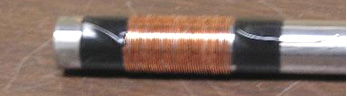 The wire for the second layer is cut to a length of 396 centimeters. This second coil layer will be longer than the first layer, so before winding it, it’s necessary to build up the area at both ends of the first layer with tape:  This is so that the second layer of wire will have the same diameter along it’s entire length. It is probably a good idea to completely cover the first layer of wire with tape to ensure good electrical insulation.  The second wire layer is also wound in a clockwise direction: 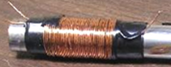 The wire for the third layer is cut to a length of 313 centimeters. Since it will be covering less length along the former, there is no need to build up the ends of the earlier layers. So, simply cover the second winding with tape, and then wind on the third layer, but this time, the coil is wound in a counter-clockwise direction and then the entire coil is covered in tape to protect it. 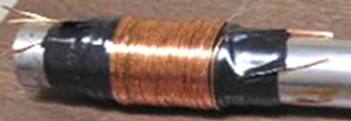 To be sure that the second and third layers are centred over the earlier layers, it is a good idea to locate the centre of the wire and start winding from the middle outwards in both directions:  It has been found that one end of the centre winding is similar to the centre tube of the Joe cell, and the opposite end of the outer winding functions like the canister of a Joe cell. In theory, this can be tested by connecting a small capacitor between these two points, and checking for a low DC voltage using a digital voltmeter. Like a Joe cell, polarity is really the important issue to test for, since we do want the positive polarity end to transfer the energy, and the negative polarity end to be connected to engine ground. If the polarity is wrong, simply use the opposite ends of both coils. In the testing the negative end was connected to chassis ground, and the positive end to a Hull-effect type oil probe already installed in each test vehicle. The oil probe is Robert Hull's contribution to this technology. He found that if you apply a torsion field to the oil, it will charge up an engine in a way similar to a Joe cell, but more consistently than a Joe cell would. There are two basic types of Hull-effect probe - the simplest is just a wire inserted down the dipstick tube. However, the preferred method is to remove the oil-pressure sensor and insert a T-fitting, then slide an insulated stainless steel rod into the high-pressure oil at that point. By using an oil probe, one can eliminate the aluminium transfer tube in favour of a length of wire. The experimenter who wound the 20-gauge coils then wound a larger diameter set using 12-gauge wire on a 1.5-inch (38 mm) diameter former. He fitted these over the original set and connected just two wires, one end of the innermost of the six coils and the opposite end of the outermost coil. This gave about a 25% reduction in the fuel used by an old Honda Accord car with an Electronic Fuel Injection system. Fuel-less operation has not yet been achieved, but that could just be a matter of getting the engine set up properly. Some of the issues we need to deal with are things like antifreeze, which destroys the dielectric properties of water, and inhibits it from charging up. This has never been discussed, but it is one of the key things which limited the ability of people to succeed with their cells. Oil is a similar issue. Some oils, particularly the ones with all the additives and detergents, simply won't charge up. There still needs to be a lot of testing done. For instance, with this setup it might be better to connect one end of each coil to ground. Or possibly the coils would do better if the windings were all connected in series. This is all uncharted territory! Dave’s original concept was to use a set of these coils to replace each tube of a Joe cell. The engine from an old Pinto car is also being used as a test bed. Attempts were made to run it completely fuel-less. It would kick repeatedly, but just wasn't quite there. It would only kick at a very specific timing setting - somewhere between 50-60 degrees before Top Dead Centre. The Pinto has antifreeze and with just water it's more likely to run fuel-less. But that should be a last-resort option, since most people do need antifreeze. Devices such as the Joe cell tend to work really well on engines which have a carburettor because the spark timing can be adjusted quite easily. They work well on older EFI engines (probably those prior to OBD2) but they can be a real problem on the newer EFI models as they are liable to cause a fuel injection error state to be reached almost immediately. The newer ECUs control everything so tightly that they are almost impossible to work with (which was probably a design objective of the ECU design). The Pinto engine had not been started for over six months. No T-field devices were connected to the engine during this period, so we can assume that there was little or no residual charge on the engine. The cooling system had only water in it. The crankcase was filled with NAPA brand 30-weight oil. We fiddled with the engine to get it started. At that time the car had a little motorcycle carburettor on it, rather than the stock carburettor and the timing was set quite a bit advanced. After just a few minutes of idling we realised that the engine was getting extremely hot with the exhaust manifold glowing red. So we shut it down. Being the optimist that I am, we went ahead and connected the coils at this time. The next morning I took a little compass and found that it didn’t point to North anywhere within about 2 feet of the car body - a very good sign! So we went ahead and started it up, and carefully monitored the head temperature with an infra-red thermometer. The temperature rose slowly to about 170 degrees F which is a little below normal. After verifying that the temperature held steady at that value, I tested with the compass again, and now it was messed up out to about 10 feet from the body. So the field strength had jumped up about 500% after starting the engine. We then played with the carburettor and timing to get the smoothest operation at the lowest RPM at which it would idle smoothly. The RPM appeared to be well below a normal idle RPM., and when I went back and checked the timing, it was very close to 60 degrees before Top Dead Centre. At this point everything was looking so good that we tried a few attempts at fuel-less operation, but the engine died each time. Due to pressure of other work, the car was ignored for a couple of months. When I finally got back to doing a little further testing, I found it surprisingly easy to get it started again. I didn't have to reset the timing to get it running. It actually started up with little effort, which was amazing, since the timing was still way advanced. It should be nearly impossible to start an engine with the timing set like that. The spark is just occurring at the wrong time in the cycle so it should try to push the pistons in the wrong direction. Anyhow, it was starting to get cold here, so I decided to install some antifreeze, and that just set everything way back. It reduced the field strength by over 80%. Since then Dave has come up with a coil-set designed to charge up antifreeze, but I was disappointed when I tried it. It did better with the antifreeze than the original set did, but we came to the conclusion that the antifreeze destroys water’s diamagnetic properties to the point that the mixture is just hard to charge up. Working on this problem is the reason why I didn't release the coil info sooner. I kept hoping that we might solve this problem as well, but we didn't. However, this just might not be as big a problem as I thought, because I've heard that well-charged water just might have a significantly lower freezing point. This has not been tested yet to verify it. An interesting side issue is the fact that the water which I drained out when adding antifreeze, showed no sign of rust. It was perfectly clear. Under normal circumstances, with no additives in the cooling system, this water should have been a horrible orange mess. It wasn't, and that has to be because of the field on the engine. The Pinto is not roadworthy, so I have no way of knowing what kind of fuel consumption is possible with this setup or what power it might be capable of producing. At this time, I just use it to test different devices, and to try for fuel-less operation. However, if I was to achieve a consistent, repeatable fuel-less operation, it could become roadworthy very quickly, so I could do some actual road testing. Patrick Kelly http://www.free-energy-info.com http://www.free-energy-info.tuks.nl |