|
There is nothing magic about free-energy and by “free-energy” I mean something which produces output energy without the need for using a fuel which you have to buy. Free energy devices have been around for a very long time now. I have stood beside a water mill and it’s power is scary as it could crush you in moments and never even notice. That mill is on a quietly flowing small river and it can operate at any time day or night without having to pay anything for the power which it uses. It will have cost quite a bit to build the mill in the first place, but after that, it produces major power year after year. Most free-energy devices are just like that as it costs to build them in the first place, but after that they run for free. This presentation is mainly for people who have never come across free-energy and know nothing about it. So, each chapter deals with just one device and tries to explain it clearly. There is nothing magical about free energy. I consider that a “free-energy” device is one which outputs energy without the need for having to buy fuel to power the device. We live in a vast energy field and there are many different ways to access that energy and make it into a form which is useful to us – typically electricity. One of those ways is to pass current through a coil of wire and then suddenly which of the current. When you do that, the coil produces a sudden, very large voltage spike which causes energy to flow into the coil from the outside environment. For this inflow of energy to be useful, we need it to happen many times per second, and that required an electronic circuit. Electronic circuits are not difficult to understand, nor are they hard to construct, and I will explain as we go along. Mr. Z. Kaparnik, in the "Ingenuity Unlimited" section of the November 1999 edition of the magazine "Everyday Practical Electronics" showed his clever design which he called the “Joule Thief”. His circuit allows a discharged 1.5-volt dry battery to power a 3-volt LED (“Light Emitting Diode”). His circuit is very simple and very clever and has become enormously popular. This is his circuit: 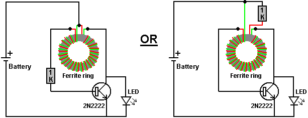 The battery looks like this: 
The 1K resistor looks like this: 
The 2N2222 transistor looks like this: 
The LED looks like this: 
The Ferrite ring looks like this: 
The circuit is very simple: 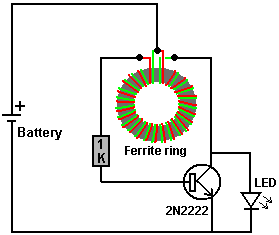
Two short lengths of thin wire (enamelled solid copper wire) are used to wind a few turns around the toroid. This makes two separate coils wound side by side. When the battery is connected, current flows through the red coil, is limited by the 1000 ohm resistor and flows through the transistor back to the battery. This turns the transistor on which drives a pulse of current through the green coil, and that causes a corresponding pulse in the red coil. That process repeats itself, perhaps 200,000 times per second. Because of the characteristics of any coil, the voltage produced in the green coil when the transistor switches off is very much higher than the voltage of the battery, and well in excess of the 3-volts needed to light the LED. If the battery is only half a volt (and unable to run the original TV remote or whatever) it can still light the 3-volt LED. So, a tiny torch with just one LED as the light source can be powered by a battery which was considered “dead”. This is interesting and instructional. You connect the battery and the LED lights up. You disconnect the battery and the LED goes out. This looks as if the battery is lighting the LED, but in fact, it isn’t. What is actually happening is that the battery powers the circuit, causing the green coil to produce high voltage spikes, and those spikes cause energy to flow into the circuit from outside, lighting the LED (which the battery just can’t do). This very simple circuit is causing the environment to supply free power to you and that is very impressive! The circuit can be constructed using an ordinary strip of screw blocks. However, we can use that incoming energy for other things. For example, we could use it to recharge a rechargeable battery: 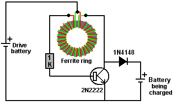 In this arrangement the LED is replaced by an ordinary diode (almost any diode will do) and the incoming power fed into a rechargeable battery. I have used this circuit to recharge a 2285 milliamp-hour AA size battery from 0.6 volts to 1.41 volts in one hour without running the drive battery down by any significant amount. A 1N4148 diode looks like this: 
However, the big gains are when two or more batteries are charged at the same time: 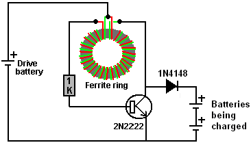 Two NiMh rechargeable batteries have less voltage than a 3-volt LED, so obviously, if the circuit can light a 3V LED it can definitely recharge two NiMh batteries. 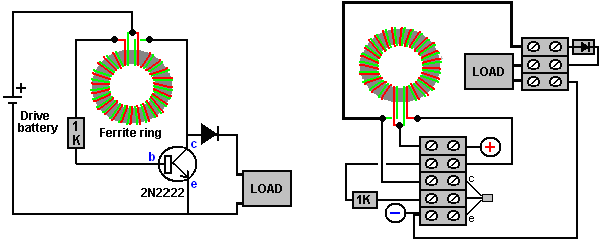 The transistor connections are like this: 
Mr Kaparnik used a tiny ferrite ring out of an old Mains LED light bulb, but it is not necessary to have a ring at all. I have used a cylinder of paper instead and it works very well. The coil can be wound quite easily. A pencil makes a good former for a coil, so cut a strip of paper 150 millimeters wide and wrap it around the pencil to form a paper cylinder several layers thick and 150 millimeters wide and seal it with Selotape:  Make sure that when you pull the paper cylinder together with the Selotape, that you don’t stick the paper to the pencil as we will want to slide the completed cylinder off the pencil after we wind the coil on it. The coil can now be wound on the paper cylinder, and for this, it is convenient to use two fifty gram reels of enamelled copper wire. The wire which I used is 0.375 millimeters in diameter. There are many different ways to wind a coil. The method I use is to leave at least 150mm of spare wire at the beginning so that the coil can be connected when wound, then make three or four turns like this:  Then hold those turns in place with Selotape before winding the rest of the coil. Finally, the right hand end of the coil is secured with Selotape and then both ends are covered with electrical tape as Selotape deteriorates with time. While this coil has been wound with only one layer, if you want, an extra single covering of paper can be used to cover the first layer and a second layer wound on top of it before being taped and slid off the pencil. While the diagrams above show the strands of wire in two colours, the reality is that both wires will be the same colour and so you end up with a coil which has two identical looking wires coming out of each end. You make the wires at each end more than the length of the coil so that you have enough connecting wire to make the final connections. Use a multimeter (or battery and LED) to identify a wire at each end which connects all the way through the coil and then connect one end of that wire to the other wire at the other end. That makes the central tap of the coil “B”: 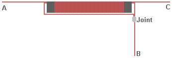 The coil needs to be checked carefully before use. Ideally, the joint is soldered and if the enamelled copper wire used is the “solderable” type (which is the most common type) then the soldering iron heat will burn the enamel away after a few seconds, making a good joint on what used to be fully enamelled wires. A resistance test needs to be carried out to check the quality of the coil. First, check the DC resistance between points “A” and “B”. The result should be less than 2 ohms. Then check the resistance between points “B” and “C” and that should be an exactly matching resistance value. Finally, check the resistance between points “A” and “C” and that value will be more than the “A” to “B” resistance but never seems to be twice. If it isn’t more, then the joint is not properly made and needs to be heated up with the soldering iron and possibly more solder used on it and the resistance measurements made again. The simple circuit as shown can charge four AA batteries in series when the circuit is driven by just one AA battery. 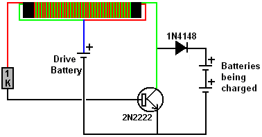 I have used a 1N4148 diode which is a silicon diode with a voltage drop across it of 0.65 or 0.7 volts and it has worked well. However, a germanium diode with its much lower 0.25 to 0.3 voltage drop is generally recommended, perhaps a 1N34A diode. It is also suggested that using two or three diodes in parallel is helpful. This simple Joule Thief circuit can be used with a little ingenuity, to power the lamps of chapter 1 without the need for a solar panel, but that is for a later chapter. There are various circuits which I have shown which use the well-known “Joule Thief” circuit as part of the design. These devices have worked well for me. However, in 2014, Sucahyo stated that some people found that pulse-charging batteries for a few times, caused those batteries to then have “surface charge” where the battery voltage rose without there being a corresponding genuine charge inside the battery. That is something which I have never experienced myself but that might be because I didn’t discharge and recharge batteries a sufficient number of times for me to experience the effect. My preferred form of Joule thief uses a bi-filar coil of 0.335 mm diameter wire wound on a paper cylinder formed around a pencil and only 100 mm (4 inches) long, as that produces a very cheap and lightweight circuit. As I understand it, the Joule Thief produces a rapid stream of high voltage spikes of very short duration. Those spikes cause the local environment to feed static energy into both the circuit and the circuit’s load device (typically an LED or a battery). While I have never experienced surface charge from a Joule Thief circuit, I tested some old Digimax 2850 mAHr test batteries which had been sitting unused for more than a year. These did indeed show a surface charge effect when load tested. The first test used one battery to drive the circuit and charged three batteries in series using this circuit: 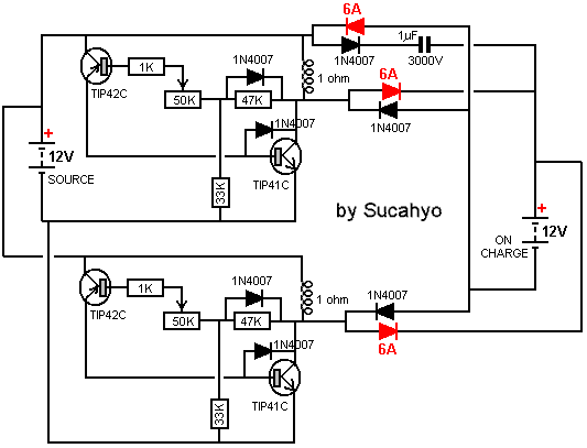 which looks rather complicated with two of the transistors connected upside down and protection diodes connected between transistor collector and base. Sucahyo says that he has used this circuit for four years now without experiencing any surface charge effects. My preferred form of Joule thief uses a bi-filar coil of 0.335 mm diameter wire wound on a paper cylinder formed around a pencil and only 100 mm (4 inches) long, as that produces a very cheap and lightweight circuit. As I understand it, the Joule Thief produces a rapid stream of high voltage spikes of very short duration. Those spikes cause the local environment to feed static energy into both the circuit and the circuit’s load device (typically an LED or a battery). While I have never experienced surface charge from a Joule Thief circuit, I tested some old Digimax 2850 mAHr test batteries which had been sitting unused for more than a year. These did indeed show a surface charge effect when load tested. The first test used one battery to drive the circuit and charged three batteries in series using this circuit: 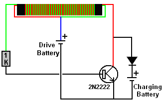 But no matter how long the circuit operated, it would not charge the output battery above 4.0 volts which is 1.33 volts per battery. The load test results were terrible with the voltages at one hourly intervals being 3.93V, 3.89V, 3.84V, 3.82V and 3.79V after only five hours of powering the load. That is ridiculous performance as those batteries managed 22 hours of load powering with the solar panel design. Perhaps the batteries were damaged. So I overcharged them with a main operated charger, reaching 4.26 volts which is 1.42 volts per battery and the hourly load testing results were 4.21, 4.18, 4.16, 4.15, 4.13, 4.12, 4.10, 4.08, 4.07, 4.07, 4.06, 4.05, 4.03, 4.03, 4.02, 4.01, 4.00 (after 17 hours), 3.99, 3.99, 3.98, 3.97, 3.97, 3.96, 3.96, 3.95 after 25 hours and 3.90 after 33 hours. Clearly, there is nothing wrong with the batteries so the effect must be a factor of the charging. Feeding static electricity into a capacitor converts it into normal “hot” electricity, but we want a very simple circuit, so the next step was to add in a 100 volt 1 microfarad capacitor which looks like this:  making the circuit: 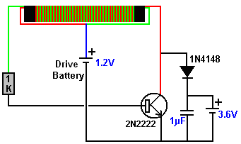 With the battery on charge removed, the voltage on the capacitor reaches 22 volts. Charging the same batteries with this circuit reached 4.14 volts and produced load results of 4.09, 4.05, 4.01, 3.98, 3.96, 3.93, 3.90, 3.88, 3.85, 3.83, 3.81 and 3.79 volts after 12 hours which is much better than the 5-hour total previously experienced. However, obviously, something better is needed. The next step is to use a diode bridge of 1N4148 diodes instead of the single diode, giving this circuit: 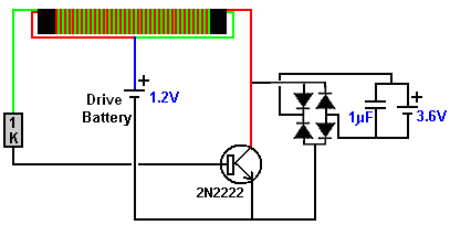 Without the charging battery connected, this circuit gives 28 volts on the capacitor and the battery charging is good, giving load testing results of 4.18, 4.16, 4.15, 4.13, 4.11, 4.10, 4.08, 4.08, 4.06, 4.05, 4.04, 4.03, 4.02, 4.00, 3.99, 3.98, 3.97, 3.96, 3.95, 3.95, 3.94, 3.94, 3.93, 3.93, and 3.93 volts after powering the load for 24 hours. This seems to be a very satisfactory result for such a minor alteration. If two 1.2V batteries are used to drive the circuit, without a battery on charge, then the voltage on the capacitor reaches 67 volts, but that is not necessary for charging a 12-volt battery. Although the change is slight, the circuit operation is changed considerably. The capacitor does not discharge instantly and so, for some of the time between the sharp Joule Thief pulses, the capacitor supplies extra charging current to the battery on charge. This does not mean that the battery being charged is charged much faster and you can expect that full charging will take several hours. I have not yet tested it, but I would expect that by using two or more of these circuits simultaneously, should increase the rate of charge;  There is no need to restrict the battery on charge to a nominal 3.6 volts in any of these circuits as a single 1.2 volt drive battery can easily charge a 4.8 volt battery or larger. The value of the capacitor has a considerable effect and I suggest a one microfarad capacitor is a good choice. It has been argued that the two additional diodes on each side of the battery being charged are not necessary, although I have shown them to isolate the two circuits from each other. Patrick Kelly http://www.free-energy-info.com |