|
There is nothing magic about free-energy and by “free-energy” I mean something which produces output energy without the need for using a fuel which you have to buy. In 2012 a contributor who uses the ID ‘Wonju-Bajac’ started a forum to investigate the work of Clemente Figuera here and member ‘hanlon1492’ contributed enormously by producing English translations of Figuera’s patents. Clemente Figuera of the Canary Islands died in 1908. He was a highly respected individual, an Engineer and University Professor. He was granted several patents and was known to Nikola Tesla. Figuera’s design is very simple in outline. In 1902 the Daily Mail announced that Mr. Figuera, a Forestry Engineer in the Canary Islands, and for many years Professor of Physics at St. Augustine’s College, Las Palmas, had invented a generator which required no fuel. Señor Figuera has constructed a rough apparatus by which, in spite of it’s small size and it’s defects, he obtains 550 volts, which he utilises in his own house for lighting purposes and for driving a 20 horse-power motor. The Figuera Device looks like a complicated transformer, but in fact, it isn’t. Instead, it is two sets of seven opposing electromagnets with an output coil positioned between each opposing pair of electromagnets. The physical position of the electromagnets and output coils is important as they are positioned very close to each other and there are induced magnetic fields between adjacent electromagnets and between the output coils due to their close proximity. The two sets of electromagnets are wound with very low-resistance, high-current wire or possibly, even with thick foil. The information given in the Figuera patent states that the electromagnets will be referred to in the patent by the letters “N” and “S” and it is now thought that those two letters are deliberately misleading as people tend to think of those letters referring to “North magnetic pole” and “South magnetic pole” while in reality, the electromagnets almost certainly oppose each other, that is, with North poles facing each other or possibly, with South poles facing each other. The arrangement is believed to be like this when seen from above: 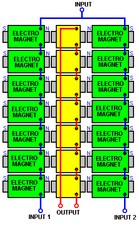 This arrangement creates a magnetic Bloch wall (or magnetically null point) in the centre of the yellow output coils and the position of that magnetic balance point is very easily moved if the power supply to the two sets of electromagnets is altered slightly and any movement of that magnetic balance point creates a substantial electrical output due to the alteration of the magnetic lines cutting the turns of wire in the yellow output coils. While the sketch shown above indicates a small gap between the electromagnets and the output coils, it is by no means certain that any such gap is needed and while winding the three coils is more convenient if they are separate, when wound and being assembled, their cores may well be pushed together to form one continuous magnetic path. Another thing which has confused people (including me), is the drawing in the patent which looks like an electrical commutator, but which is NOT part of the Figuera generator design. It looks like this: 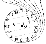 The dotted lines indicate internal electrical connections, so for example, contact 14 is connected to contact 3, but let me stress again that this unit is NOT part of the design and while it is used to “explain” the actual operation, I would not be surprised if it were not intended to misdirect people from the actual operation. This point has been stressed and it has been suggested that the actual working device is magnetic in nature and could be constructed like this: 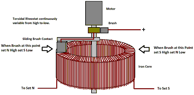 This looks like a very simple device but it is an item of major importance in the Figuera design. First, the core is solid iron (sometimes called “soft iron” but if you were beaten with a bar of it you certainly wouldn’t call it “soft”). The most important characteristic of such a core is its magnetic properties as it is able to store energy. Please remember that this switching device is primarily magnetic in nature. It looks like this: 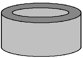 This core is then wound with thick wire – perhaps AWG #10 or 12 SWG (2.3 x 2.3 mm square wire) . The turns of wire should be tight, side by side and sit exactly flat on the top surface as the wire there will be contacted by the sliding brush: 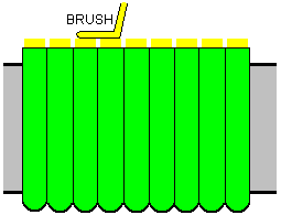 The sliding brass contact or “brush” is dimensioned so that it connects across two adjacent wires so that there is never any sparking as the brush contact slides around the circle of wires. The brush is driven by a small DC motor. In order for the sliding brush to contact the wire, the plastic insulation needs to be removed from the top half of the wire with the remaining insulation keeping the turns from short-circuiting together. The wire is wound half of the way around the iron core and a short length of wire is left to make an electrical connection. An additional winding is then made to cover the remaining half of the core and again, a length for connection is left before cutting the wire. This gives you two windings each covering 180 degrees around the core. The wire turns are strapped tightly with tape or cord wound around the side of the core as that holds the wires securely in place. The two wire ends on each side are connected together, giving a 360 degree winding with good electrical connections 180 degrees apart. There are many ways to arrange the small DC motor so that it drives the brush slider. The motor could be mounted on a strip passing over the core, or on the baseboard, or to one side using a belt or gearwheel drive link. It does not matter which direction the brush moves around the core. The speed of rotation is not critical either although it does determine the alternating frequency of the output. In most cases, the output will power a heating element or will be converted to DC to give the local mains frequency and voltage. When we first look at a device like this, we immediately think of the flow of electric current passing through the wire wound around the iron core. It appears as if the current is limited by the overall length of the wire between the brush position and the two outputs, but the reality is that while that is correct to a certain extent, the main control of the current flow is the magnetic field inside the circular iron core, and that field causes reluctance (resistance to current flow) proportional to the number of coil turns between the brush and each output. This alters the current flow to the set of “N” electromagnets compared to the current flow to the set of “S” electromagnets. As the magnetic intensity generated by the set of “N” electromagnets increases, the magnetic intensity generated by the set of “S” electromagnets decreases. But, as the magnetic power of the set of “N” electromagnets overcomes the magnetic field of the set of “S” electromagnets, that magnetic field gets pushed back into the soft iron core of the commutator device, essentially storing energy in that core. When the system needs to replace the energy lost in heating, it can use that stored magnetic energy in the commutator core, raising the overall efficiency. In this design, the current flowing through the electromagnets is always in the same direction and never drops to zero, merely oscillating in its intensity. The overall arrangement is like this: 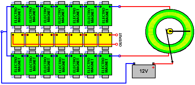 While the sketch above shows a 12-volt battery, there is no great reason why it should not be 24-volt or higher, especially if the wire used to wind the electromagnets is smaller diameter. The amount of power needed to create a magnetic field is not related to strength of the magnetic field and a larger number of turns of thinner wire with a small current flowing through the wire can create a stronger magnetic field than few turns of thick wire with a large current flowing through those turns, however the effects of those different coils is quite marked. Patrick Kelly http://www.free-energy-info.co.uk http://www.free-energy-info.tuks.nl |