|
There is nothing magic about free-energy and by “free-energy” I mean something which produces output energy without the need for using a fuel which you have to buy. Converting water into gas is useful as the gas produced can be used as a fuel. In its most simple form, two metal plates are placed in water and an electric current is passed between the plates. This causes the water to break down into a mixture of hydrogen gas and oxygen gas (The two components used in the Space Shuttle). The greater the flow of current, the larger the volume of gas which will be produced. The arrangement is like this:  Remembering that the result of doing this is to produce fuel for the Space Shuttle, you should avoid doing this indoors and letting the gas produced by the process collect on the ceiling. There are many videos on the web where people act in a dangerous manner and perform electrolysis indoors using a container which is open at the top as shown above. Please, please don't do that as it is highly dangerous - it is not a party popper which pushes the Space Shuttle into space! If you were to collect a cupful of HHO gas and light it, the resulting ignition would probably damage your hearing permanently, so don't do it under any circumstances. Just like the fact that a very useful chain saw is a dangerous device which needs to be treated with respect, so too, please understand that the very useful HHO gas mix contains a lot of energy and so needs to be treated with respect. This style of electrolysis of water was investigated by the very talented and meticulous experimenter Michael Faraday. He presented his results in a very technical and scientific format which are not understood by most ordinary people. But in simple terms, he tells us that the amount of HHO gas produced is proportional to the current flowing through the water, so to increase the rate of gas production, you need to increase the current flow. Also, he found that the working voltage between the two "electrode" plates is 1.24 volts. This sounds a bit technical, but it is a highly useful piece of information. In the arrangement shown above, twelve volts is being connected across two plates in water. Faraday tells us that only 1.24 volts of that twelve volts will go to make HHO gas and the remaining 10.76 volts will act as an electric kettle and just heat the water, eventually producing steam. As we want to make HHO gas and not steam, this is bad news for us. What it does tell us is that if you choose to do it that way, then only 10% of the power taken by the booster actually makes HHO gas and a massive 90% is wasted as heat. We really don't want a low electrical efficiency like that. One way around the problem is to use two cells like this:  This arrangement uses our 1.24 volts twice while the twelve volts stays unchanged and so the electrical efficiency goes up to 20% and the heat loss drops to 80%. That is quite an improvement but even more important is the fact that twice as much HHO gas is now produced, so we have doubled the electrical efficiency and doubled the gas output, giving a result which is four times better than before. We could go one step further and use three cells like this:  This time we are using three of our 1.24 volt sections and this gives us an electrical efficiency of 30% and three times the amount of gas, making the system nine times more effective.  This is definitely going in the right direction, so how far can we take it when using a twelve volt battery? When we use the construction materials which years of testing has shown to be particularly effective, there is a small voltage drop across the metal plates, which means that the very best voltage for each cell is about 2 volts and so with a twelve volt battery, six cells is about the best combination, and that gives us an electrical efficiency of 62% and six times as much gas, which is 37 times better than using a single cell, and the wasted electrical power drops down from 90% to 38%, which is about as good as we can get. Of course, it would not be practical to have six boxes each as large as a car battery as we would never manage to fit them into most vehicles. Perhaps we could just put all the plates inside a single box. Unfortunately, if we do that, a good deal of the electric current would flow around the plates and not make much gas at all. A top view of this arrangement is shown here:  This is a disaster for us as now we will not get your six times the gas production or our massively reduced heating. Thankfully, there is a very simple fix for this problem, and that is to divide the box up into six watertight compartments using thin partitions like this:  This gives us back our high efficiency by blocking the current flow past the plates and forcing the current to flow through the plates, producing gas between every pair of plates. In passing, if this booster were to be powered by the electrics of a vehicle, then the voltage although called "twelve volts" will actually be almost fourteen volts when the engine is running so that the "twelve volt" battery will get charged. This would allow us to use seven cells inside our electrolyser, rather than the six cells shown above and that would give us seven times the gas volume that a single pair of plates would give. Some people prefer six cells, and others, seven cells - the choice is up to the person constructing the unit. We have been discussing the methods of increasing the gas production and reducing the wasted energy, but please don't assume that the objective is to make large volumes of HHO gas. It has been found that with many vehicle engines, very good performance gains can be had with a HHO gas production rate of less than 1 litre per minute ("lpm") added to the air entering the engine. Flow rates of as little as 0.5 to 0.7 lpm are frequently very effective. Remember, the HHO gas from a booster is being used as an igniter for the regular fuel used by the engine and not as an additional fuel. The big advantage of an efficient booster design is that you can produce the wanted volume of gas using a much lower current, and so there will be a lesser extra load on the engine. Admittedly, there is not much additional engine load needed by a booster, but we should reduce the extra amount by intelligent design. In the discussion above, the battery has been shown connected directly across the booster or "electrolyser". This should never be done as there is no protection against a short-circuit caused by a loose wire or whatever. There should be a fuse or a circuit-breaker as the first thing connected to the battery. Circuit breakers are available from any electrician's supply outlet as they are used in the "fuse box" in homes, to provide protection for each lighting circuit and each power socket circuit. They are not expensive as they are manufactured in very large volumes. They are also available on eBay. The circuit breaker is wired like this:  a common design (rated at 32 amps) looks like this: 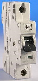 Some would-be constructors feel that some aspects of the construction are too difficult for them. Here are some suggestions which might make construction more straightforward. Constructing a seven-cell housing is not difficult. Pieces are cut out for two sides, one base, one lid and six absolutely identical partitions. These partitions must be exactly the same so that there is no tendency for leaks to develop. If you decide to use the bent-plate system of electrodes shown on the next few pages, then drill the bolt holes in the partitions before assembling them:  The bottom piece is the same length as the sides, and it is the width of the partitions plus twice the thickness of the material being used to build the housing. If acrylic plastic is being used for the construction, then the supplier can also provide an “adhesive” which effectively “welds” the pieces together making the different pieces appear to have been made from a single piece. The case would be assembled like this:  Here, the partitions are fixed in place one at a time, and finally, the second side is attached and will mate exactly as the partitions and ends are all exactly the same width. A simple construction for the lid is to glue and screw a strip all the way around the top of the unit and have the lid overlap the sides as shown here:  A gasket, perhaps of flexible PVC, placed between the sides and the lid would assist in making a good seal when the lid is bolted down. The gas outlet pipe is located in the centre of the lid which is a position which is not affected if the unit is tilted when the vehicle is on a steep hill. Years of testing have shown that a really good choice of material for the electrode plates is 316-L grade stainless steel. However, it is very difficult to connect those plates electrically inside the cells as you need to use stainless steel wire to make the connections and bolted connections are really not suitable. That leaves welding the wires to the plates and welding stainless steel is not something which a beginner can do properly as it is much more difficult than welding mild steel. There is a good alternative, and that is to arrange the plate material so that no wire connections are needed:  While this six-cell design may look a little complicated to a quick glance, it is really a very simple construction. Each of the plates used in the central cells is just this shape:  The plate shapes shown above are arranged so that there is access to the bolts from above and they can be reached by a spanner and held steady while the other nut is being tightened. Unless you are skilled in bending plates, I suggest that you use stainless steel mesh for the plates. It works very well, can be readily cut using tin snips or any similar tool and it can be bent into shape by the home constructor using simple tools - a vice, a piece of angle iron, a small piece of mild steel sheet, a hammer, etc. You will find a skip outside any metal fabrication shop where scrap pieces are tossed for recycling. There will be off-cuts of various sizes of angle iron and all sorts of other small sections of sheet and strip. They are in the skip mainly to get rid of them as the fabrication business gets paid almost nothing for them. You can use some of these pieces to shape your booster plates, and if you feel bad about costing the business about a penny, then by all means put them back in the skip afterwards. If you clamp your plate between two angle irons in a vice, then careful, repeated gently tapping with a hammer close to the bend location, will produce a very clean and neat bend in the plate:  The bent sheet can then be clamped between two steel strips and a sharp U-shaped bend produced by tapping with a hammer, again, along the line of the required bend:  The thickness of the steel bar on the inside of the bend has to be the exact width of the required gap between the finished plate faces. This is not particularly difficult to arrange as 3 mm, 3.5 mm, 4 mm, 5 mm and 6 mm are common thicknesses used in steel fabrication, and they can be combined to give almost any required gap. There are many varieties of stainless steel mesh. The style and thickness are not at all critical but you need to choose a type which is reasonably stiff and which will hold its shape well after it is bent. This style might be a good choice: 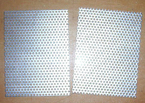 Your local steel supplier probably has some types on hand and can let you see how flexible a particular variety is. The shape shown above is for a "three plate per cell" design where there are two active plate faces. Ideally, you want two to four square inches of plate area per amp of current flowing through the cell, because that gives very long electrode life and minimum heating due to the plates. This style of construction is reasonably easy to assemble as the two bolts which pass through the partitions and which hold the plates rigidly in place, can be accessed from above, two spanners being used to lock them tight. Lock nuts are optional. If you feel that your particular mesh might be a little too flexible or if you think that the bolts might eventually loosen, then you can attach two, or more, separator insulating pieces - plastic washers, plastic bolts, cable ties or whatever to one of the plate faces. These will hold the plates apart even if they were to become loose. They also help to maintain the gap between the plates. This gap has to be a compromise because the closer the plates are together, the better the gas production but the more difficult it is for the bubbles to break away from the plates and float to the surface and if they don't do that, then they block off some of the plate area and prevent further gas production from that part of the plate as the electrolyte no longer touches the plate there. A popular choice of gap is 1/8 inch which is 3 mm as that is a good compromise spacing. Circular spacers would look like this:  If the current is low enough, an even more simple shape which has just a single pair of active plate surfaces per cell, can be used as shown here:  Any of these designs can be 6-cell or 7-cell and the plates can be constructed without outside help. You will notice that the electrical connections at each end of the booster are submerged to make sure that a loose connection can't cause a spark and ignite the HHO gas in the top of the housing. There should be a gasket washer on the inside to prevent any leakage of the electrolyte past the clamping bolt. If you want to use three active plate pairs in each cell, then the plate shape could be like this:  The electrolyte is a mix of water and an additive to allows more current to flow through the liquid. Most of the substances which people think of to use to make an electrolyte are most unsuitable, producing dangerous gasses, damaging the surfaces of the plates and giving uneven electrolysis and currents which are difficult to control. These include salt, battery acid and baking soda and I strongly recommend that you do not use any of these. What is needed is a substance which does not get used up during electrolysis and which does not damage the plates even after years of use. There are two very suitable substances for this: sodium hydroxide, also called "lye" or "caustic soda". In the USA, this is available in Lowes stores, being sold as "Roebic ‘Heavy Duty’ Crystal Drain Opener". The chemical formula for it is NaOH. One other substance which is even better is potassium hydroxide or "caustic potash" (chemical formula KOH) which can be got from soap-making supply shops found on the web. Both NaOH and KOH are very caustic materials and they need to be handled with considerable care.  Bob Boyce of the USA is one of the most experienced people in the construction and use of boosters of different designs. He has kindly shared the following information on how to stay safe when mixing and using these chemicals. He says: These materials are highly caustic and so they need to be handled carefully and kept away from contact with skin, and even more importantly, eyes. If any splashes come in contact with you, it is very important indeed that the affected area be rinsed off immediately with large amounts of running water and if necessary, the use of vinegar which is acidic and so will neutralise the caustic liquid. When making up a solution, you add small amounts of the hydroxide to distilled water held in a container. The container must not be glass as most glass is not high enough quality to be a suitable material in which to mix the electrolyte. The hydroxide itself should always be stored in a sturdy, air-tight container which is clearly labelled "DANGER! - Potassium (or Sodium) Hydroxide". Keep the container in a safe place, where it can’t be reached by children, pets or people who won't take any notice of the label. If your supply of hydroxide is delivered in a strong plastic bag, then once you open the bag, you should transfer all of its contents to sturdy, air-tight, plastic storage containers, which you can open and close without any risk of spilling the contents. Hardware stores sell large plastic buckets with air tight lids that can be used for this purpose. When working with dry hydroxide flakes or granules, wear safety goggles, rubber gloves, a long sleeved shirt, socks and long trousers. Also, don’t wear your favourite clothes when handling hydroxide solution as it is not the best thing to get on clothes. It is also no harm to wear a face mask which covers your mouth and nose. If you are mixing solid hydroxide with water, always add the hydroxide to the water, and not the other way round, and use a plastic container for the mixing, preferably one which has twice the capacity of the finished mixture. The mixing should be done in a well-ventilated area which is not draughty as air currents can blow the dry hydroxide around. When mixing the electrolyte, never use warm water. The water should be cool because the chemical reaction between the water and the hydroxide generates a good deal of heat. If possible, place the mixing container in a larger container filled with cold water, as that will help to keep the temperature down, and if your mixture should “boil over” it will contain the spillage. Add only a small amount of hydroxide at a time, stirring continuously, and if you stop stirring for any reason, put the lids back on all containers. If, in spite of all precautions, you get some hydroxide solution on your skin, wash it off with plenty of cold running water and apply some vinegar to the skin. Vinegar is acidic, and will help balance out the alkalinity of the hydroxide. You can use lemon juice if you don't have vinegar to hand - but it is always a good idea to have a bottle of vinegar handy. The concentration of the electrolyte is a very important factor. Generally speaking, the more concentrated the electrolyte, the greater the current and the larger the volume of HHO gas produced. However, there are three major factors to consider: 1. The resistance to current flow through the metal electrode plates. 2. The resistance to current flow between the metal plates and the electrolyte. 3. The resistance to current flow through the electrolyte itself. 1. In a good electrolyser design like those shown above, the design itself is about as good as a DC booster can get, but understanding each of these areas of power loss is important for the best possible performance. We were taught in school that metals conduct electricity, but what was probably not mentioned was the fact that some metals such as stainless steel are quite poor conductors of electricity and that is why electrical cables are made with copper wires and not steel wires. This is how the current flow occurs with our electrolyser plates:  The fact that we have folds and bends in our plates has no significant effect on the current flow. Resistance to current flow through the metal electrode plates is something which can’t be overcome easily and economically, and so has to be accepted as an overhead. Generally speaking, the heating from this source is low and not a matter of major concern, but we provide a large amount of plate area to reduce this component of power loss as much as is practical. 2. Resistance to flow between the electrode and the electrolyte is an entirely different matter, and major improvements can be made in this area. After extensive testing, Bob Boyce discovered that a very considerable improvement can be made if a catalytic layer is developed on the active plate surface. Details of how this can be done are given later in the companion "D9.pdf" document as part of the description of Bob’s electrolyser.  3. Resistance to flow through the electrolyte itself can be minimised by using the best catalyst at its optimum concentration. When using sodium hydroxide, the optimum concentration is 20% by weight. As 1 cc of water weighs one gram, one litre of water weighs one kilogram. But, if 20% (200 grams) of this kilogram is to be made up of sodium hydroxide, then the remaining water can only weigh 800 grams and so will be only 800 cc in volume. So, to make up a 20% "by weight" mix of sodium hydroxide and distilled water, the 200 grams of sodium hydroxide are added (very slowly and carefully, as explained above by Bob) to just 800 cc of cool distilled water and the volume of electrolyte produced will be about 800 cc. When potassium hydroxide is being used, the optimum concentration is 28% by weight and so, 280 grams of potassium hydroxide are added (very slowly and carefully, as explained above by Bob) to just 720 cc of cold distilled water. Both of these electrolytes have a freezing point well below that of water and this can be a very useful feature for people who live in places which have very cold winters. Another factor which affects current flow through the electrolyte is the distance which the current has to flow through the electrolyte - the greater the distance, the greater the resistance. Reducing the gap between the plates to a minimum improves the efficiency. However, practical factors come into play here as bubbles need sufficient space to escape between the plates, and a good working compromise is a spacing of 3 mm. which is one eighth of an inch.  However, there is a problem with using the optimum concentration of electrolyte and that is the current flow caused by the greatly improved electrolyte is likely to be far more than we want. To deal with this we can use an electronic circuit called a "Pulse-Width Modulator" (or “PWM”) circuit. These are often sold as "DC Motor-Speed Controllers" and if you buy one, then pick one which can handle 30 amps of current. A PWM circuit operates in a very simple way. It switches the current to the electrolyser On and Off many times every second. The current is controlled by how long (in any one second) the current is On, compared to how long it is Off. For example, if the On time is twice as long as the Off time (66%), then the average current flow will be much greater than if the On time were only half as long as the Off time (33%). When using a PWM controller, it is normal to place its control knob on or near the dashboard and to mount a simple low-cost ammeter beside it so that the driver can raise or lower the current flow as is considered necessary. The arrangement is like this:  There is a more sophisticated circuit controller called a "Constant-current Circuit" and that allows you to select the current you want and the circuit then holds the current at your set value at all times. However, this type of circuit is not readily available for sale although some outlets are preparing to offer them. Some of the most simple boosters don't use a PWM circuit because they control the current flow through the booster by making the concentration of the electrolyte very low so that the resistance to current flow through the electrolyte chokes off the current and holds it down to the desired level. This, of course, is far less efficient and the resistance in the electrolyte causes heating, which in turn, is an operational problem which needs careful handling by the user. The advantage is that the system appears to be more simple. There is a difference in the gas produced by a DC Motor-speed Controller pulsed current. The gas quality is higher and the bubbles form between the plates rather than on the plates:  Feeding HHO gas to any engine is highly beneficial as in addition to improving the miles per gallon of the engine, harmful emissions are massively reduced and any old carbon deposits inside the engine get cleaned away over time, giving a smoother and more powerful engine performance. No matter which variety of electrolyser cell is used, it is essential to put a bubbler between it and the engine air intake if the gas is to be fed to the engine. This is to prevent any accidental ignition of the gas reaching the electrolysis cell. Also, no electrolyser should be operated or tested indoors. This is because the gas is lighter than air so any leak of gas will cause the gas to collect on the ceiling where it can ignite if triggered by the slightest spark (such as is generated when a light switch is turned on or off). Hydrogen gas escapes very easily indeed as its atoms are very, very small and can get through any tiny crack and even directly through many apparently solid materials. Testing electrolysers should be done outdoors or at the very least, in very well-ventilated locations. Using at least one bubbler is an absolutely vital safety measure. A typical bubbler looks like this:  Bubbler construction is very simple indeed. It can be any size or shape provided that the outlet of the entry tube has at least five inches (125 mm) of water above it. Plastic is a common choice for the material and fittings are easy to find. It is very important that good sealed joints are made where all pipes and wires enter any container which has HHO gas in it. This, of course, includes the bubbler. It is also a good idea to drill additional holes in the entry pipe from half way down below the surface of the water, in order to create a larger number of smaller bubbles The anti-slosh filling or a baffle plate in the cap is to prevent the water in the bubbler from splashing up into the exit pipe and being drawn into the engine. Various materials have been used for the filling including stainless steel wool and plastic pot scourers. The material needs to prevent, or at least minimise, any water passing through it, while at the same time allowing the gas to flow freely through it. Caution: An electrolyser is not a toy. If you make and use one of these, you do so entirely at your own risk. Neither the designer of the electrolyser, the author of this document or the provider of the internet display are in any way liable should you suffer any loss or damage through your own actions. While it is believed to be entirely safe to make and use an electrolyser, provided that the safety instructions are followed, it is stressed that the responsibility is yours and yours alone. An electrolyser feeding gas to an engine should not be considered as an isolated device. You need to remember that both electrical and gas safety devices are an essential part of any such installation. The electrical safety devices are a circuit-breaker (as used by any electrician when wiring a house) to protect against accidental short-circuits, and a relay to make sure that the booster does not operate when the engine is not running. A fairly typical arrangement is like this:  Patrick Kelly http://www.free-energy-info.com http://www.free-energy-info.tuks.nl |