|
There is nothing magic about free-energy and by “free-energy” I mean something which produces output energy without the need for using a fuel which you have to buy. Free energy devices have been around for a very long time now. I have stood beside a water mill and it’s power is scary as it could crush you in moments and never even notice. That mill is on a quietly flowing small river and it can operate at any time day or night without having to pay anything for the power which it uses. It will have cost quite a bit to build the mill in the first place, but after that, it produces major power year after year. Most free-energy devices are just like that as it costs to build them in the first place, but after that they run for free. This presentation is mainly for people who have never come across free-energy and know nothing about it. So, each chapter deals with just one device and tries to explain it clearly. The late Robert Adams, an electrical engineer of New Zealand designed and built several varieties of electric motor using permanent magnets on the rotor and pulsed electromagnets on the frame of the motor (called the "stator" because it does not move). He found that if they were configured correctly, then the output from his motors exceeded their input power by a large margin (800%).  The diagram of his motor intended to show the basic operating principle is shown here:  If a motor is built like this, then it will most certainly work but it will never reach 100% efficiency let alone exceeding the 100% mark. It is only with a specific configuration which is hardly ever publicised that high performance figures can be achieved. While Robert has shown several different configurations, in order to avoid confusion I will describe and explain just one of them. I am indebted to several of Robert's friends and colleagues for the following information and I should like to express my thanks to them for their help and support in bringing you this information. First and foremost, high performance can only be achieved with the clever use of power collection coils. These coils need to be positioned accurately and their power collection restricted to just a very short arc of operation by connecting them to, and disconnecting them from, the output circuit at just the right instant so that the back EMF generated when the current draw stops, actually contributes to the drive of the rotor, speeding it on it's way and raising the overall efficiency of the motor/generator as a whole. Next, the shape of the magnets used is important as the length to width proportion of the magnet alters the pattern of it's magnetic fields. In direct opposition to the diagram shown above, the magnets need to be much longer than their width (or in the case of cylindrical magnets, much longer than their diameter). Further, a good deal of experimentation has shown that the size and shape of the electromagnets and pick-up coils has a major influence on the performance. The cross-sectional area of the core of the pick-up coils should be four times that of the cross-sectional area of the permanent magnets in the rotor. The reverse is true for the cores of the drive coils as their cores should have a cross-sectional area of just one quarter of the rotor magnet cross-sectional area. Another point which is almost never mentioned is the fact that big circuit gains will not be achieved unless the drive voltage is high. The minimum should be 48 volts but the higher the voltage, the greater the energy gain, so voltages in the 120 volts (rectified US mains voltage) to 230 volts (rectified mains voltage elsewhere) should be considered. Neodymium magnets are not recommended for drive voltages under 120 volts. There are several important steps in the way that the Robert Adams motor/generator works and it is important for you to understand each of the steps. Step 1: A rotor magnet is attracted to the iron core of a stator “drive” electromagnet. As it approaches the drive electromagnet, the lines of magnetic force from the stator magnet move across the drive electromagnet coil. This generates an electric current in the drive electromagnet coil and that current is fed back to the battery which is powering the motor/generator:  Notice that the movement of the rotor is caused by the permanent magnets being attracted to the iron cores of the drive electromagnets and not by any electric current. The electric flow is going back into the battery and is being caused by the movement of the rotor which in turn is being caused by the permanent magnets. Step 2: When the rotor turns far enough, the magnets align exactly with the cores of the drive electromagnets. The rotor continues to rotate because of its inertia, but if we do nothing about it, the rotor magnet attraction to the drive electromagnet core will act to slow it down and then drag it back to the drive coil core. We want to prevent that, so we feed a small amount of current into the drive electromagnet coils – just enough current to stop the backward drag of the rotor magnets. This current is NOT to push the rotor magnets away, it is just enough to prevent the rotor being slowed down:  Step 3: When the rotor magnet has moved away far enough, the current being fed to the drive electromagnets is cut off. As happens with any coil, when the current is cut off a large reverse voltage spike is generated. That voltage spike is rectified and fed back to the battery. The system so far produces a spinning rotor for very little current draw from the battery. But we want the system to provide us with excess electrical output, so for that, four additional electromagnets are added around the rotor. These output coils are mounted on a non-magnetic disc which can be rotated to adjust the gap between the drive coils and the output coils. Like the rotor magnets, the output coils are spaced evenly around the circumference of the rotor at 90-degree intervals:  Step 4: Surprisingly, the output coils are switched Off for most of the time. This sounds mad but it most definitely isn’t mad. With the output coils disconnected, the approaching rotor magnets generate a voltage in the output coil windings but no current can flow. As no current is flowing, no magnetic field is generated and so the rotor magnets just pull directly towards the output coil iron cores. The maximum output coil voltage is when the rotor magnets are aligned with the output coil cores. At that instant the output switch is closed and a strong pulse of current is drawn off and then the switch is opened again, cutting off the output current. The output switch is closed for only three degrees or so of the rotor’s rotation and it is off again for the next eighty seven degrees, but the opening of the switch has a major effect. The switch being opened cuts off the current flowing in the output coils and that causes a major reverse voltage spike causing a major magnetic field which pushes the rotor on its way. That voltage spike is rectified and passed back to the battery. The rectification of every possible spare voltage pulse as described, returns 95% of the drive current to the battery, making this an extremely effective motor/generator. The performance can be further enhanced by rotating the set of output coils to find their optimum position and then locking the disc in place. When properly set up, this generator has an output current which is eight times greater than the input current. Notice that the cores of the "generator" pick-up coils are very much wider than the cores of the drive coils. Also notice the proportions of the magnets where the length is much greater than the width or diameter. The four generator windings are mounted on a single disc allowing them to be moved through an angle to find the optimum operating position before being locked in position and the two drive coils are mounted separately and held clear of the disc. Notice also that the power pick-up coils are much wider compared to their length than the drive coils are. This is a practical feature which is explained in greater detail later. The DC input is shown passing through Robert's custom-made contactor switch which is mounted directly on the shaft of the motor/generator. This is a mechanical switch which allows an adjustable On / Off ratio, which is known as the "Mark/Space Ratio" or, if the "On" period is of particular interest, the "Duty Cycle". Robert Adams indicates that when the motor is running and has been adjusted to it's optimum performance, then the Mark/Space ratio should be adjusted to minimise the On period and ideally get it down to about 25% so that for three quarters of the time, the input power is actually switched off. There are various ways of achieving this switching while still having a very sharp turn on and turn off of the power. Robert considered mechanical switching of the drive current to be a very good option although he was not opposed to using the contact to power a transistor to do the actual switching and so reduce the current through the mechanical contacts by a major factor. His reasons for his preference for mechanical switching are that it gives very sharp switching, needs no electrical power to make it operate and it allows current to flow in both directions. The current flow in two directions is important because Robert produced various ways of getting the motor to feed current back into the driving battery, allowing it to drive the motor for long periods without lowering its voltage hardly at all. His preferred method of switching is shown here:   This switching gear operates as follows: The timing disk is bolted securely to the drive shaft of the motor and its position is set so that the electrical switch-on occurs when the rotor magnet is exactly aligned with the drive coil core. Adjustment of that timing is done by loosening the locking nut, rotating the disc very slightly and clamping the disc in position again. A spring washer is used to keep the assembly tight when the device is running. The disc has a star-shaped piece of copper sheet set into its surface and two silver-tipped, copper arm "brushes" slide across the surface of the copper star. One of these two brushes is fixed in position and slides across the copper star near the drive shaft, making a permanent electrical connection to it. The second brush slides alternatively on the non-conducting surface of the disc and then over the conducting arm of the copper. The second brush is mounted so that its position can be adjusted and, because the copper arms taper, that alters the ratio of the "On" time to the "Off" time. The actual switching is achieved by current flowing through the first brush, through the copper arm and then through the second brush. The brush arms shown in the diagram above rely on the springiness of the copper arm to make a good brush-to-copper electrical connection. It might be preferred to use a rigid brush arm, pivot it and use a spring to ensure a very good contact between the brush and the copper star at all times. The adjustment of the On to Off time, or "Mark/Space Ratio" or "Duty Cycle" as the technical people describe it, could perhaps do with some description. If the moveable brush is positioned near the centre of the disc, then, because of the tapering of the copper arms, the part of the non-conducting disc that it slides over is shorter and the part of the conducting copper arm with which it connects is longer, as the two sliding paths are about the same length, the current is on for about the same length as it is off, giving a Mark/Space ratio of about 50% as shown here:  If, instead, the moveable brush is positioned near the outside edge of the disc, then because of the tapering of the copper arm, the On path is shorter and the non-conducting Off path is very much longer, being about three times as long as the On path, giving a Mark/Space ratio of about 25%. As the moveable brush can be positioned anywhere between these two extremes, the Mark/Space ratio can be set to any value from 25% to 50%.  The two brushes can be on the same side of the drive shaft or on opposite sides as shown. One important feature is that the brushes touch in a position where the disc surface is always moving directly away from the brush mounting, causing any drag to be directly along the arm and giving no sideways loading on the brush. The diameter of the device is usually one inch (25 mm) or less. You will also notice that the output is switched although the diagram does not give any indication of how or when that switching takes place. You will notice that the diagram has angles marked on it for the optimum positioning of the pick-up coils, well, an Adams Motor builder with a forum ID of "Maimariati" who achieved a Coefficient Of Performance of 1,223, found that the optimum switching for his motor is On at 42 degrees and Off at 44.7 degrees. That tiny 2.7 degree part of the rotor turn gives a substantial power output and cutting the output current off at that point causes the back EMF of the coils to give the rotor a substantial additional boost on its way. His input power is 27.6 watts and the output power is 33.78 kilowatts Now for some practical details. It is suggested that a good length for the power pick-up coils can be determined by using the “paper clip test” described by Ron Pugh of Canada. This is done by taking one of the permanent magnets used in the rotor, and measuring the distance at which that magnet just begins to lift one end of a 32 mm (1.25 inch) paper clip off the table. The optimum length of each coil from end to end is exactly the same as the distance at which the paper clip starts to lift.  The core material used in the electromagnets can be of various different types including advanced materials and alloys such as ‘Somalloy’ or 'Metglas'. The power pick-up coil proportions are important as an electromagnet becomes less and less effective as its length increases, and eventually, the part furthest from the active end can actually be a hindrance to the effective operation. A good coil shape is one which you would not expect, with the coil width being, perhaps 50% greater than the coil length: Contrary to what you would expect, the device draws in energy from the local environment better if the end of the pick-up coil farthest from the rotor is left unaffected by any other part of the device and the same applies to the magnet facing it. That is, the coil should have the rotor at one end and nothing at the other end, that is, no second rotor behind the coil. The speed at which the voltage is applied to, and removed from, the coils is very important. With very sharp voltage rises and falls, additional energy is drawn from the surrounding environmental energy field. If using transistor switching, then the IRF3205 FET has been found to be very good and a suitable driver for the FET is the MC34151. If using a Hall-effect semiconductor to synchronise the timing, say the UGN3503U which is very reliable, then the life of the Hall-effect device is much improved if it is provided with a 470 ohm resistor between it and the positive supply line, and a similar 470 ohm resistor between it and the negative line. These resistors in series with the Hall-effect device effectively “float” it and protect it from supply-line spikes".  Here, two electromagnets are driven by the battery via Robert's 4-arm commutator which is mounted on the rotor shaft. Some of the recommendations given by Robert are the opposite of what you would expect. For example, he says that a single rotor construction tends to be more electrically efficient than one where several rotors are mounted on a single shaft. Robert is against the use of reed switches and he recommends making one of his commutators. At one stage, Robert recommended the use of standard transformer shims for constructing the cores of the electromagnets. This has the advantage that matching bobbins for holding the coil windings are readily available and can still be used for pick-up coils. Later on, Robert swung towards the use of solid cores from the old PO Series 3000 telephone relays and eventually said that electromagnet cores should be solid iron.  The diagrams presented by Robert show the magnets located on the rim of the rotor and pointing outwards. If this is done, then it is essential that the magnets in the rotor are firmly attached on at least five of their six faces and the possibility of using a ring of non magnetic material such as duct tape around the outside should be considered. That style of construction also lends itself to streamlining the rotor by having a completely solid construction, although it might be remarked that the motor would run better and more quietly if it were enclosed in a box which had the air pumped out of it. If that is done, then there will be no air resistance and because sound can't pass through a vacuum, quieter operation is bound to result. While this may sound a bit complicated, there is no reason why it should be. All that is needed is two discs and one central disc which is the thickness of the magnets, with slots cut in it, the exact size of the magnets. The assembly starts with the lower disc, magnets and central disc. These are glued together, probably with epoxy resin, and that holds the magnets securely on four faces as shown here:  Here, the magnets are attached on the lower face, the right and left faces, and the unused pole face, and when the upper disc is attached, the upper faces are also secured and there is the minimum of air turbulence when the rotor spins:  There is a "sweet spot" for the positioning of the power pick-up coils and it will usually be found that this is two or three millimeters away from the rotor. If that is the case, then there will be room for an outer band of duct tape on the rim of the rotor to provide additional protection against the failure of the magnet attachment method. High-power versions of the motor/generator need to be enclosed in a metal box which is earthed as they are quite capable of generating a substantial amount of high frequency waves which can damage equipment such as oscilloscopes and create TV reception interference. There would probably be an improvement in performance as well as a reduction in sound if the box was airtight and had the air pumped out of it. If that is done, then there will be no air resistance as the rotor spins and since sound does not pass through a vacuum, quieter operation is possible. Experienced rotor builders do not like the radial magnets style of construction because of the stresses on the magnet attachments if high rotational speeds are reached. It should not need to be said, but it is obviously a major requirement to keep your hands well away from the rotor when the motor is running as it is perfectly possible to be injured by the high-speed movement if you are careless. Please remember that this presentation must not be considered to be a recommendation that you build or use any device of this nature and it must be stressed that this text, in common with the entire contents of this eBook, is intended to be for information purposes only and no representations or warranties are implied by this presentation. Should you decide to construct, test or use any device, then you do so entirely at your own risk and no liability attaches to anybody else if you sustain any kind of injury or property damage as a result of your own actions. Because of the mechanical stresses caused during rotation, some experienced constructors feel that the magnets should be embedded in the rotor as shown here where they are kept well clear of the rim of a rotor which is made from a tough material. This is so that the outer strip of the material prevents the magnets breaking loose and becoming dangerous high-speed projectiles, which at best would destroy the electromagnets and at worst could injure someone quite badly:  It needs to be remembered that the proportions of the magnets are for the magnet length to be more than the diameter, so in cases like this where circular magnet faces are to be used, the magnets will be cylindrical and the rotor needs to have a significant thickness, which will depend on the magnets which are available locally. The magnets should be a tight push-fit in their holes and securely glued in place. Robert Adams has used this construction style as well. However, if an arrangement like this is used, then there will be a substantial sideways pull on the rotor as it reaches the electromagnet core, tending to pull the magnets out of the rotor.  It is important that the rotor should be perfectly balanced and have the minimum amount of bearing friction possible. This calls for precision construction and either roller or ball bearings. The construction style shown above has the distinct advantage that it has an open end to both the magnet and the coils and this is believed to facilitate the inflow of environmental energy into the device. When getting ball-race bearings for an application like this, please be aware that "closed" bearings such as these are not suitable as supplied: 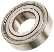 This is because this type of bearing is usually packed with dense grease which completely destroys its free motion, making it worse as a bearing than a simple hole-and-shaft arrangement. However, in spite of this, the closed or "sealed" bearing is popular as the magnets tend to attract dirt and dust and if the device is not enclosed in a steel box as is necessary for the high power versions, then having the seal is considered to be an advantage. The way to deal with the grease packing is to soak the bearing in an isopropyal solvent cleaner to remove the manufacturer's grease, and then, when it has dried out, lubricate the bearing with two drops of a high quality thin oil. If it is intended to house the motor/generator in an earthed, sealed steel box then an alternative type of bearing which might be suitable is an open design like this: 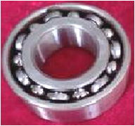 especially if the air is removed from the box. Some constructors prefer to use ceramic bearings which are supposed to be immune to dirt. One supplier is here but as with everything else, these choices have to be made by the builder and will be influenced by his opinions. To help with assessing the wire diameter and length which you could use, here is a table of some of the common sizes in both American Wire Gage and Standard Wire Gauge:  Robert Adams states that the DC resistance of the coil windings is an important factor. The overall resistance should be either 36 ohms or 72 ohms for a complete set of coils, whether they are drive coils or power pick-up coils. Coils can be wired in parallel or in series or in series/parallel. So, for 72 ohms with four coils, the DC resistance of each coil could be 18 ohms for series-connected, 288 ohms for parallel connected, or 72 ohms for connection in series/parallel where two pairs of coils in series are then wired in parallel. So far, we have not discussed the generation of the timing pulses. A popular choice for a timing system is to use a slotted disc mounted on the rotor axle and sensing the slots with an "optical" switch. The "optical" part of the switch is usually performed by UV transmission and reception and as ultra violet is not visible to the human eye, describing the switching mechanism as "optical" is not really correct. The actual sensing mechanism is very simple as commercial devices are readily available for performing the task. The sensor housing contains both a UV LED to create the transmission beam, and a UV dependent resistor to detect that transmitted beam. Here is an example of a neatly constructed timing mechanism made by Ron Pugh for his six-magnet rotor assembly: 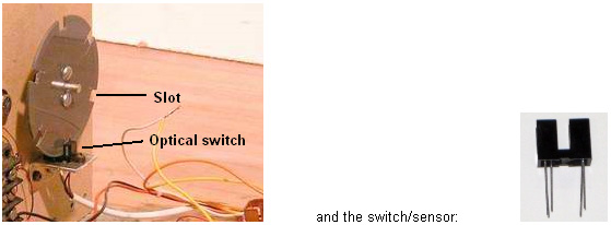 As the slotted disc rotates, one of the slots comes opposite the sensor and allows the UV beam to pass through to the sensor. That lowers the resistance of the sensor device and that change is then used to trigger the drive pulse for whatever length of time the slot leaves the sensor clear. You will notice the balanced attachment method used by Ron to avoid having an unbalanced rotor assembly. There can be two timing discs, one for the drive pulses and one for switching the power pickup coils in and out of the circuit. The slots in the power pick-up timing disk will be very narrow as the switch-on period is only about 2.7 degrees. For a six-inch diameter disc where 360 degrees represents a circumference length of 18.85 inches (478.78 mm) a 2.7 degree slot would be only 9/64 inch (3.6 mm) wide. The arrangement for an axial magnet rotor set-up could be like this:  So to recap, the things which are necessary for getting an Adams Motor output into the serious bracket are: 1. A performance of COP>1 can only be achieved if there are power pick-up coils. 2. The rotor magnets need to be longer than they are wide in order to ensure the correct magnetic field shape and the rotor must be perfectly balanced and have bearings as low-friction as possible. 3. The face area of the rotor magnets needs to be four times that of the drive coil cores and one quarter the area of the core of the power pick-up coils. This means that if they are circular, then the drive coil core diameter needs to be half the diameter of the magnet and the magnet diameter needs to be half the diameter of the power pick-up core. For example, if a circular rotor magnet is 10 mm across, then the drive core should be 5 mm across and the pick-up core 20 mm across. 4. The drive voltage needs to be a minimum of 48 volts and preferably, a good deal higher than that. 5. Do not use neodymium magnets if the drive voltage is less than 120 volts. 6. The drive coils should not be pulsed until they are exactly aligned with the rotor magnets even though this does not give the fastest rotor speed. 7. Each complete set of coils should have a DC resistance of either 36 ohms or 72 ohms and definitely 72 ohms if the drive voltage is 120 volts or higher. 8. Collect the output power in large capacitors before using it to power equipment. If you want the original drawings and some explanation on the operation of the motor, then two publications from the late Robert Adams can be bought from nexusmagazine.com where the prices are quoted in Australian dollars, making the books look much more expensive than they actually are. There is a video on this presentation here. Patrick Kelly http://www.free-energy-info.co.uk http://www.free-energy-info.com |