|
There is nothing magic about free-energy and by “free-energy” I mean something which produces output energy without the need for using a fuel which you have to buy. Free energy devices have been around for a very long time now. I have stood beside a water mill and it’s power is scary as it could crush you in moments and never even notice. That mill is on a quietly flowing small river and it can operate at any time day or night without having to pay anything for the power which it uses. It will have cost quite a bit to build the mill in the first place, but after that, it produces major power year after year. Most free-energy devices are just like that as it costs to build them in the first place, but after that they run for free. This presentation is mainly for people who have never come across free-energy and know nothing about it. So, each chapter deals with just one device and tries to explain it clearly. There is a video on Google which shows an interesting self-powered water-pump driven, electrical generator at: http://www.youtube.com/watch?v=IGpXA6qhH_Q This is a very simple device where the jet of water from the pump is directed at a simple water-wheel which in turn, spins an electrical alternator, powering both the pump and an electric light bulb, demonstrating free-energy. 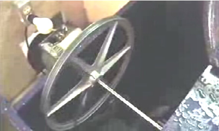 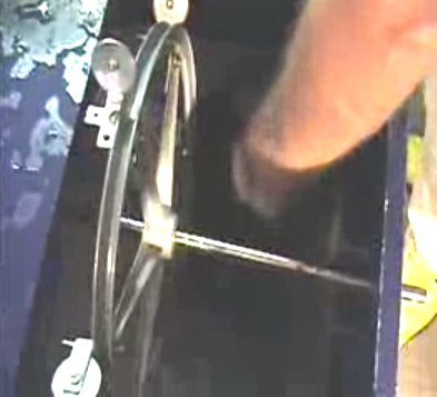 Initially, the generator is got up to speed, driven by the mains electrical supply. Then, when it is running normally, the mains connection is removed and the motor/generator sustains itself and is also able to power at least one light bulb. The generator output is normal mains current from a standard off-the-shelf alternator. James Hardy is the designer and he has Patent Application US 2007/0018461 A1 published in 2007 on his design. In that application he points out that a major advantage of his design is the low noise level produced when the generator is running. In the video and the pictures above, the demonstration has the housing opened up in order to show how the generator system works, but during normal use, the compartments are completely sealed. In his document, James shows the overall system like this:  The housing is divided into three separate compartments. The first compartment has a strong axle shaft running through it, supported on ball or roller bearings – possibly ceramic for this environment. The bearings are protected by being covered by splash guards which keep the water (or other liquid) off them. A waterwheel of almost any type is mounted on the shaft and a high-capacity water pump directs a stream of liquid on to the waterwheel, striking the paddles at right angles in order to provide the maximum impact. This first compartment is sealed in order to contain all of the liquid inside it and the bottom is effectively a sump for the liquid. A pipe located near the bottom of the compartment feeds the liquid to the pump which is located in the second compartment. The pump boosts the liquid through a nozzle, directing it at the waterwheel. While almost any nozzle will work, it is usual to choose one which produces a concentrated jet of liquid in order to generate the largest possible impact. One would expect that the larger the diameter of the waterwheel, the more powerful the system would be. However, that is not necessarily the case as other factors such as the overall weight of the rotating members might affect the performance. Experimentation should show the most effective combination for any given pump. The rotating shaft is given a third bearing supported by the side of the final compartment. The shaft then has a large diameter belt pulley mounted on it, the belt driving a much smaller pulley mounted on the shaft of the generator. This raises the rate at which the generator shaft is rotated. If the pump operates on AC mains voltage, then the generator will be one which generates mains voltage AC. If the pump operates on, say, 12 volts, then the generator will be one which generates 12 volts DC. The diagram above, shows the arrangement for a mains voltage system as that is probably the most convenient. If a 12-volt system is chosen, then the inverter can be omitted. The generator is started by pressing the ‘normally open’ press-button switch marked “A” in the diagram. This passes the battery power through to the 1-kilowatt inverter which then generates AC mains voltage. The switch marked “B” is a “changeover” switch, and for starting, it is set so that it passes the AC power through switch “A” to the pump. This causes the pump to turn on and direct a powerful jet of liquid at the waterwheel, forcing it around and so powering the generator. When the generator gets up to full speed, switch “B” is flipped over, disconnecting the inverter and feeding the generator power through to the pump, keeping it running and supplying additional power to the output power sockets mounted on top of the housing. The press-button switch is released, disconnecting the battery which is no longer needed. Switch “C” is an ordinary On/Off mains switch which is needed if you want to turn the generator off. A major advantage of this generator system is that the main components can be bought ready-made and so only very simple constructional skills and readily available materials are needed. Another advantage is that what is happening can be seen. If the pump is not working, then it is a simple task to discover why. If the generator is not spinning, then you can see that and sort the problem. Every component is simple and straightforward. James suggests that a suitable pump is the 10,000 gallons per hour “Torpedo Pump” from Cal Pump, web site: http://www.calpumpstore.com/products/productdetail/part_number=T10000/416.0.1.1: The housing is divided into three separate compartments. The first compartment has a strong axle shaft running through it, supported on ball or roller bearings – possibly ceramic for this environment. The bearings are protected by being covered by splash guards which keep the water (or other liquid) off them. A waterwheel of almost any type is mounted on the shaft and a high-capacity water pump directs a stream of liquid on to the waterwheel, striking the paddles at right angles in order to provide the maximum impact. This first compartment is sealed in order to contain all of the liquid inside it and the bottom is effectively a sump for the liquid. A pipe located near the bottom of the compartment feeds the liquid to the pump which is located in the second compartment. The pump boosts the liquid through a nozzle, directing it at the waterwheel. While almost any nozzle will work, it is usual to choose one which produces a concentrated jet of liquid in order to generate the largest possible impact. One would expect that the larger the diameter of the waterwheel, the more powerful the system would be. However, that is not necessarily the case as other factors such as the overall weight of the rotating members might affect the performance. Experimentation should show the most effective combination for any given pump. The rotating shaft is given a third bearing supported by the side of the final compartment. The shaft then has a large diameter belt pulley mounted on it, the belt driving a much smaller pulley mounted on the shaft of the generator. This raises the rate at which the generator shaft is rotated. If the pump operates on AC mains voltage, then the generator will be one which generates mains voltage AC. If the pump operates on, say, 12 volts, then the generator will be one which generates 12 volts DC. The diagram above, shows the arrangement for a mains voltage system as that is probably the most convenient. If a 12-volt system is chosen, then the inverter can be omitted. The generator is started by pressing the ‘normally open’ press-button switch marked “A” in the diagram. This passes the battery power through to the 1-kilowatt inverter which then generates AC mains voltage. The switch marked “B” is a “changeover” switch, and for starting, it is set so that it passes the AC power through switch “A” to the pump. This causes the pump to turn on and direct a powerful jet of liquid at the waterwheel, forcing it around and so powering the generator. When the generator gets up to full speed, switch “B” is flipped over, disconnecting the inverter and feeding the generator power through to the pump, keeping it running and supplying additional power to the output power sockets mounted on top of the housing. The press-button switch is released, disconnecting the battery which is no longer needed. Switch “C” is an ordinary On/Off mains switch which is needed if you want to turn the generator off. A major advantage of this generator system is that the main components can be bought ready-made and so only very simple constructional skills and readily available materials are needed. Another advantage is that what is happening can be seen. If the pump is not working, then it is a simple task to discover why. If the generator is not spinning, then you can see that and sort the problem. Every component is simple and straightforward. James suggests that a suitable pump is the 10,000 gallons per hour “Torpedo Pump” from Cal Pump, web site 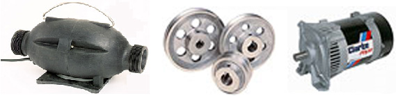 Patrick Kelly http://www.free-energy-info.co.uk http://www.free-energy-info.tuks.nl |