|
We have been raised with the idea that it is necessary to burn a fuel to produce power which we can use. We are sold coal, coke, timber, paraffin/kerosene, petrol/gasoline, diesel, propane, etc. for us to burn in order to “get” energy. While it is perfectly true that burning these things will indeed result in energy in a form which we find convenient to use in heating, cooling, powering engines, etc. what is carefully avoided is the fact that it is not at all necessary to burn a fuel in order to run the things which we want to power. This ‘inconvenient’ fact has been concealed and denied for more than fifty years now (very surprisingly, by the people who want to sell us these fuels to burn – do you perhaps think that they may have some motive for this, other than our best interests which they no doubt are very concerned about?).
This chapter is about ‘fuel-less’ motors. Strictly speaking, they are not ‘self-powered’ but as they don’t burn a fuel of any kind, in everyday language they can be described as ‘self-powered’. In the same way that a solar panel in sunlight uses no fuel and yet puts out electrical power, these motors draw energy from the environment and provide us with mechanical power. In actual fact, power is never “used up” but just converted from one form into another. In the case of our trusty solar panel, some 17% of the radiation from the sun (mainly ultraviolet) is converted into electrical power and 83% goes in heating and other losses, but as we don’t have to supply the sunlight, and the solar panel pours out the electricity which we want without us having to do anything to make it happen, we really don’t care very much about its extremely low efficiency. As far as we are concerned, the electricity flowing from the panel is “free-energy”. It is really amazing that we have been persuaded that we must burn a fuel in order to get power. Take the case of a heavy-displacement sailing yacht. The skipper can voyage using his inboard diesel engine: 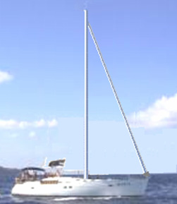 This matches perfectly with the thinking that you need to burn a fuel in order to get power as the yacht is moving along, pushed by the engine which is powered by burning diesel fuel. But, what if the skipper decides to switch the engine off and set the sails?:  Now, the same boat, weighing exactly the same with the same crew, is now continuing the voyage at the same speed, but no fuel is being burnt. The really interesting thing is that while we know this perfectly well, and we are aware that people have sailed right around the world in boats which do not have engines, it does not seem to occur to us that this shows conclusively that it is not necessary to burn a fuel to power some item of equipment or form of transport. In the case of our yacht, the energy comes from the sun which heats the atmosphere unevenly, causing winds to blow and the yachtsman uses the sails to make those winds power his boat through the water. So, a sailing boat is actually powered by the sun although we don’t usually think about it that way. There are many hydro-electric “power stations” where electricity is ‘generated’ by machines driven by water pressure. In actual fact, no power is ‘generated’ at all, but instead, the potential energy of the body of water is converted into electricity by having the water fall and spin the shaft of a machine. So, how did the water get up there in the first place? Well, it came from rain. And how did the rain get up there? It rose up there due to evaporation caused by the heat of the sun. So, the bottom line again is that hydro-electric ‘power’ stations are powered by the sun. Windmills are also powered by the sun. But, and here is the really interesting thing, if I state that it is perfectly possible for a compressed-air engine to produce mechanical power without burning any fuel, then there is an immediate and strong reaction where people will say “Impossible – that is perpetual motion !!” They imply that perpetual motion is impossible but never supply any rational evidence to support that implication. Why then are people so opposed to the idea of perpetual motion? Presumably, because perpetual motion shows clearly that a fuel does not have to be burned to ‘produce’ power and that would not be good for people who sell fuels, and so, we are all told from an early age that perpetual motion is “impossible”. Well, that does not matter here as we are going to look at compressed-air engines which run off the heat of the sun. That is, they are heat-pumps which are a well accepted engineering fact and they work on wholly accepted standard scientific principles. An ordinary refrigerator outputs three or four times as much heat power as the electrical power driving it, and it could be twice that efficient if it were used properly. This is a Coefficient Of Performance (COP) of 3 or 4, which is supposed to be “impossible” but unfortunately, all refrigerators work like this and you can’t exactly say that refrigerators don’t exist, just because their performance does not appear to fit in with some theories. Actually, there is no magic involved here as the extra energy is being drawn from the heat content of the air in the immediate locality. The refrigerator is not operating in isolation and there is a heat exchange with the air surrounding it. This outside energy causes the COP>1 performance. In passing, all COP>1 devices operate by drawing energy in from an external source (usually the zero-point energy field) and none of them actually break the ‘rules’ of science. But, enough of that. The people who don’t want self-powered engines used in the world today, pin their hopes on a continued ignorance of Engineering facts relating to heat pumps. A self-sustaining compressed-air engine is actually running off power from the sun just as sailboats, windmills and hydro-electric power stations do. Sorry folks, no magic here, just bog-standard Engineering. Admittedly, very few people know or realise the implications of this standard Engineering:
Let’s check this out by taking a look at some of the engines which use these principle to provide fuel-less operation, starting with the design of Bob Neal specified in his (slightly re-worded) patent: US Patent 2,030,759 11th Feb. 1936 Inventor: Bob Neal COMPRESSOR UNIT This invention relates to the construction of a compressor, and more particularly to a combined fluid-operated engine and compressor. The primary object of the invention, is the provision of a compressor of this character, wherein there is arranged an automatically counterbalanced crankshaft and fluid equalisers within a storage tank, which makes it possible for the engine to operate on constant reserve tank pressure, so as to actuate additional equipment, the pistons for the engine also being automatically balanced and suspended when the engine is operating. Another object of the invention is the provision of an engine which is operated by air under pressure, the air being supplied by compressors which are in a bank with the engine construction. A further object of this invention is the provision of an engine of this type of novel construction as the engine and the compressors are operated from the same crankshaft, which is of the automatically balanced type, so that high efficiency is attained. A still further object of the invention is the provision of an engine of this character which is comparatively simple in construction, thoroughly reliable and efficient in its operation, strong, durable, and inexpensive to manufacture. With these and other objects in view, the invention consists in the features of construction, combination and arrangement of parts as will be described more fully here, illustrated in the accompanying drawings which disclose the preferred embodiment of the invention, and pointed out in the appended Claim.  In the drawings, Fig.1 is a perspective view of the engine constructed in accordance with the invention.  Fig.2 is a vertical transverse cross-section view through the compressor part of the engine.  Fig.3 is a vertical cross-sectional view through the power part of the engine.  Fig.4 is a detail elevation of the crankshaft of the engine.  Fig.5 is an enlarged cross-sectional view through one of the electric heaters for the engine.  Fig.6 is a vertical, longitudinal, cross-sectional view through the air storage tank, including the equaliser. The same reference numbers are used for each individual part in every view in every drawing. Referring to the drawings in detail, the engine in its entirety, composes a cylinder block 10 having inside it, the series of compressor cylinders 11 and the power cylinders 12. The block 10 is of the V-type and the upper ends of the cylinders are closed off by the removable heads 13 and 14 which are held in place by conventional head bolts 15. Beneath block 10 is the crank case 16, which has detachable plates 17 at opposite sides, held in place by fasteners 18, and seated so as to be leak proof. The block 10 is chambered to provide a water jacket 19 surrounding the cylinders, while at the forward end of the block are water pumps 20, circulating water through the inlet pipe 21 which leads into the jacket and the water exits from the jacket through the outlet pipe 22. Beside the pumps 20, is a fan 23 which is operated from the same belt 24 which drives the pumps. Working inside the cylinders 11,are the reciprocating pistons 25, their rods 26 sliding through packing glands 27 and fixed to crossheads 28 which slide on their mounting guides 29 which are secured to the walls of the crank case 16. These crossheads 28 are fitted with wrist pins 30, forming a pivoting connection with the connecting rods 31, which are connected to their cranks 33 by their bearings 32. The cranks 33 form part of a counter balanced crankshaft 34, which is mounted in supports 35 attached to the crank case 16, the shaft being provided with the required bearings 36. The inner ends of the cylinders 11 are fitted with inner end heads 37, which are provided with air intake ports 38 fitted with spring ball inlet checks 39, the air entering through passages 40 which open outside the block 10. Glands 27 are mounted in the heads 37. The heads 13 and 37 are provided with the compressed air outlets 41 and 42, which are fitted with spring ball checks 43. The heads 13 are also provided with the central air inlets 44, which are fitted with spring checks 45. Couplings 46 attach the air outlets 41 and 42 to their outlet feed pipes 47 and 48. These pipes lead to a main conduit 49 which is located in the centre channel 50 of the block 10. At the rear end of the block 10, mounted on shaft 36, there is a conventional flywheel 51. Working inside the cylinders 12 are the pistons 52, with their piston rods 53 sliding through packing glands 54 and fixed in crossheads 55 which slide along their mounting guides 56, mounted on the inner walls of the crank case 16. The crossheads 55 have wrist pins 57 which provide a pivoting joint for the connecting rods 58 which are connected by their bearings 59 to their cranks 60 of the crank shaft 34, the inner ends of the cylinders 12 being closed by the inner heads 61 and their associated glands 54. On the cylinders 12 are slide valve chests 62 in which are the slide valves 63, these being operated by throw rods 64 actuated by cams 65 and the valves controlling the admission and exhaust of air into and out of the cylinders 12, through the ports 66 and 67, and these valves 63 are provided with ports 68 for the delivery of air under pressure from the inlet passages 69 common to a pipe 70 coming from a compressed air storage tank 71. The bottom of the crank case 16 is fitted with a removable plate 72 which is secured in place by fasteners 73, and when this plate is removed, it provides access to the crank shaft 34 and the bearings for the engine, as well as other parts inside the crank case.  Leading into the cylinders 11 are the passages 74 of a lubricating system (not shown). The compressed air storage tank 71 has inside it a double-check discharge nozzle 75, supported by member 76. Leading to this equaliser is an air inlet pipe 77 which connects through its valved section 78 to the compressed air reservoir 79. In the equaliser 75, are the spaced spring ball checks 80 and 81, one being for the inlet side and the other for the outlet side of the equaliser. This pipe 77 is connected with the main conduit 49, while a pipe 82 connects to pipe 70. The tank is also fitted with an automatic relief valve 83 and this valve can be of any approved type. Placed around the pipes 70 which connect to the air passages 69 (Fig.3) are electric heating units 84 to heat the pressurised air to above freezing temperature when delivered from tank 71 to the cylinders 12. Supported on the block 10 is an electric generator 85 which is driven from the shaft 34 (Fig.2) through a belt 24 (Fig.1) and this generator is included in an electric circuit which also has the heaters 84 so that these will operate from current supplied by the generator. The compressed air storage tank 71 with the equaliser is constructed so that it is possible to pump air into it while it contains an air pressure of 200 pounds per square inch while the compressors are only pumping against 15 pounds per square inch of (atmospheric) pressure. An outside air pressure source can be coupled with the tank to augment that pressure derived from the cylinders 11 of the engine. CLAIMS What is claimed is: In a structure of the kind described, a V-shaped cylinder block provided with upwardly divergent cylinders, end heads fitted to said cylinders at opposite ends thereof, each head having valved inlets and outlets, a main outlet lead between the cylinders of the block for a storage tank and having lateral branches to the outlets at the inner sides of said heads, one inlet being located at the centre of each head at the outer ends of said cylinders while the remaining inlets are at the outer sides of the heads at the inner ends of said cylinders, a substantially V-shaped crank case fitted to the block beneath the cylinders, a counterbalanced crank shaft journaled in the crank case, pistons operating in the cylinders and having rods extended into the crank case, crosshead guides fitted to the interior sides of said case, crossheads connecting the rods with the guides and sliding on them and connecting rods operated by the crank shaft and pivoted at the crossheads in order to allow reciprocation of the pistons. You will notice that Bob has avoided any direct mention of the fact that his engine design is fuel-less. That sort of statement is not popular with Patent Examiners even if it is perfectly true. This system could do with some further explanation, so here is an idea from Scott Robertson's web site, for a possible working compressor system using a leaf-blower:  While this looks rather complicated, in reality it really isn’t. Let’s take the different sections in order:  First, you have an ordinary air engine, supplied with compressed air from a pressure tank. This engine exhausts its (cold, expanded) air to the atmosphere. The engine powers two compressors which between them keep the tank full of compressed air.  The first compressor is a simple ‘leaf-blower’ type which produces a large volume of low-pressure air. The big question is “how do you get this large volume of low-pressure air into a tank which has high-pressure compressed air inside it?”. Well this seemingly impossible task is performed by the second compressor aided by a cunning, ultra-simple design:  Here, low-pressure air is fed into the low-pressure area marked in pink. Separating it from the high-pressure area is a metal plug marked in green. Set into this plug is a ring of five one-way air valves marked in red. These one-way valves let the low-pressure air into the high-pressure area because of a high-speed jet of air produced by the ‘jet-drive compressor’. At first glance, this seems impossible, but it is actually just an application of a standard Engineering technique. The high-speed air jet is directed through a specially shaped nozzle, creating a local low-pressure zone around the jet:  The low-pressure air at point “A” flows through the ring of five one-way valves into the disc-shaped low pressure area “B” and is blasted into the high-pressure area “C” by the high-power air jet ripping through the doughnut-shaped ring marked in yellow. The high-speed air jet causes the low pressure ring “B” by its rapid movement which creates a vortex due to the shape and positioning of the doughnut-shaped ring marked in yellow. This clever arrangement allows large volumes of low-pressure air to be drawn into a tank which contains high-pressure air. You will also note that the two-stage compressor which generates this high-speed jet of air, has its working area actually inside the tank. This means that the heat of compression is used to heat the air inside the tank and raise its pressure, enhancing the operation further. It should be borne in mind that the new air entering the system has been heated by the sun and contains the energy which powers the system. Tesla’s Motionless One-way Valve As it is not widely publicised, many people have never heard of Nikola Tesla’s patent 1,329,559 of 1916 which describes a very clever physical shape which has easy passage of a fluid in one direction but very difficult flow in the opposite direction. This is the shape:  This arrangement is very clever as flow from right to left is free while flow from left to right results in a collision for every loop in the flow path. That is like this:  As a result of this, the larger the number of loops, the greater the flow resistance. With the eleven loops ahown in the patent, the resistance to flow is more than 200 times from left to right. There are many different applicatons for such a fluid diode. The Retro-fit Compressed Air Vehicle System of Leroy Rogers. The Rogers motor shown here makes no claims to spectacular operation, but in spite of that, Leroy did admit in an interview that this motor does indeed have a greater output than the applied input, provided that the motor is not left just ticking over. This motor is like the US patent 3,744,252 “Closed Motive Power System Utilising Compressed Fluids” by Eber Van Valkinburg shown below. However, the Rogers patent shown here has the distinct advantage that it uses off-the-shelf motors and readily available hardware and there is nothing really exotic or difficult about the Rogers engine that a person couldn’t get from a valve supplier or get a metal fabrication company to construct. However, while Leroy did state that his design was self-sustaining when going over 30 miles per hour, a key design feature is his very high performance compressor unit which he later patented as shown below. Present day vehicle engines are under-geared and run at fairly low revs. These same engines operate much more efficiently at higher revs, if they are given different gearing. With the Rogers motor, the air contained in the high-pressure tank is sufficient to drive the pistons up and down. Air can be pumped back into the high-pressure tank by a compressor which has a much higher gearing and much lower capacity per piston stroke. The expanded air exiting from the engine is at much lower temperature than the surrounding air and if it captured in a buffer tank and used as the input of the compressor, then recharging the air tank is more efficient, provided that the tank absorbs heat from the surrounding environment, raising it’s temperature inside the tank and so giving an extra boost to the tank pressure, over and above the compression provided by the compressor. One really nice feature of Leroy’s design is that he envisages it as being an adaption of an ordinary vehicle engine and he provides a considerable amount of practical detail as to how the adaption can be carried out. Using a RotoVerter (as described in Chapter 2) to drive a compressor would lower the power requirements of the compressor drive to the extent that a motor adaption of this kind should be self-sustaining. The RotoVerter provides a major energy gain in its own right and is particularly suited to driving mechanical loads such as the compressor and it particularly ‘likes’ constant-load applications such as a compressor. The adapted engine shown in the patent is like this: . Patent US 4,292,804 6th October 1980 Inventor: Leroy K. Rogers METHOD AND APPARATUS FOR OPERATING AN ENGINE ON COMPRESSED GAS ABSTRACT The present invention relates to a method and apparatus for operating an engine having a cylinder containing a reciprocating piston driven by a compressed gas. The apparatus comprises a source of compressed gas connected to a distributor which conveys the compressed gas to the cylinder. A valve is provided to admit compressed gas to the cylinder when the piston is in an approximately Top Dead Centre position. In one embodiment of the present invention, the timing of the opening of the valve is advanced so that the compressed gas is admitted to the cylinder progressively further before the Top Dead Centre position of the piston as the speed of the engine increases. In a further embodiment of the present invention, a valve actuator is provided which increases the length of time over which the valve remains open to admit compressed gas to the cylinder as the speed of the engine increases. A still further embodiment of the present invention relates to an apparatus for adapting a conventional internal combustion engine for operation on compressed gas. US Patent References: DESCRIPTION BACKGROUND AND SUMMARY OF THE PRESENT INVENTION The present invention is a method and apparatus for operating an engine using a compressed gas as the motive fluid. More particularly, the present invention relates to a apparatus for adapting a pre-existing internal combustion engine for operation on a compressed gas. Air pollution is one of the most serious problems facing the world today. One of the major contributors to air pollution is the ordinary internal combustion engine which is used in most motor vehicles today. Various devices, including many items required by legislation, have been proposed in an attempt to limit the pollutants which an internal combustion engine exhausts to the air. However, most of these devices have met with limited success and are often both prohibitively expensive and complex. A clean alternative to the internal combustion engine is needed to power vehicles and other machinery. A compressed gas, preferably air, would provide an ideal motive fluid for an engine, since it would eliminate the usual pollutants exhausted from an internal combustion engine. An apparatus for converting an internal combustion engine for operation on compressed air is disclosed in U.S. Pat. No. 3,885,387 issued May 27, 1975 to Simington. The Simington patent discloses an apparatus including a source of compressed air and a rotating valve actuator which opens and closes a plurality of mechanical poppet valves. The valves deliver compressed air in timed sequence to the cylinders of an engine through adapters located in the spark plug holes. However, the output speed of an engine of this type is limited by the speed of the mechanical valves and the fact that the length of time over which each of the valves remains open cannot be varied as the speed of the engine increases. Another apparatus for converting an internal combustion engine for operation on steam or compressed air is disclosed in U.S. Pat. No. 4,102,130 issued July 25, 1978 to Stricklin. The Stricklin patent discloses a device which changes the valve timing of a conventional four stroke engine such that the intake and exhaust valves open once for every revolution of the engine instead of once every other revolution of the engine. A reversing valve is provided which delivers live steam or compressed air to the intake valves and is subsequently reversed to allow the exhaust valves to deliver the expanded steam or air to the atmosphere. A reversing valve of this type however does not provide a reliable apparatus for varying the amount of motive fluid injected into the cylinders when it is desired to increase the speed of the engine. Further, a device of the type disclosed in the Stricklin patent requires the use of multiple reversing valves if the cylinders in a multi-cylinder engine were to be fired sequentially. Therefore, it is an object of the present invention to provide a reliable method and apparatus for operating an engine or converting an engine for operation with a compressed gas. A further object of the present invention is to provide a method and apparatus which is effective to deliver a constantly increasing amount of compressed gas to an engine as the speed of the engine increases. A still further object of the present invention is to provide a method and apparatus which will operate an engine using compressed gas at a speed sufficient to drive a conventional automobile at highway speeds. It is still a further object of the present invention to provide a method and apparatus which is readily adaptable to a standard internal combustion engine, to convert the internal combustion engine for operation with a compressed gas. Another object of the invention is to provide a method and apparatus which utilises cool expanded gas, exhausted from a compressed gas engine, to operate an air-conditioning unit and/or an oil-cooler. These and other objects are realised by the method and apparatus of the present invention for operating an engine having at least one cylinder containing a reciprocating piston and using compressed gas as the motive fluid. The apparatus includes a source of compressed gas, a distributor connected it for conveying the compressed gas to the cylinder or cylinders. A valve is provided for admitting the compressed gas to the cylinder when the piston is in an approximately Top Dead Centre position within the cylinder. An exhaust is provided for exhausting the expanded gas from the cylinder as the piston returns to approximately the Top Dead Centre position. In a preferred embodiment of the present invention, a device is provided for varying the duration of each engine cycle over which the valve remains open to admit compressed gas to the cylinder, dependent upon the speed of the engine. In a further preferred embodiment of the present invention, an apparatus for advancing the timing of the opening of the valve is arranged to admit the compressed gas to the cylinder progressively further and further before the Top Dead Centre position of the piston, as the speed of the engine increases. Further features of the present invention include a valve for controlling the amount of compressed gas admitted to the distributor. Also, a portion of the gas which has been expanded in the cylinder and exhausted through the exhaust valve, is delivered to a compressor to be compressed again and returned to the source of compressed gas. A gear train can be engaged to drive the compressor selectively at different operating speeds, depending upon the pressure maintained at the source of compressed air and/or the speed of the engine. Still further, a second portion of the exhaust gas is used to cool a lubricating fluid for the engine or to operate an air-conditioning unit. In a preferred embodiment of the present invention, the valve for admitting compressed gas to the cylinder is operated electrically. The device for varying the duration of each engine cycle, over which the intake valve remains open, as the speed of the engine increases, comprises a rotating element whose effective length increases as the speed of the engine increases, causing a first contact on the rotating element to be electrically connected to a second contact on the rotating element, for a longer period of each engine cycle. The second contact operates the valve causing it to remain in an open position for a longer period of each engine cycle, as the speed of the engine increases. Still further features of the present invention include an adaptor plate for supporting the distributor above the intake manifold of a conventional internal combustion engine after a carburettor has been removed to allow air to enter the cylinders of the engine through the intake manifold and conventional intake valves. Another adaptor plate is arranged over an exhaust passageway of the internal combustion engine to reduce the cross-sectional area of the exhaust passageway. BRIEF DESCRIPTION OF THE DRAWINGS Preferred embodiments of a method and apparatus for operating an engine according to the present invention will be described with reference to the accompanying drawings in which components have the same reference numbers in each drawing. Fig.1 is a schematic representation of an apparatus according to the present invention arranged on an engine:  Fig.2 is a side view of one embodiment of a valve actuator according to the present invention.  Fig.3 is a cross-sectional view taken along the line 3--3 in Fig.2.  Fig.4 is a cross-sectional view of a second embodiment of a valve actuator according to the present invention.  Fig.5 is a view taken along the line 5--5 in Fig.4.  Fig.6 is a cross-sectional view of a third embodiment of a valve actuator according to the present invention;  Fig.7 is a view taken along the line 7--7 in Fig.6.  Fig.8 is a cross-sectional view of a gearing unit to drive a compressor according to the present invention.  DETAILED DESCRIPTION OF THE PREFERRED EMBODIMENTS With reference to Fig.1, an engine block 21 (shown in phantom) having two banks of cylinders with each bank including cylinders 20 having pistons 22 which reciprocate in them in a conventional manner (only one of which is shown in phantom). While the illustrated engine is a V-8 engine, it will be apparent that the present invention is applicable to an engine having any number of pistons and cylinders with the V-8 engine being utilised for illustration purposes only. A compressed gas tank 23 is provided to store a compressed gas at high pressure. It may also be desirable to include a small electric or gas compressor to provide compressed gas to supplement the compressed gas held in the tank 23. In a preferred embodiment, the compressed gas is air which can be obtained from any suitable source.  A line 25 transports the gas withdrawn from the tank 23 when a conventional shut-off valve 27 is open. In addition, a solenoid valve 29 preferably operated by a suitable key-operated engine switch (not shown) is also placed in the line 25. In normal operation, the valve 27 is maintained open at all times with the solenoid valve 29 operating as a selective shut off valve to start and stop the engine 21. A suitable regulating valve 31 is arranged downstream of the solenoid valve 29 and is connected by a linkage 33 to a throttle linkage 35 which is operator-actuated by any suitable apparatus such as a foot pedal (not shown). The line 25 enters an end of a distributor 33 and is connected to an end of a pipe 35 which is closed at the other end. A plurality of holes, which are equal to the number of cylinders in the engine 21, are provided on either side of the pipe 35 along the length of the pipe 35. When the present invention is used to adapt a conventional internal combustion engine for operation on compressed gas, an adaptor plate 36 is provided to support the distributor 33 in spaced relation from the usual intake opening in the intake manifold of the engine after a conventional carburettor has been removed. In this way, air is permitted to enter the internal combustion engine through the usual passageways and to be admitted to the cylinders through suitable intake valves (not shown). The adaptor plate 36 is attached to the engine block 21 and the distributor 33 by any suitable apparatus, e.g., bolts. Each of the holes in the pipe 35 is connected in fluid-tight manner to a single line 37. Each line 37 carries the compressed gas to a single cylinder 20. In a preferred embodiment, each of the lines 37 is 1/2 inch high pressure plastic tubing attached through suitable connectors to the distributor 33 and the pipe 35. Each of the lines 37 is connected to a valve 39 which is secured in an opening provided near the top of each of the cylinders 20. In the case of a conversion of a standard internal combustion engine, the valves 39 can be conveniently screwed into a tapped hole in the cylinder 20 typically provided for a spark plug of the internal combustion engine. In a preferred embodiment, the valves 39 are solenoid actuated valves in order to provide a fast and reliable opening and closing of the valves 39. Each of the valves 39 is energised by a valve actuator 41 through one of a plurality of wires 43. The valve actuator 41 is driven by a shaft of the engine similar to the drive for a conventional distributor of an internal combustion engine. That is, a shaft 55 of the valve actuator 41 is driven in synchronism with the engine 21 at one half the speed of the engine 21. A first embodiment of the valve actuator 41 (Fig.2 and Fig.3), receives electrical power through a wire 45 which is energised in a suitable manner by a battery, and a coil if necessary (not shown) as is conventional in an internal combustion engine. The wire 45 is attached to a central post 47 by a nut 49. The post 47 is connected to a conducting plate 51 arranged in a housing 53 for the valve actuator 41. Within the housing 53, the shaft 55 has an insulating element 57 secured to an end of the shaft 55 and rotates with it when the shaft 55 is driven by the engine 21. A first end of a flexible contact 59 is continuously biased against the conducting plate 51 to receive electricity from the battery or other suitable source. The other end of the contact 59 is connected to a conducting sleeve 60 which is in constant contact with a spring biased contact 61 which is arranged within the sleeve 60. The contact 61 is pressed by a spring 63 which pushes contact 61 towards a side wall of the housing 53. With reference to Fig.3, a plurality of contacts 65 are spaced from one another and are arranged around the periphery of the housing 53 at the same level as the spring biased contact 61. Each contact 65 is electrically connected to a post 67 which extends outside of the housing 53. The number of contacts 65 is equal to the number of cylinders in the engine 21. One of the wires 43, which actuate the valves 39, is secured to each of the posts 67. In operation, as the shaft 55 rotates in synchronism with the engine 21, the insulating element 57 rotates and electricity is ultimately delivered to successive pairs of the contacts 65 and wires 43 through the spring loaded contact 61 and the flexible contact 59. In this way, each of the electrical valves 39 is activated and opened in the proper timed sequence to admit compressed gas to each of the cylinders 20 to drive the pistons 22 on a downward stroke. The embodiment illustrated in Fig.2 and Fig.3 is effective in causing each of the valves 39 to remain open for a long enough period of time to admit sufficient compressed gas to each of the cylinders 20 of the engine 21 to drive the engine 21. The length of each of the contacts 65 around the periphery of the housing 53 is sufficient to permit the speed of the engine to be increased when desired by the operator by moving the throttle linkage 35 which actuates the linkage 33 to further open the regulating valve 31 to admit more compressed gas from the tank 23 to the distributor 33. However, it has been found that the amount of air admitted by the valves 39 when using the first embodiment of the valve actuator 41 (Fig.2 and Fig.3) is substantially more than required to operate the engine 21 at an idling speed. Therefore, it may be desirable to provide a valve actuator 41 which is capable of varying the duration of each engine cycle over which the solenoid valves 39 are actuated, i.e., remain open to admit compressed gas, as the speed of the engine 21 is varied. A second embodiment of a valve actuator 41 which is capable of varying the duration of each engine cycle over which each of the valves 39 remains open to admit compressed gas to the cylinders 20 dependent upon the speed of the engine 21 will be described with reference to Fig.4 and Fig.5 wherein members corresponding to those of Fig.2 and Fig.3 bear like reference numbers. The wire 45 from the electricity source is attached to the post 47 by the nut 49. The post 47 has a annular contact ring 69 electrically connected to an end of the post 47 and arranged within the housing 53. The shaft 55 rotates at one half the speed of the engine as in the embodiment of Fig.2 and Fig.3. At an upper end of the shaft 55, a splined section 71 receives a sliding insulating member 73. The splined section 71 of the shaft 55 holds the insulating member 73 securely as it rotates with shaft 55 but permits the insulating member 73 to slide axially along the length of the splined section 71. Near the shaft 55, a conductive sleeve 72 is arranged in a bore 81 in an upper surface of the insulating element 73 generally parallel to the splined section 71. A contact 75, biased towards the annular contact ring 69 by a spring 77, is arranged within the conductive sleeve 72 and in contact with it. The conductive sleeve 72 also contacts a conductor 79 at a base of the bore 81. The conductor 79 extends to the upper surface of the insulating element 73 near an outer periphery of the insulating element 73 where the conductor 79 is electrically connected to a flexible contact 83. The flexible contact 83 connects, one after the other, with a series of radial contacts 85 which are positioned on an upper inside surface of the housing 53. A weak spring 87 arranged around the splined section 71 engages a stop member 89 secured on the shaft 55 and the insulating element 73 to slightly bias the insulating element 73 towards the upper inside surface of the housing 53 to ensure contact between the flexible contact 83 and the upper inside surface of the housing 53. As best seen in Fig.5, the radial contacts 85 on the upper inside surface of the housing 53 are arranged generally in the form of radial spokes extending from the centre of the housing 53 with the number of contacts being equal to the number of cylinders 20 in the engine 21. The number of degrees covered by each of the radial contacts 85 gradually increases as the distance from the centre of the upper inside surface of the housing 53 increases. In operation of the device of Fig.4 and Fig.5, as the shaft 55 rotates, electricity flows along a path through the wire 45 down through post 47 to the annular contact member 69 which is in constant contact with the spring biased contact 75. The electrical current passes through the conductive sleeve 72 to the conductor 79 and then to the flexible contact 83. As the flexible contact 83 rotates along with the insulating member 73 and the shaft 55, the tip of the flexible contact 83 successively engages each of the radial contacts 85 on the upper inside of the housing 53. As the speed of the shaft 55 increases, the insulating member 73 and the flexible contact 83 attached to it, move upwards along the splined section 71 of the shaft 55 due to the radial component of the splines in the direction of rotation under the influence of centrifugal force. As the insulating member 73 moves upwards, the flexible contact 83 is bent so that the tip of the contact 83 extends further outwards radially from the centre of the housing 53 (as seen in phantom lines in Fig.4). In other words, the effective length of the flexible contact 83 increases as the speed of the engine 21 increases. As the flexible contact 83 is bent and the tip of the contact 83 moves outwards, the tip remains in contact with each of the radial contacts 85 for a longer period of each engine cycle due to the increased angular width of the radial contacts with increasing distance from the centre of the housing 53. In this way, the length of time over which each of the valves 39 remains open is increased as the speed of the engine is increased. Thus, a larger quantity of compressed gas or air is injected into the cylinders as the speed increases. Conversely, as the speed decreases and the insulating member 73 moves downwards along the splined section 71, a minimum quantity of air is injected into the cylinder due to the shorter length of the individual radial contact 85 which is in contact with the flexible contact 83. In this way, the amount of compressed gas that is used during idling of the engine 21 is at a minimum whereas the amount of compressed gas which is required to increase the speed of the engine 21 to a level suitable to drive a vehicle on a highway is readily available. Shown in Fig.6 and Fig.7, is a third embodiment of a valve actuator 41 according to the present invention. This embodiment includes a curved insulating element 91 having it’s first end able to pivot, being secured by any suitable device such as screw 92 to the shaft 55 for co-rotation with the shaft 55. The screw 92 is screwed into a tapped hole in the insulating element 91 so that a tab 94 at an end of the screw 92 engages a groove 96 provided in the shaft 55. In this way, the insulating element 91 rotates positively with the shaft 55. However, as the shaft 55 rotates faster, the other end 98 of the insulating element 91 is permitted to pivot outwards under the influence of centrifugal force because of the groove 96 provided in the shaft 55. A spring 93, connected between the second end 98 of the element 91 and the shaft 55 urges the second end of the element 91 towards the centre of the housing 53. A contact 99 similar to the contact 59 (Fig.2) is arranged so that one end of the contact piece 99 is in constant contact with the conducting plate 51 located centrally within the housing 53. The other end of the contact 99 engages a conductive sleeve 101 arranged in bore 102. A contact element 95 is arranged in the conductive sleeve 101 in constant contact with the sleeve 101. The bore 102 is arranged generally parallel to the shaft 55 near the second end of the curved insulating element 91. The contact 95 is biased by a spring 97 towards the upper inside surface of the housing 53 for selective contact with each of the plurality of radial contacts 85 which increase in arc length towards the outer peripheral surface of the housing 53 (Fig.6). When the device shown in Fig.6 and Fig.7 is operating, as the shaft 55 rotates the curved insulating element 91 rotates with the shaft 55 and the second end 98 of the insulating element 91 tends to pivot about the shaft 55 due to centrifugal force. Thus, as the effective length of the contact 95 increases, i.e., as the curved insulating element 91 pivots further outwards, the number of degrees of rotation over which the contact 95 is in contact with each of the radial contacts 85 on the upper inside surface of the housing 53 increases thereby allowing each of the valves 39 to remain open for a longer period of each engine cycle, which in turn, allows more compressed gas enter the respective cylinder 20 to further increase the speed of the engine 21. With reference to Fig.1, a mechanical advance linkage 104 which is connected to the throttle linkage 35, advances the initiation of the opening of each valve 39 such that compressed gas is injected into the respective cylinder further before the piston 22 in the respective cylinder 20 reaches a Top Dead Centre position as the speed of the engine is increased by moving the throttle linkage 35. The advance linkage 104 is similar to a conventional standard mechanical advance employed on an internal combustion engine. In other words, the linkage 104 varies the relationship between the angular positions of a point on the shaft 55 and a point on the housing 53 containing the contacts. Alternatively, a conventional vacuum advance could also be employed. By advancing the timing of the opening of the valves 39, the speed of the engine can more easily be increased. The operation of the engine cycle according to the present invention will now be described. The compressed gas injected into each cylinder of the engine 21 drives the respective piston 22 downwards to rotate a conventional crankshaft (not shown). The movement of the piston downwards causes the compressed gas to expand rapidly and cool. As the piston 22 begins to move upwards in the cylinder 20 a suitable exhaust valve (not shown), arranged to close an exhaust passageway, is opened by any suitable apparatus. The expanded gas is then expelled through the exhaust passageway. As the piston 22 begins to move downwards again, a suitable intake valve opens to admit ambient air to the cylinder. The intake valve closes and the ambient air is compressed on the subsequent upward movement of the piston until the piston reaches approximately the Top Dead Centre position at which time the compressed gas is again injected into the cylinder 20 to drive the piston 22 downwards and the cycle begins again. In the case of adapting a conventional internal combustion engine for operation on compressed gas, a plurality of plates 103 are arranged, preferably over an end of the exhaust passageways, in order to reduce the outlet size of the exhaust passageways of the conventional internal combustion engine. In the illustrated embodiment, a single plate having an opening in the centre is bolted to the outside exhaust passageway on each bank of the V-8 engine, while another single plate having two openings in it, is arranged with one opening over each of the interior exhaust passageways on each bank of the V-8 engine. A line 105 is suitably attached to each of the adaptor plates to carry the exhaust to an appropriate location. In a preferred embodiment, the exhaust lines 105 are made from 1.5" plastic tubing. In a preferred embodiment, the exhaust lines 105 of one bank of the V-8 engine are collected in a line 107 and fed to an inlet of a compressor 109. The pressure of the exhaust gas emanating from the engine 21 according to the present invention is approximately 25 p.s.i. In this way, the compressor 109 does not have to pull the exhaust into the compressor since the gas exhausted from the engine 21 is at a positive pressure. The positive pressure of the incoming fluid increases the efficiency and reduces wear on the compressor 109. The exhaust gas is compressed in the compressor 109 and returned through a line 111 and a check valve 113 to the compressed gas storage tank 23. The check valve 113 prevents the flow of compressed gas stored in the tank 23 back towards the compressor 109. A suitable pressure sensor 115 is arranged at an upper end of the tank 23 and sends a signal along a line 117 when the pressure exceeds a predetermined level and when the pressure drops below a predetermined level. The line 117 controls an electrically activated clutch 119 positioned at the front end of the compressor 109. The clutch 119 is operated to engage and disengage the compressor 109 from a drive pulley 121. Also, the signal carried by the line 117 activates a suitable valve 123 arranged on compressor housing 125 to exhaust the air entering the compressor housing 125 from the line 107 when the clutch 119 has disengaged the compressor 109 from the drive pulley 121. In a preferred embodiment, when the pressure is the tank 23 reaches approximately 600 p.s.i., the clutch 119 is disengaged and the compressor 109 is deactivated and the valve 123 is opened to exhaust the expanded gas delivered to the compressor 109 from the line 107 to the atmosphere. When the pressure within the tank 23 drops below approximately 500 p.s.i., the sensor 115 sends a signal to engage the clutch 119 and close the valve 123, thereby operating the compressor 109 for supplying the tank 23 with compressed gas. The pulley 121 which drives the compressor 109 through the clutch 119 is driven by a belt 127 which is driven by a pulley 129 which operates through a gear box 131. With reference to Fig.1 and Fig.8, a second pulley 133 on the gear box is driven by a belt 135 from a pulley 137 arranged on a drive shaft 139 of the engine 21. The pulley 137 drives a splined shaft 140 which has a first gear 141 and a second larger gear 143 placed on it, which rotates with the splined shaft 140. The splined shaft 140 permits axial movement of the gears 141 and 143 along the shaft 140. In normal operation (as seen in Fig.8), the first gear 141 engages a third gear 145 arranged on a shaft 147 which drives the pulley 129. The shafts 140 and 147 are arranged in suitable bearings 149 positioned at each end of it. When the speed of the engine 21 drops below a predetermined level, a suitable sensor 151 responsive to the speed of the drive shaft 139 of the engine 21 generates a signal which is transmitted through a line 153 to a solenoid actuator 155 arranged within the gear box 131. The solenoid actuator 155 moves the first and second gears 141, 143 axially along the splined shaft 140 to the right as seen in Fig.8 so that the second, larger gear 143 engages a fourth smaller gear 157 which is arranged on the shaft 147. The ratio of the second gear 143 to the fourth gear 157 is preferably approximately 3 to 1. In this way, when the speed of the engine 21 drops below the predetermined level as sensed by the sensor 151 (which predetermined level is insufficient to drive the compressor 109 at a speed sufficient to generate the 500-600 pounds of pressure which is preferably in the tank 23), the solenoid actuator 155 is energised to slide the gears 143, 141 axially along the splined shaft 140 so that the second, larger gear 143 engages the fourth, smaller gear 157 to drive the pulley 129 and hence the compressor 109 at a higher rate, to generate the desired pressure. When the speed of the engine increases above the predetermined level, which, in a preferred embodiment is approximately 1500 rpm, the solenoid actuator 155 is deactivated by the sensor 151 thereby moving the gears 143 and 141 to the left as seen in Fig.8 so that the first gear 141, engages again with the third gear 145 to effectuate a 1 to 1 ratio between the output shaft 139 of the engine 21 and the pulley 129. The other bank of the V-8 engine has its exhaust ports arranged with adapter plates 103 similar to those on the first bank. However, the exhaust from this bank of the engine 21 is not collected and circulated through the compressor 109. In a preferred embodiment, a portion of the exhaust is collected in a line 159 and fed to an enlarged chamber 161. A second fluid is fed through a line 163 into the chamber 161 to be cooled by the cool exhaust emanating from the engine 21 in the line 159. The second fluid in the line 163 may be either transmission fluid contained in a transmission associated with the engine 21 or a portion of the oil used to lubricate the engine 21. A second portion of the exhaust from the second bank of the V-8 engine is removed from the line 159 in a line 165 and used as a working fluid in an air conditioning system or for any other suitable use. It should be noted that the particular arrangement utilised for collecting and distributing the gas exhausted from the engine 21 would be determined by the use for which the engine is employed. In other words, it may be advantageous to rearrange the exhaust tubing such that a larger or smaller percentage of the exhaust is routed through the compressor 109. It should also be noted that since the exhaust lines 105 are plastic tubing, a rearrangement of the lines for a different purpose is both simple and inexpensive. In operation of the engine of the present invention, the engine 21 is started by energising the solenoid valve 29 and any suitable starting device (not shown), e.g., a conventional electric starter as used on an internal combustion engine. Compressed gas from the full tank 23 flows through the line 25 and a variable amount of the compressed gas is admitted to the distributor 33 by controlling the regulator valve 31 through the linkage 33 and the operator actuated throttle linkage 35. The compressed gas is distributed to each of the lines 37 which lead to the individual cylinders 20. The compressed gas is admitted to each of the cylinders 20 in timed relationship to the position of the pistons within the cylinders by opening the valves 39 with the valve actuator 41. When it is desired to increase the speed of the engine, the operator moves the throttle linkage 35 which simultaneously admits a larger quantity of compressed gas to the distributor 33 from the tank 23 by further opening the regulator valve 31. The timing of the valve actuator 41 is also advanced through the linkage 104. Still further, as the speed of the engine 21 increases, the effective length of the rotating contact 83 (Fig.4) or 95 (Fig.6) increases thereby electrically contacting a wider portion of one of the stationary radial contacts 85 to cause each of the valves 39 to remain open for a longer period of each engine cycle to admit a larger quantity of compressed gas to each of the cylinders 20. As can be seen, the combination of the regulating valve 31, the mechanical advance 104, and the valve actuator 41, combine to produce a compressed gas engine which is quickly and efficiently adaptable to various operating speeds. However, all three of the controls need not be employed simultaneously. For example, the mechanical advance 104 could be utilised without the benefit of one of the varying valve actuators 41 but the high speed operation of the engine may not be as efficient. By increasing the duration of each engine cycle over which each of the valves 39 remains open to admit compressed gas to each of the cylinders 20 as the speed increases, conservation of compressed gas during low speed operation and efficient high speed operation are both possible. After the compressed gas admitted to the cylinder 20 has forced the piston 22 downwards within the cylinder to drive the shaft 139 of the engine, the piston 22 moves upwards within the cylinder 20 and forces the expanded gas out through a suitable exhaust valve (not shown) through the adapter plate 103 (if employed) and into the exhaust line 105. The cool exhaust can then be collected in any suitable arrangement to be compressed and returned to the tank 23 or used for any desired purpose including use as a working fluid in an air conditioning system or as a coolant for oil. When using the apparatus and method of the present invention to adapt a ordinary internal combustion engine for operation with compressed gas it can be seen that considerable savings in weight are achieved. For example, the ordinary cooling system including a radiator, fan, hoses, etc. can be eliminated since the compressed gas is cooled as it expands in the cylinder. In addition, there are no explosions within the cylinder to generate heat. Further reductions in weight are obtained by employing plastic tubing for the lines which carry the compressed gas between the distributor and the cylinders and for the exhaust lines. Once again, heavy tubing is not required since there is little or no heat generated by the engine of the present invention. In addition, the noise generated by an engine according to the present invention is considerably less than that generated by an ordinary internal combustion engine since there are no explosions taking place within the cylinders. This patent shows how the practical details of running an engine on compressed air can be dealt with. What it does not show is background details of the actual energy flows and the effects of compressing air and then letting it expand. These things are not normally encountered in our daily lives and so we do not have an immediate intuitive feel for how a system like these will operate. Take the effects of expansion. While it is quite well known that letting a compressed gas expand causes cooling, the practical effect is seldom realized. Leroy’s compressor patent is shown here: Inventor: Rogers Sr., Leroy K. (Rte. 13, P.O. Box 815-DD, Briarcliff Rd., Fort Myers, FL, 33908) Publication Date: 15th September 1987 Abstract: A supercharger for delivering supercharged air to an engine, comprising a shrouded axial compressor, a radial compressor which is located downstream of the axial compressor and a housing. The housing is comprised of four sections, including a section which is a highly converging, ‘frustoconical’ transition duct which favourably directs the discharge of the axial compressor to the inlet of the radial compressor and a hollow, highly convergent, exhaust cone section immediately downstream of the radial compressor which converges into the exhaust port of the supercharger. An annular flow deflector is provided for directing the discharge of the radial compressor into the exhaust cone. Description: Superchargers impart additional pressure to the air or the air/fuel mixture of an engine so that the cylinders receive a greater weight per unit volume of air or air/fuel mixture than would otherwise be supplied. As a result, the volumetric efficiency and power output of the engine are improved. According to prior practices, superchargers generally comprise a single air-blower which forces air or an air/fuel mixture into the cylinders of an engine. Typically, the air-blower is driven by a gear train which is connected to the crankshaft of the engine with a gear ratio of about 6 to 1. These prior types of superchargers have been used extensively in racing engines and radial aircraft engines. However, by reason of their high operating speeds and their gear trains, these superchargers have been considered too complicated, too heavy and too costly for use with mass production engines such as are found in cars and trucks. Recently, some car manufacturers have been offering turbocharged engines which expand to exhaust gases of the engine through a turbine to drive a centrifugal compressor. Although turbochargers are advantageous in that the turbine can deliver large amounts of power to the compressor, their extreme operating speeds require special bearings, lubrication and maintenance. In addition, turbochargers require special ducting, such as by-pass arrangements, which only add to their cost and maintenance requirements. Consequently, turbochargers are only offered as expensive options in cars. Further, there is current interest in a new type of car engine which operates from tanks of compressed gas to effect reciprocation of its pistons. An example of such an engine can be found in the U.S. Pat. No. 4,292,804 issued to the same inventor of the present invention. In the referenced patent, at least a portion of the partially expanded exhaust gas from the cylinders is directed to a compressor where it is recompressed and then returned to the storage tanks from whence it originally came. It would be desirable that at least some, if not all of the aforementioned recompression of the exhaust gas could be achieved with a belt-driven, rotary supercharger that is easily manufactured and maintained, yet is capable of providing ample recompression. Objects of the Invention: Accordingly, an object of the present invention is to provide a supercharger suitable for improving the performance of engines of cars, helicopters or the like, which supercharger is inexpensive to produce and easy to maintain. It is another object of the present invention to provide a supercharger which provides sufficient boost without resort to extreme operating speeds and accordingly avoids the costly complications associated with high speed operation. It is yet another object of the present invention to provide a relatively compact and lightweight supercharger which is inexpensive to manufacture and maintain. Another object of the present invention is to provide a belt-driven supercharger having a design which provides supercharging compression at relatively low operating speeds. It is still another object of the present invention to provide a supercharger which can be quite readily disassembled and reassembled for purposes of low cost maintenance and repair. Still another object of the present invention is to provide a supercharger which can be constructed from mass producible parts to thereby reduce the cost of its manufacture. It is still another object of the present invention to provide a belt-driven supercharger which provides supercharging compression without resort to a larger number of compressor stages. Yet another object of the present invention is to provide a rotary supercharger for a gas operated engine, which supercharger is easily manufactured and maintained, yet capable of providing ample recompression of the recirculating drive fluid.  Summary of the Invention: These and other objects are achieved by the present invention which provides a supercharger comprising a housing having an inlet and an outlet, a shrouded axial compressor and a radial compressor rotatably mounted within the housing, a highly convergent shallow, frustoconical transition duct for favourably directing the discharge of the axial compressor to the inlet of the radial compressor. In accordance with a further aspect of the invention, the above-described supercharger further comprises an exhaust cone at a location downstream of the radial compressor and a flow deflector for directing the discharge of the radial compressor to the exhaust cone. In the preferred embodiment, the housing itself comprises four sections: a cylindrical front housing section which defines an axially directed inlet; a second, cylindrical ducting section enclosing the axial compressor; a rear housing section defining the transition duct as well as the inlet and casing for the radial compressor; and the exhaust cone section which defines at its terminus the outlet of the housing. For driving the compressor shaft, a double-tracked pulley wheel is secured to the forward end of the common shaft, which pulley wheel is adapted to receive one or more drive belts from the crank-shaft wheel of the engine. A lateral opening in the front housing section accommodates the connection with the drive belts. With the disclosed arrangement, compression can be achieved for supercharging purposes without resort to a large number of compressor stages or high operating speeds. Additionally, the design of the disclosed supercharger avoids the need for guide vanes between the axial compressor and the radial compressor. The exhaust cone section also favourably avoids the build-up of back pressure against the radial compressor. The design is also very simple and therefore inexpensive to manufacture and maintain. Other objects, advantages and novel features of the present invention will become apparent from the following detailed description of the invention when considered in conjunction with the accompanying drawing. Brief description of the Drawings: A preferred embodiment of the present invention is described in greater detail with reference to the accompanying drawing wherein like elements bear like reference numerals, and where:  Fig.1 is a cross-sectional side view of a supercharger constructed in accordance with the preferred embodiment of the present invention;  Fig.2 is a side view of the supercharger of Fig.1;  Fig.3 is a frontal view of the impeller of the supercharger of Fig.1;  Fig.4 is a cross-sectional view taken along line 4--4 of Fig.1;  Fig.5 is a cross-sectional view taken along line 5--5 in Fig.1;  Fig.6 is a cross-sectional view taken along line 6--6 in Fig.1;  Fig.7 is a perspective view of a segment of the impeller of the supercharger of Fig.1; and  Fig.8 is a partial side view of the supercharger of Fig.1 with an adaptor . Detailed Description of the Preferred Embodiment: Referring to Fig.1 and Fig.2, a supercharger 10 is provided for supplying supercharged air to a car engine or the like, so that the engine receives a greater weight per unit volume of air or a fuel/air mixture than would be otherwise supplied. In accordance with a preferred embodiment of the present invention, the supercharger 10 comprises a housing 12 having an axially directed inlet 14 for receiving ambient air and an axially directed outlet 16 for delivering supercharged air to the intake of the car engine. Rotatably mounted within the housing 12 is a shaft 18 on which are secured an axial compressor 24 and a radial compressor 26, which is positioned downstream of the axial compressor. A pulley wheel 28 is secured to a forward end 30 of the shaft for receiving drive belts 31, which drive belts connect the shaft 18 to a pulley wheel on the crankshaft of the engine (not shown). The drive belts 31 deliver torque to the shaft 18 as required for driving the compressors 24 and 26 of the supercharger 10. Housing 12 is constructed from four sections which are preferably bolted together at flanged connections in an end-to-end relationship. These sections include a front housing section 32, an axial compressor duct section 34, a rear housing section 36 and an exhaust cone section 38. The shaft 18 extends along the longitudinal axis of the housing 12. The front housing section 32 is a hollow cylinder which extends forward of a front bearing support 40. The front housing section 32 encloses the forward end 30 of the shaft 18 and the associated pulley wheel 28. At its forward end, the front housing section 32 defines the inlet 14 for receiving air from an external source (not shown). Referring particularly to Fig.2, the front housing section 32 includes a lateral opening 44 on one side in order to accommodate the connection of the drive belts 31 to the pulley wheel 28. The front housing section 32 also includes a forward flange 46 for accommodating the connection of air filters, carburettors, air scoops or the like upstream of the supercharger 10 according to the particular engine layout. It is to be understood that in the usual engine layout, the supercharger 10 receives air or a fuel/air mixture from an external source through its inlet 14, compresses the air or fuel/air mixture and then delivers it to the intake of the engine. Referring again to Fig.1, the pulley wheel 28 is interference-fitted upon the forward end 30 of shaft 18 and a key 134 is used to lock the pulley wheel 28 in place. The pulley wheel 28 is preferably a double-track design which is suitable for the attachment of twin drive belts, although a single-belt type pulley wheel would be adequate. The pulley wheel 28 is preferably sized so that the ratio of it’s diameter with respect to the diameter of the drive wheel of the engine's crankshaft provides an effective gearing ratio in the range of approximately two and one-half to four and one-half. Thus at idle, when the car engine is running at approximately 700 rpm, the supercharger 10 is running at approximately 2,400 rpm, and at cruise, when the engine is running around 2,500 rpm, the supercharger 10 is preferably turning over in the range of 6,000 to 8,000 rpm. It is to be noted that although the diameter of the pulley wheel 28 may be substantially reduced in order to achieve a desired gearing ratio, the double-track wheel 28 presents a sufficient sum total of surface area to avoid slippage of the belts 31. The next adjacent section of housing 12 is the axial compressor duct 34 which is a short cylinder coaxially disposed about the axial compressor 24. Preferably, the axial compressor duct 34 is constructed from cast aluminium, with the interior surfaces 48 machined to assure uniform clearance between the duct 34 and shroud 50 of the axial compressor 24. As with other sections of the housing 12, the axial compressor duct 34 is provided with flanges 52 and 54 for effecting connection to the adjacent housing sections. The axial compressor duct 34 guides air delivered from the front housing section 32 towards the axial compressor 24. Referring now to Fig.1 and Fig.4, a front bearing support 40 is placed between the front housing section 32 and the axial compressor duct 34. The front bearing support 40 includes an outer annulus 56 and three radial arms 58. Between these arms are defined passages 60 for allowing air to pass through the bearing support 40. The outer annulus 54 is secured by bolts connecting a rear flange 64 of the front housing section 32 and the flange 52 of the axial compressor duct 34. By this arrangement, the front bearing support 40 is rigidly secured to the housing 12 so that loads and shocks to the shaft 18 can be transferred through the front bearing support 40 to the housing 12. In the preferred embodiment, the outer annulus 56 of the bearing support 40 extends into the region of the inlet 14 of the front housing section 32 in such a way that it’s inner rim 68 coincides with the inner rim 70 of the shroud 50 of the axial compressor 24. In this way, the outer annulus 56 contributes to the guiding of the flow of air toward the axial compressor 24. An outer raceway 74 of the front roller bearing assembly 76 is secured between the front bearing support 40 and a bearing retainer plate 78, which is secured by the removable bolts 80. In this preferred embodiment, the front bearing assembly 76 is of the sealed, high speed type. A suitable commercially available bearing assembly is marketed under the reference: model Fafnir 405KDD. Preferably, a lower raceway 82 of the front bearing assembly 76 is secured to the shaft 18 with an interference fit. A spacer 84 is provided on one side of the lower raceway 82, which spacer 84 also abuts a hub 86 of the axial compressor 24 in order to position the axial compressor 24 at a predetermined distance downstream of the bearing support 40. Similarly, a spacer 88 is provided on the other side of the lower raceway 84, and it abuts the pulley wheel 28 so as to space apart the pulley wheel 28 from the front bearing support 40 to ensure that there is sufficient clearance between them. It should be appreciated that the bearing retainer plate 78 allows ready access to the front bearing assembly 76 for purposes of maintenance or repair. To service the front bearing assembly 76, a nut 90 and lock-washer 92 on the forward end 30 of the shaft 18 are loosened and removed together with the pulley wheel 28 and the spacer 88. Then bolts 42 and the bearing retainer plate 76 are removed, leaving the whole bearing assembly 76 exposed for servicing and/or removal. The rear housing section 36 is connected by bolts to the downstream end of the axial compressor duct 34. Preferably, the rear housing section 36 is constructed from a single section of cast aluminium and includes external longitudinal ribs 94 for enhancing the structural rigidity of the rear housing section 34. The walls of the rear housing section 36 define three elements of the supercharger 10: a highly conical transition duct 96 which favourably directs the output of the axial compressor to an inlet 98 of the radial compressor 26; the inlet 98 of the radial compressor 26, itself; and a casing 100 for the radial compressor 26. The transition duct 96 is a hollow, frustoconical portion having a half-apex angle (from the generatrix to the axis of symmetry) of approximately 35°. The angle is selected such that the inlet to the radial compressor 26 is as close as possible to the outlet of the axial compressor, without causing undue back-pressure. In the preferred embodiment, the transition duct 96 begins a short distance downstream of the axial compressor 24 and ends at the beginning of the inlet 98 of the radial compressor 26. The highly conical shape of the transition duct 96 is believed to roll-in the higher volume of air being discharged from the more radially outward portions of the axial compressor 24. This rolling-in action is believed to promote a favourable flow regime at the inlet 98 of the radial compressor 26 so that there is no need for inlet guide vanes for the radial compressor 26. It is also believed that the highly conical shape of the transition duct 96 affects upstream flow conditions at the axial compressor 24 in such a way that it’s performance is improved. It has also been found that there is no need for a stator (or exit guide vane) for the axial compressor 24. In essence, it is believed that the transition duct 96 performs the functions of the exit vanes of axial compressors and inlet guide vanes of radial compressors, but without the pressure losses commonly associated with them. Avoiding these pressure losses and the expected improvement in the performance of the axial compressor, allows the supercharger 10 to impart a higher overall pressure ratio than would otherwise be achieved without the transition duct 96. As a result, adequate compression is achieved at moderate operating speeds without resort to a bank of several axial compressors. It should be understood however, that when connecting the supercharger 10 to a relatively slowly reciprocating diesel or a very large engine, it may be desirable to include two or more axial compressors in order to boost the supercharger's overall pressure ratio. In such cases, the present invention would then include the placement of a transition duct downstream of at least the last axial compressor. At the inlet 98 of the radial compressor 26, the walls of the rear housing 36 are cylindrical and coaxially positioned around shaft 18. It shold be noted that in the preferred embodiment, the surface transition 102 from the transition duct 96 to the inlet 98 is rounded-off. The casing portion 100 of the rear housing section 36 closely follows the contour defined by blade edges 104 of the radial compressor 26 in a close, substantially sealing manner as is well known in the art of radial compressors. The casing portion 100 of the rear housing section 78 channels air between the rotating blades of the radial compressor 26 so that the blades can impart work to the passing air. The casing portion 100 also defines a discharge outlet 106 for the radial compressor 26. Just beyond the discharge outlet 106 of the radial compressor 26, the interior surfaces of the rear housing section 36 begin to curve immediately inwardly to provide a transition into the next adjacent section of the housing 12, the exhaust cone 38. In this fashion, the interior surfaces at the rear-most portion of rear housing section 36 and those of the forward portion of the exhaust cone 92 define internally a flow deflector 108. In the preferred embodiment, the flow deflector 108 is closely and concentrically positioned around outlet 106 of the radial compressor 26 so that the air being discharged from the radial compressor 26 does not have the opportunity to diffuse significantly prior to its arrival at the annular flow deflector 108. The annular flow deflector 108 directs the output of the radial compressor 26 into the exhaust cone 38 by providing a smooth surface transition from the interior of rear housing section 36 to the interior of the exhaust cone 38. The exhaust cone 38 is a highly convergent, hollow, conical section placed immediately downstream of the radial compressor 26 for receiving the output of the radial compressor 26 from the annular flow deflector 108. In the preferred embodiment, the exhaust cone 38 is a single section of cast aluminium which is joined to the downstream end of the rear housing section 36 at a flanged joint 110. Preferably, the exhaust cone 92 converges according to a half-apex angle of approximately 35° and defines the exhaust port 16 at its terminus. A threaded section 112 at the exhaust port 16 allows the attachment of the appropriate external ducting (not shown) leading to the intake of the engine. During operation of the supercharger 10, the space enclosed by the exhaust cone 92 prevents the build up of an elevated back pressure which might otherwise arise and detract from the operation and efficiency of the radial compressor 26. The enclosed space of the exhaust cone 92 is also of sufficient volume to absorb pulses and to average out unsteady flow conditions so to promote a smooth and continuous output from the supercharger 10. Referring now to Fig.1 and Fig.6, the exhaust cone 38 includes a rear bearing support 114 which comprises members 116 which extend radially inwardly from the outer walls of the exhaust cone 38. At a radial inward location close to the shaft 18, the members 116 converge to form a cupped annulus which serves as a housing 118 for the rear bearing assembly 120. The housing 118 is open towards the rear face of the radial compressor 24 to facilitate disassembly of the supercharger 10. The rear bearing assembly 120 is the same type and size as the front bearing assembly 76. The inner race 122 of the bearing assembly 120 is set in place on the shaft 18 by spacers 124 and 126 in conjunction with a nut 128 and washer 130 on the rearward end 132 of the shaft 18. In this preferred embodiment, the members 116 are formed to be integral with the walls of the exhaust cone 38. Referring to Fig.1 and Fig.5, upon rotation, the axial compressor 24 draws air through the inlet 14 and imparts an initial amount compression to the air as it forces the air into the transition duct 96 of the rear housing section 36. In the preferred embodiment, the axial compressor 24 comprises a hub 86, the shroud 50 and a series of ten (10) equally spaced, radial blades 136. Ideally, each blade 136 increases in cord from a root 138 to a tip 140 and includes a trailing edge 142 and a leading edge 144, where these edges are both slightly curved. The blades gradually increase in pitch from approximately 12° at the root 138 to approximately 36° at the tips 140. However, the particular values of pitch and other geometrical aspects of the blades 136 might be varied in accordance with different operating speeds or other parameters as would be apparent to one skilled in the pertinent art and familiar with this disclosure. The axial compressor 24 is preferably constructed from a single, cast aluminium section with the faces 143 and 145 of the hub 86 being machined for purposes of achieving accurate, axial positioning of the axial compressor 24 on the shaft 18 relative to the housing 12. The faces 146 and 148 of the shroud 72 are also machined flat. Additionally, the outer periphery 150 of the shroud is machined to assure uniform clearance between the shroud and the adjacent interior surfaces 48 of the axial compressor duct 34. Preferably, the axial compressor 24 is secured to the shaft 18 by an interference-fit on to a stepped portion 152 of the shaft 18. The spacers 84 and 154 axially position the axial compressor 24 relative to the front bearing support 40 and the radial compressor 26, respectively. Dynamic balance test machines of the conventional type may be used to test the balance of the axial compressor 24 prior to its installation. If an imbalance is detected, material can be removed at the outer periphery 150 of the shroud 50 so as to achieve proper balance. Referring now to Fig.1, Fig.3, and Fig.7, the radial compressor 26 is constructed from a single section of cast aluminium and includes a hub 156 and curved blades 158. Interposed between each pair of blades 158 are a second set of blades 160 which terminate short of the intake 162 of the radial compressor 26 so that the intake 162 is not crowded by both sets of blades. Accordingly, the radial compressor 26 features both a large total number of blades and an intake of relatively small diameter, ad these features enhance the performance of the compressor 26. In the region of the intake 162, the blades 158 present leading edges 164 and undergo a twist into the direction of rotation so as to prevent a favourable angle of attack at the intake 162. Preferably, the radial compressor 26 is positioned upon the stepped section 128 of the shaft 18 with an interference-fit and locked against rotational slippage by a key 166. The spacer 124 assures clearance between the rear face of the radial compressor 26 and the rear bearing assembly 120. The shaft 18 is constructed from a hardened steel and is threaded at both ends 30 and 132 to receive nuts 90 and 128, respectively. In addition to the central stepped portion 152, which receives the compressors 24 and 26, the shaft 18 also features stepped portions 170 and 172 for receiving the front and rear bearing assemblies 76 and 120, respectively. The stepped arrangement of the shaft 18 facilitates assembly and disassembly in that the stepped portion 152 of the greatest diameter is centrally located on the shaft 18 and all the stepped portions are greater than the diameter of the threading at ends 30 and 132. Please note that the bearing supports 40 and 114 are in a fixed position relative to the housing 12 and that the compressors 24 and 26 are held in position between the bearing supports 22 and 40 by spacers 84, 124 and 154, which have predetermined lengths. Consequently, the placement of the compressors 24 and 26 relative to the longitudinal axis of the housing 12 is fixed by the spacers and not by the axial location of the shaft 18 relative to the housing 12. Please also note that the stepped portions 152, 170 and 172 of the shaft 18 are each provided with extra lengths so that the respective components (the bearing assemblies and compressors) can each be situated over a relatively wide range of locations in the respective stepped portions. Thus, the shaft 18 need not be positioned accurately along the longitudinal axis of the housing 12 in order to achieve proper assembly of the supercharger 10. For instance, if nuts 90 and 128 had been tightened differently than they appear in Fig.1, then shaft 18 might have been displaced slightly in the axial direction from where it is shown in Fig.1. However, the relative positioning of the various components on the shaft 18, i.e., the pulley wheel 28, the compressors 24 and 26 and the bearing assemblies 76 and 120, would have remained the same relative to themselves and the housing 12. This feature eases the process of manufacture and accordingly, reduces costs. It also reduces the amount of labour required for reassembly after repair. In operation, the supercharger 10 is suitably connected at it’s outlet 16 to an intake of a car engine, with the drive belts 31 from the crankshaft of the engine being attached to the pulley wheel 28 of the supercharger 10. Then, as the engine is operated, torque is transferred by the drive belts 31 to the pulley wheel 28 for driving the compressors 24 and 26. Upon rotation, the axial compressor 24 draws air through the inlet 14, imparts an initial amount of compression to the air and discharges it into the transition duct 96 with a swirl. By reason of it’s design, the axial compressor 24 is believed to move a greater volume of air in the region of its blade tips 140 than at it’s more radially inward locations. Accordingly, there is a greater of mass of air situated at the outer annular region behind the axial compressor 24 than at the inner annular region. As the discharge from the axial compressor 24 is caused to leave the axial compressor duct 34, the highly convergent, transition duct 96 is believed to cause the outer annulus of air which is discharged from the axial compressor 24 to roll-in. This action is believed to have two favourable results. First, the roll-in action causes a flow regime to be established at the inlet 98 of the radial compressor 26 such that the need for a guide vane is wholly avoided. Secondly, and of equal importance, the rolling-in action, in conjunction with the large volume of space enclosed by the transition duct 96, is believed to affect the performance of the axial compressor 24 favourably, so that a higher pressure ratio is obtained from it. Since the overall pressure ratio of the supercharger 10 is the product of the pressure ratios of the two compressors, it can be seen that the increase in performance of the axial compressor 24 results in a corresponding improvement in overall performance of the supercharger. It should also be noted that the deletion of inlet guide vanes for the radial compressor 26 and of exit vanes for the axial compressor 24 greatly simplifies the design of the rear housing section 36 and therefore provides savings in costs of manufacture. It also avoids the pressure losses associated with such guide vanes, which are often quite significant. Upon leaving the transition duct 96, the pre-swirled flow of air enters the inlet 98 of the radial compressor 26 and then into the compressor 26 itself. In passing through the radial compressor 26, the air is turned and whirled such that the airflow is centrifugally discharged with a substantial radial velocity component, whereupon the resultant flow is abruptly turned by the annular flow deflector 108 and caused to enter the exhaust cone 38. As previously explained, the large volume of space enclosed by the exhaust cone 38 induces flow conditions behind the radial compressor 26 such that elevated back pressures are avoided, pressures which might otherwise impair the performance of the radial compressor 26. Pulses in the output of the radial compressor 26 are also moderated. The air is then delivered in a compressed state to the exhaust port 16 of the exhaust cone 38. The supercharged air then flows down the appropriate intake system of the engine until it reaches the cylinder or cylinders of the engine. With respect to the application of the supercharger 10 to air-tank powered engines, such as disclosed in U.S. Pat. No. 4,292,804, the supercharger 10 functions in the same manner as described above, but is connected to the engine differently. In the air tank powered engine, at least one of the exhaust manifolds of the engines delivers partially expanded air to a line connected to the inlet 14 of the supercharger 10. Referring to Fig.8, in most of such applications, this line will be of a smaller diameter than the housing 12 at the inlet 14 of the supercharger, such that an adaptor 173 is needed. The adaptor 173 comprises an annular plate 174 having a threaded aperture 176 sized to receive a mating, threaded end 178 of the line 180. The plate 174 is secured to the flange 36 of the front housing section 32 by a plurality of bolts. Because the air coming from the line 180 is usually less than the full capacity of the supercharger, additional air is introduced through the lateral opening 44 along the side of the front housing section 32. In this application, the opening 44 thus serves as an air intake port as well as a means for accommodating the drive belts 31 and must therefore be sized upon the additional criteria that it not be so large as to upset the flow of the incoming air in the line 180. Upon the passage of the air through the supercharger, the air is directed through the exhaust port 16 and into a suitable line connected to it, which line may lead directly to the engine or to the storage tanks of the engine. If directed to the tanks, this recompressed air is used to supplement the required recharging of the storage tanks. It is to be appreciated that savings in the cost of manufacturing the supercharger 10 are achieved by reason that the housing 12, the bearing supports 40 and 114, the axial compressor 24 and the radial compressor 26 are all constructed from cast aluminium parts and require only a minimum amount of machining. Moreover, the roller bearing assemblies 76 and 120 are commercially available components, and the supercharger 10 is easily assembled. These aspects further reduce the cost of manufacture and render the disclosed supercharger inexpensive to maintain and overhaul. More importantly, the supercharger 10, despite its simple design, provides supercharging at relatively low operating speeds. With it’s lower operating speeds, the service life of the supercharger 10 is extended and the risk of it suffering mechanical failure is reduced. The need for special bearing designs and lubrication is also avoided. Accordingly, the supercharger 10 is highly suitable for mass production and for use in cars, trucks, helicopters or the like. The Eber Van Valkinburg Engine. Eber presents a custom engine based on these principles. His engine uses both compressed air and compressed oil to manipulate pressures within the system and provide an engine which is self-powered. Here is a slightly re-worded copy of the Eber Van Valkinburg patent: Patent US 3,744,252 10th July 1973 Inventor: Eber Van Valkinburg CLOSED MOTIVE POWER SYSTEM UTILISING COMPRESSED FLUIDS ABSTRACT Stored energy in a compressed elastic fluid is utilised in a controlled manner to pressurise an inelastic fluid and to maintain such pressurisation. The pressurised inelastic fluid is throttled to the impeller of a prime mover. Only a portion of the output energy from the prime mover is utilised to circulate the inelastic fluid so as to maintain a nearly constant volumetric balance in the system. DESCRIPTION The objective of the invention is to provide a closed-loop power system which utilises the expansive energy of a compressed elastic fluid, such as air, to pressurise and maintain pressurised throughout the operational cycle of the system a second non-elastic and non-compressible fluid, such as oil. The pressurised non-elastic fluid is released in a controlled manner by a throttle to the rotary impeller of a turbine or the like, having an output shaft. This shaft is coupled to a pump for the non-elastic fluid which automatically maintains the necessary circulation needed for the operation of the prime mover, and maintains a near volumetric balance in the system between the two fluids which are separated by self-adjusting free piston devices. The pump for the non-elastic fluid includes an automatic by-pass for the non-elastic fluid which eliminates the possibility of starving the pump which depends on the discharge of the non-elastic fluid at low pressure from the exhaust of the turbine. Other features and advantages of the invention will become apparent during the course of the following detailed description. BRIEF DESCRIPTION OF DRAWING FIGURES Fig.1 is a partly schematic cross-sectional view of a closed motive power system embodying the invention.  Fig.2 is a fragmentary perspective view of a rotary prime mover utilised in the system. Fig.3 is an enlarged fragmentary vertical section through the prime mover taken at right angles to its rotational axis. Fig.4 is an enlarged fragmentary vertical section taken on line 4--4 of Fig.1. Fig.5 is a similar section taken on line 5--5 of Fig.4. DETAILED DESCRIPTION  Referring to the drawings in detail, in which the same numbers refer to the same parts in each drawing, the numeral 10 designates a supply bottle or tank for a compressed elastic fluid, such as air. Preferably, the air in the bottle 10 is compressed to approximately 1,500 p.s.i. The compressed air from the bottle 10 is delivered through a suitable pressure regulating valve 11 to the chamber 12 of a high pressure tank 13 on one side of a free piston 14 in the bore of such tank. The free piston 14 separates the chamber 12 for compressed air from a second chamber 15 for an inelastic fluid, such as oil, on the opposite side of the free piston. The free piston 14 can move axially within the bore of the cylindrical tank 13 and is constantly self-adjusting there to maintain a proper volumetric balance between the two separated fluids of the system. The free piston has the ability to maintain the two fluids, air and oil, completely separated during the operation of the system. The regulator valve 11 delivers compressed air to the chamber 12 under a pressure of approximately 500 p.s.i. The working inelastic fluid, oil, which fills the chamber 15 of high pressure tank 13 is maintained under 500 p.s.i. pressure by the expansive force of the elastic compressed air in the chamber 12 on the free piston 14. The oil in the chamber 15 is delivered to a prime mover 16, such as an oil turbine, through a suitable supply regulating or throttle valve 17 which controls the volume of pressurised oil delivered to the prime mover. The turbine 16 embodies a stator consisting of a casing ring 18 and end cover plates 19 joined to it in a fluid- tight manner. It further embodies a single or plural stage impeller or rotor having bladed wheels 20, 21 and 22 in the illustrated embodiment. The peripheral blades 23 of these turbine wheels receive the motive fluid from the pressurised chamber 15 through serially connected nozzles 24, 25 and 26, connected generally tangentially through the stator ring 18, as shown in Fig.3. The first nozzle 24 shown schematically in Fig.1 is connected directly with the outlet of the throttle valve 17. The successive nozzles 25 and 26 deliver the pressurised working fluid serially to the blades 23 of the turbine wheels 21 and 22, all of the turbine wheels being suitably coupled to a central axial output or working shaft 27 of the turbine 16.  Back-pressure sealing blocks 28, made of fibre, are contained within recesses 29 of casing ring 18 to prevent co-mingling of the working fluid and exhaust at each stage of the turbine. A back-pressure sealing block 28 is actually only required in the third stage between inlet 26 and exhaust 31, because of the pressure distribution, but such a block can be included in each stage as shown in Fig.1. The top surface, including a sloping face portion 30 on each block 28, reacts with the pressurised fluid to keep the fibre block sealed against the adjacent, bladed turbine wheel; and the longer the slope on the block to increase it’s top surface area, the greater will be the sealing pressure pushing it against the periphery of the wheel. Leading from the final stage of the turbine 16 is a low-pressure working fluid exhaust nozzle 31 which delivers the working fluid, oil, into an oil supply chamber or reservoir 32 of a low pressure tank 33 which may be bolted to the adjacent end cover plate 19 of the turbine, as indicated at 34. The oil entering the reservoir chamber 32 from the exhaust stage of the turbine is at a pressure of about 3-5 p.s.i. In a second chamber 35 of the low pressure tank 33 separated from the chamber 32 by an automatically moving or self-adjusting free piston 36, compressed air at a balancing pressure of from 3-5 p.s.i. is maintained by a second pressure regulating valve 37. The pressure regulating valve 37 is connected with the compressed air supply line 38 which extends from the regulating valve 11 to the high pressure chamber 12 for compressed air. Within the chamber 32 is a gear pump 39 or the like having its input shaft connected by a coupling 40 with the turbine shaft 27. Suitable reduction gearing 41 for the pump may be provided internally, as shown, or in any other conventional manner, to gear down the rotational speed derived from the turbine shaft. The pump 39 is supplied with the oil in the filled chamber 32 delivered by the exhaust nozzle or conduit 31 from the turbine. The pump, as illustrated, has twin outlet or delivery conduits 42 each having a back-pressure check valve 43 connected therein and each delivering a like volume of pressurised oil back to the high pressure chamber 15 at a pressure of about 500 p.s.i. The pump 39 also has twin fluid inlets. The pump employed is preferably of the type known on the market as "Hydreco Tandem Gear Pump," Model No. 151515, L12BL, or equivalent. In some models, other types of pumps could be employed including pumps having a single inlet and outlet. The illustrated pump will operate clockwise or counter-clockwise and will deliver 14.1 g.p.m. at 1,800 r.p.m. and 1,500 p.s.i. Therefore, in the present application of the pump 39, it will be operating at considerably less than capacity and will be under no undue stress.   Since the pump depends for its supply of fluid on the delivery of oil at low pressure from the turbine 16 into the chamber 32, an automatically operating by-pass sleeve valve device 44 for oil is provided as indicated in Fig.1, Fig.4 and Fig.5. This device comprises an exterior sleeve or tube 45 having one end directly rigidly secured as at 46 to the movable free piston 36. This sleeve 45 is provided with slots 47 intermediate its ends. A co-acting interior sleeve 48 engages telescopically and slidably within the sleeve 45 and has a closed end wall 49 and ports or slots 50 intermediate its ends, as shown. The sleeve 48 communicates with one of the delivery conduits 42 by way of an elbow 51, and the sleeve 48 is also connected with the adjacent end of the pump 39, as shown. As long as the chamber 32 is filled with low pressure oil sufficient to balance the low air pressure in the chamber 35 on the opposite side of free piston 36, such piston will be positioned as shown in Fig.1 and Fig.4 so that the slots 47 and 50 of the two sleeves 45 and 48 are out of registration and therefore no flow path exists through them. Under such circumstances, the oil from the chamber 32 will enter the pump and will be delivered by the two conduits 42 at the required pressure to the chamber 15. Should the supply of oil from the turbine 16 to the chamber 32 diminish so that pump 39 might not be adequately supplied, then the resulting drop in pressure in the chamber 32 will cause the free piston 36 to move to the left in Fig.1 and bring the slots 47 into registration or partial registration with the slots 50, as depicted in Fig.5. This will instantly establish a by-pass for oil from one conduit 42 back through the elbow 51 and tubes 48 and 45 and their registering slots to the oil chamber 32 to maintain this chamber filled and properly pressurised at all times. The by-pass arrangement is completely automatic and responds to a diminished supply of oil from the turbine into the chamber 32, so long as the required compressed air pressure of 3-5 p.s.i. is maintained in the chamber 35. Briefly, in summary, the system operates as follows. The pressurised inelastic and non-compressible fluid, oil, from the chamber 15 is throttled into the turbine 16 by utilising the throttle valve 17 in a control station. The resulting rotation of the shaft 27 produces the required mechanical energy or work to power a given instrumentality, such as a propeller. A relatively small component of this work energy is utilised through the coupling 40 to drive the pump 39 which maintains the necessary volumetric flow of oil from the turbine back into the high pressure chamber 15, with the automatic by-pass 44 coming into operation whenever needed. The ultimate source of energy for the closed power system is the compressed elastic fluid, air, in the tank or bottle 10 which through the regulating valves 11 and 37 maintains a constant air pressure in the required degree in each of the chambers 12 and 35. As described, the air pressure in the high pressure chamber 12 will be approximately 500 p.s.i. and in the low pressure chamber 35 will be approximately 3-5 p.s.i. It may be observed in Fig.1 that the tank 33 is enlarged relative to the tank 13 to compensate for the space occupied by the pump and associated components. The usable volumes of the two tanks are approximately equal. In an operative embodiment of the invention, the two free pistons 14 and 36 and the tank bores receiving them are 8 inches in diameter. The approximate diameters of the bladed turbine wheels are 18 inches. The pump 39 is approximately 10 inches long and 5 inches in diameter. The tank 13 is about 21 inches long between its crowned end walls. The tank 33 is 10 inches in diameter adjacent to the pump 39. The terms and expressions which have been employed herein are used as terms of description and not of limitation, and there is no intention, in the use of such terms and expressions, of excluding any equivalents of the features shown and described or portions thereof but it is recognised that various modifications are possible within the scope of the invention claimed. This engine is based on an entirely different principle, and one which is not spoken about very often. Hurricanes or “twisters” as they are sometimes called, are large rotating air masses of incredible power which develop in hot areas which are more than eight degrees North or South of the equator. The distance from the equator is essential as the rotation of the Earth is needed to give them their initial spin. They usually develop over water which is at a temperature of twenty-eight degrees Centigrade or higher as that allows the air to absorb enough heat energy to get started. That is why there is a distinct “hurricane season” in these areas, since at certain times of the year the ocean temperature is just not high enough to trigger a hurricane. What is not generally realised is that a hurricane develops excess energy due to its swirling circular movement. The generation of this extra power was observed and documented by Viktor Schauberger of Austria, who also used his observations to great effect. I think that what Schauberger says makes some people uncomfortable as they seem to think that anything “unorthodox” has to be weird and too peculiar to be mentioned. This is rather strange as all that is involved here is a simple observation of how our environment actually works. A hurricane is wider at the top than at the bottom and this concentrates power at the base of the swirling mass of air. This tapered rotation is called a “vortex” which is just a simple name to describe the shape, but any mention of “vortex power” (the power at the base of this rotation) seems to make many people uncomfortable which is most peculiar. Leaving that aside, the question is “can we use this energy gain from the environment for our own purposes?”. The answer may well be “Yes”. Perhaps this principle is utilised by Richard Clem. In 1992, Richard Clem of Texas, demonstrated a self-powered engine of an unusual type. This engine, which he had been developing for twenty years or more, weighs about 200 pounds (90 kilos) and generated a measured 350 horsepower continuously over the full period of a nine-day self-powered test. Although this engine which runs from 1,800 to 2,300 rpm is especially suited to powering an electrical generator, Richard did install one in a car, and estimated that it would run for 150,000 miles without any need for attention and without any kind of fuel. Richard said that his prototype car had reached a speed of 105 mph. Just after receiving funding to produce his engine, Richard died suddenly and unexpectedly at about 48 years of age, the death certificate having “heart attack” written on it as the cause of death. Remarkably convenient timing for the oil companies who would have lost major amounts of money through reduced fuel sales if Richard’s motor had gone into production. The motor is unusual in that it is a rotary turbine style design which runs at a temperature of 3000F (1400C) and because of that high temperature, uses cooking oil as its operational fluid, rather than water as the oil has a much higher boiling point. To a quick glance, this looks like an impossible device as it appears to be a purely mechanical engine, which will definitely have an operating efficiency which is less than 100%. In broad outline, the oil is pumped through a pipe and into the narrow end of the cone-shaped rotor. The engine is started by being rotated by an external starter motor until it reaches the speed at which it generates enough power to be sustain its own operation. The rapid spinning of the cone, causes the oil to run along spiral grooves cut in the inner face of the cone and exit through angled nozzles placed at the large end of the cone:   The operating pressure produced by the pump is 300 to 500 psi. Richard did not attempt to patent his engine as US Patent 3,697,190 “Truncated Conical Drag Pump” granted in 1972 as a liquid-asphalt pump is so close in detail that Richard felt that there was insufficient difference for him to be granted a patent:  There appears to be considerable scope for anyone who wishes to build or manufacture this engine and it is capable of acting as a heater as well as device for producing mechanical power. This suggests that water purification could be an additional “extra” option for this engine. Prof. Alfred Evert of Germany has produced an analysis of the operation of the Clem Engine and turbines in this general category. His website has a good deal of information on the subject. The Papp Engine. The Hungarian, Josef Papp, invented an unusual engine system which genuinely appears to be very nearly “fuel-less”. His design modifies an existing vehicle engine to operate on a fixed amount of gas. That is to say, the engine has no air intake and no exhaust and consequently, no inlet or exhaust valves. The engine cylinders contain a mixture of gases which have an Atomic Number below 19, specifically, 36% helium, 26% neon, 17% argon, 13% krypton, and 8% xenon by volume. The control system causes the contained gas to expand to drive the pistons down the cylinders and then contract to suck the pistons back up the cylinders. This effectively converts the engine into a one-stroke version where there are two power strokes per revolution from every cylinder. A small amount of radioactive material is used in the engine, and I have seen it suggested that the engine should be screened to protect the user from radiation. I’m not sure that this is correct, but if it is, then it suggests that a matter to energy conversion is indeed taking place. It seems most unlikely that the minor amount of radioactive material in the engine itself could cause any significant radiation. The patent describes the material as “low-level” which suggests to me, material no more dangerous that the luminous paint that used to be used on the hands of clocks and watches. Suitable engines must have an even number of cylinders as they operate in pairs. Josef’s first prototype was a four-cylinder, 90 horsepower Volvo engine. He removed the intake and exhaust components and replaced the engine head with his own design. During a thirty-five minute test in a closed room, the engine generated a constant 300 horsepower output at 4,000 rpm. The electrical power needed to run the engine was produced by the standard engine alternator, which was also able to charge the car battery at the same time. Interestingly, an engine of this type, quite apart from having zero pollution emissions (other than heat), is quite capable of operating under water. Josef, a draftsman and ex-pilot, emigrated from Hungary to Canada in 1957 where he lived until his death in April 1989. There is solid evidence that Josef built an engine of over 100 horsepower (75 kilowatts) that was "fuelled" by a mixture of inert (or “noble”) gases. With no exhaust or cooling system, it had huge torque even at low rpm (776 foot-pounds at only 726 rpm in one certified test). Dozens of engineers, scientists, investors and a Federal judge with an engineering background saw the engine working in closed rooms for hours. This would not have been possible if the engine had been using fossil fuel. There was absolutely no exhaust and no visible provision for any exhaust. The engine ran cool at about 60°C (140°F) on its surface, as witnessed by several reliable observers. All these people became convinced of the engine's performance. They all failed to discover a hoax. Ongoing research in the United States (totally independent of Papp) has proved conclusively that inert gases, electrically triggered in various ways, can indeed explode with fantastic violence and energy release, melting metal parts and pushing pistons with large pressure pulses. Some of the people performing this work, or who have evaluated it, are experienced plasma physicists. Contemporary laboratory work has established that inert gases can be made to explode In a demonstration on 27th October 1968 in the Californian desert, Cecil Baumgartner, representing the top management of the TRW aerospace corporation and others witnessed the detonation of one of the engine cylinders. In full public view, just a few cubic centimetres of the inert gas mixture was injected into the cylinder using a hypodermic needle. When the gas was electrically triggered, the thick steel walls of the cylinder were burst open in a dramatic way. William White, Edmund Karig, and James Green, observers from the Naval Underseas Warfare Laboratory had earlier sealed the chamber so that Papp or others could not insert explosives as part of a hoax. In 1983, an independent certification test was carried out on one of the Papp engines. Joseph Papp was issued three United States patents for his process and engines: US 3,680,431 on 1st August 1972 "Method and Means for Generating Explosive Forces" in which he states the general nature of the inert gas mixture necessary to produce explosive release of energy. He also suggests several of the triggering sources that may be involved. It appears that Papp is not offering full disclosure here, but there is no doubt that others who have examined this patent and followed its outline have already been able to obtain explosive detonations in inert gases. Caution: Anyone who tries to duplicate this process must be very careful about safety issues. US 3,670,494 on 20th June 1972 "Method and Means of Converting Atomic Energy into Utilisable Kinetic Energy" and US 4,428,193 on 31st January 1984 "Inert Gas Fuel, Fuel Preparation Apparatus and System for Extracting Useful Work from the Fuel". This patent shown here, is very detailed and provides information on building and operating engines of this type. It also gives considerable detail on apparatus for producing the optimum mixture of the necessary gasses. At the time of writing, a web-based video of one of the Papp prototype engines running on a test bed, can be found here although it must be said that a good deal of the footage is of very poor quality, having been taken many years ago. The video is particularly interesting in that some of the demonstrations include instances where a transparent cylinder is used to show the energy explosion. Frame-by-frame operation on the original video shows energy being developed outside the cylinder as well as inside the cylinder, which does seem to suggest that the zero-point energy field is involved. I have recently been contacted by one man who attended some of the engine demonstrations run by Papp and he vouches for the fact that the engine performed exactly as described. Other videos of the Papp engine are located here. Papp’s Patent US 4,428,193 is shown in full in the Appendix.  Josef never managed to get his engine design into commercial production before his death, primarily due to the opposition of vested interests. However, his design principles have been picked up and advanced by John Rohner and Haik Biglari. The “Plasmic Transition Process” is the subject of various patents pending by PlasmERG Inc. of Iowa. John Rohner founded this company in 2008 to be the means to disseminate, develop and license this technology to other motor manufacturers for their own use. This process originally called the "Papp Engine" did run in 1982 and was then lost until John, and his partner Haik Biglari rediscovered it and applied modern science to the system to explain the process and filed their patents, presently pending. The original process was based on information originally patented by the late Joseph Papp, whose patents have now expired. John Rohner, a well known new-product design engineer, was originally contacted in 1979 by his brother Robert, with a schematic for the controller which Papp had designed. Unfortunately, John was busy with several other projects so he turned it over to his brother Tom. PlasmERG has designed two motors for Own-Equipment-Manufacturers to use. One is an opposed, 2-cylinder, 120 cubic inch engine which produces some 300 horsepower. The second is a 6-cylinder 360 cubic inch engine which can produce around 1,500 horsepower. These motors are being co-developed with a sister company in Canada. John Rohner has personally provided the total investment for this development. As the company moves toward manufacturing, they are seeking investment partners by trading stock for investment. Their first commercial manufacturing plant will cost about 10 million dollars. An alternative strategy is to create licenses for existing car and truck motor manufacturers until they can fund their own production. The current plan is to provide 500 to 1,000 test sites in underdeveloped nations for water pumping and power generation as "humanitarian" test sites. This should allow the time needed to get production understood and patents completed. The expected run time of a motor from a single inert gas charge is over 3 months of continuous operation and gas re-charge should cost less than US $50. John stresses that the PlasmERG motor is not, (just as the original Papp engine was not), a "Pulsed Plasma motor". Plasma is not retained and "pulsed" as some people have supposed. What actually happens is that the plasma is recreated with each power stroke and then returns to a steady state gas on each return stroke, from which the name “Plasmic Transition” is derived. The initial power and creation of plasma for expansion, is produced by a fusion event with a side-effect of a limited "chaotic" fission event causing a “plasmic transition” which is contained in a sealed 2-cycle rotating crankshaft motor. There are two parallels to Plasmic Transition and power production of this motor. The first is natural lightning, which uses an almost identically similar Plasmic Transition process; and the second is steam which provides the same torque over rotational speed event characteristics. There is nothing in the ordinary internal combustion motor's operation that is comparable to either of these processes. The most crucial part of PlasmERG's motor operation is the Electronic Control System (ECS), comprising the following elements:
The PlasmaERG’s website is here but it needs Internet Explorer to display properly as it has major display problems when Firefox is used. John Rohner’s Patent Application US 2011/0113772 A1 entitled “Plasmic Transition Process Motor” can be downloaded from www.freepatentsonline.com or from www.free-energy-info.com. It shows a 2-cylinder motor as an example of the operation:  The Robert Britt Engine. Robert Britt designed a very similar engine to that of Josef Papp, and he was also awarded a US patent for an engine operating on inert gasses. William Lyne remarks that this engine design may be replicated using a Chevy “Monza” 6-cylinder engine or a VolksWagen 4-cylinder engine. The heads are removed and the new heads cast using the “pot metal” used for “pseudo chrome” automotive trim. That alloy contains aluminium, tin, zinc and possibly antimony and is particularly suitable as the insides of the cavities can be polished to the high reflectivity specified in the patents. US Patent 3,977,191 31st August 1976 Inventor: Robert G. Britt ATOMIC EXPANSION REFLEX OPTICS POWER SOURCE (AEROPS) ENGINE An engine is provided which will greatly reduce atmospheric pollution and noise by providing a sealed system engine power source which has no exhaust nor intake ports. The engine includes a spherical hollow pressure chamber which is provided with a reflecting mirror surface. A noble gas mixture within the chamber is energised by electrodes and work is derived from the expansion of the gas mixture against a piston. SUMMARY OF THE INVENTION An atomic expansion reflex optics power source (AEROPS) engine, having a central crankshaft surrounded by a crankcase. The crankcase has a number of cylinders and a number of pistons located within the cylinders. The pistons are connected to the crankshaft by a number of connecting rods. As the crankshaft turns, the pistons move in a reciprocating motion within the cylinders. An assembly consisting of a number of hollow spherical pressure chambers, having a number of electrodes and hollow tubes, with air-cooling fins, is mounted on the top of each cylinder. The necessary gaskets are provided as needed to seal the complete engine assemblies from atmospheric pressure. A means is provided to charge the hollow spherical pressure chamber assembly and the engine crankcase with noble gas mixtures through a series of valves and tubes. A source of medium-voltage pulses is applied to two of the electrodes extending into each of the hollow spherical pressure chambers. When a source of high-voltage pulses is applied from an electrical rotary distributor switch to other electrodes extending into each of the hollow spherical pressure chambers in a continuous firing order, electrical discharges take place periodically in the various hollow spherical pressure chambers. When the electrical discharges take place, high energy photons are released on many different electromagnetic frequencies. The photons strike the atoms of the various mixed gases, e.g., xenon, krypton, helium and mercury, at different electromagnetic frequencies to which each is selectively sensitive, and the atoms become excited. The first photons emitted are reflected back into the mass of excited atoms by a reflecting mirror surface on the inside wall of any particular hollow spherical pressure chamber, and this triggers more photons to be released by these atoms. They are reflected likewise and strike other atoms into excitation and photon energy release. The electrons orbiting around the protons of each excited atom in any hollow spherical pressure chamber increase in speed and expand outward from centre via centrifugal force causing the atoms to enlarge in size. Consequently, a pressure wave is developed, the gases expand and the pressure of the gas increases. As the gases expand, the increased pressure is applied to the top of the pistons in the various cylinders fired selectively by the electrical distributor. The force periodically applied to the pistons is transmitted to the connecting rods which turn the crankshaft to produce rotary power. Throttle control valves and connecting tubes form a bypass between opposing hollow spherical pressure chambers of each engine section thereby providing a means of controlling engine speed and power. The means whereby the excited atoms are returned to normal minimum energy ground-state and minimum pressure level, is provided by disrupting the electrical discharge between the medium-voltage electrodes, by cooling the atoms as they pass through a heat transfer assembly, and by the increase in the volume area above the pistons at the bottom of their power stroke. The AEROPS engine as described above provides a sealed unit power source which has no atmospheric air intake nor exhaust emission. The AEROPS engine is therefore pollution free. BRIEF OBJECTIVE OF THE INVENTION This invention relates to the development of an atomic expansion reflex optics power source (AEROPS) engine, having the advantages of greater safety, economy and efficiency over those disclosed in the prior art. The principal object of this invention is to provide a new engine power technology which will greatly reduce atmospheric pollution and noise, by providing a sealed system engine power source which has no exhaust nor intake ports. Engine power is provided by expanding the atoms of various noble gas mixtures. The pressure of the gases increases periodically to drive the pistons and crankshaft in the engine to produce safe rotary power. The objects and other advantages of this invention will become better understood to those skilled in the art when viewed in light of the accompanying drawings. BRIEF DESCRIPTION OF THE DRAWINGS Fig.1 is an elevational view of the hollow spherical pressure chamber assembly, including sources of gas mixtures and electrical supply:  Fig.2 is an elevational view of the primary engine power stroke:  Fig.3 is an elevational view of the primary engine compression stroke:  Fig.4 is a rear elevational view of a six cylinder AEROPS engine:  Fig.5 is a top view of the six cylinder AEROPS engine:  Fig.6 is an electrical schematic of the source of medium-voltage:  Fig.7 is an electrical schematic of the source of high-voltage:  DETAILED DESCRIPTION Referring to Fig.1 of the drawings, the AEROPS engine comprises a hollow spherical pressure chamber 1 having an insulated high-voltage electrode 2 mounted on the top, an insulated medium-voltage electrode 3 mounted on the right, and an insulated common ground electrode 4 mounted on the left, as shown in this particular view. Electrodes 2, 3 and 4 extend through the wall of the hollow spherical pressure chamber 1 and each electrode forms a pressure seal. A plurality of hollow tubes 5 arranged in a cylindrical pattern extend through the wall of the hollow spherical pressure chamber 1, and each hollow tube is welded to the pressure chamber to form a pressure seal. The opposite ends of hollow tubes 5 extend through the mounting plate MP and are welded likewise to form a pressure seal. A plurality of heat transfer fins 6 are welded at intervals along the length of said hollow tubes 5. A bright reflecting mirror surface 7 is provided on the inner wall of the hollow spherical pressure chamber 1. A source of high-voltage 8 is periodically connected to the insulated high-voltage electrodes 2 and 4. A source of medium-voltage 9 from a discharge capacitor is connected to the insulated medium-voltage electrodes 3 and 4. A source of noble gas mixtures 10, e.g., xenon, krypton, helium and mercury is applied under pressure into the hollow spherical pressure chamber 1 through pressure regulator valve 11 and check valve 12. Referring now to Fig.2 of the drawings, the complete assembly 13 shown in Fig.1 is mounted on the top of the cylinder 14 via mounting plate MP. The necessary gaskets or other means are provided to seal the engine and prevent loss of gases into the atmosphere. The piston 15 located within cylinder 14 has several rings 16 which seal against the inner wall of the cylinder. The piston 15 is connected to the crankshaft 17 by connecting rod 18. The source of noble gas mixtures 10 is applied under pressure into the crankcase 21 through pressure regulator valve 11, check valve 12 and capillary tube 19. The piston 15 is now balanced between equal gas pressures. Assuming that the engine is running and the piston 15 is just passing Top-Dead-Centre (TDC), a source of medium-voltage from a capacitor discharge system 9 (Fig.6, a single typical capacitor section) is applied to electrodes 3 and 4. A source of high-voltage pulses from a standard ignition coil 8 (such as shown in Fig.7) is applied to electrodes 2 and 4 and the gases within the hollow spherical pressure chamber 1 are ionised and made electrically conductive. An electrical discharge takes place between electrodes 3 and 4 through the gases in the hollow spherical pressure chamber 1. The electrical discharge releases high energy photons on many different electromagnetic frequencies. The photons strike the atoms of the various gases, e.g., xenon, krypton, helium and mercury at different electromagnetic frequencies to which each atom is selectively sensitive and the atoms of each gas become excited. The first photons emitted are reflected back into the mass of excited atoms by the reflecting mirror surface 7. This triggers more photons to be released by these atoms, and they are reflected likewise from the mirror surface 7 and strike other atoms into excitation and more photons are released as the chain reaction progresses. The electrons orbiting around the protons of each excited atom increase in speed and expand outward in a new orbital pattern due to an increase in centrifugal force. Consequently, a pressure wave is developed in the gases as the atoms expand and the overall pressure of the gases within the hollow spherical pressure chamber 1 increases. As the gases expand they pass through the hollow tubes 5 and apply pressure on the top of piston 15. The pressure pushes the piston 15 and the force and motion of the piston is transmitted through the connecting rod 18 to the crankshaft 17 rotating it in a clockwise direction. At this point of operation, the power stroke is completed and the capacitor in the medium-voltage capacitor discharge system 9 is discharged. The excited atoms return to normal ground state and the gases return to normal pressure level. The capacitor in the medium-voltage capacitor discharge system 9 is recharged during the time period between (TDC) power strokes. Referring now to Fig.3 of the drawings, the compression stroke of the engine is shown. In this engine cycle the gases above the piston are forced back into the hollow spherical pressure chamber through the tubes of the heat transfer assembly. The gases are cooled as the heat is conducted into the fins of the heat transfer assembly and carried away by an air blast passing through the fins. An example is shown in Fig.4, the centrifugal air pump P providing an air blast upon like fins. Some of the basic elements of the invention as set forth in Fig.1, Fig.2, and Fig.3 are now shown in Fig.4 and Fig.5 which show complete details of a six-cylinder horizontally-opposed AEROPS engine. Referring now to Fig.4 and Fig.5 of the drawings. Fig.4 is a view of the rear section of the engine showing the crankshaft, centre axis and two of the horizontally-opposed cylinders. In as much as the rear R, middle M and front F sections of the engine possess identical features, only the rear R engine section will be elaborated upon in detail in order to prevent repetition and in the interest of simplification. The crankshaft 17A consists of three cranks spaced 120 degrees apart in a 360 degree circle as shown. Both connecting rods 18A and 18B are connected to the same crank. Their opposite ends connect to pistons 15A and 15B, located in cylinders 14A and 14B respectively. Each piston has pressure sealing rings 16A and 16B. The hollow spherical pressure chamber assemblies consisting of 1A and 1D are mounted on cylinders 14A and 14B via mounting plates MP. The necessary gaskets are provided as needed to seal the complete engine assemblies from atmospheric pressure. The source of gas mixtures 10A is applied under pressure to pressure regulator valve 11A and flows through check valve 12A, through check valve 12B to the hollow spherical pressure chamber 1A, and through check valve 12C to the hollow spherical pressure chamber 1D. The gas flow network consisting of capillary tubes below point 19A represents the flow of gases to the rear section R of the engine. The middle section M and the front section F both have gas flow networks identical to that consisting of capillary tubes below point 19A, while the gas flow network above is common to all engine sections. Throttle valve 20A and the connecting tubing form a variable bypass between hollow spherical pressure chambers 1A and 1D to control engine speed and power. Engine sections R, M and F each have this bypass throttle network. The three throttle valves have their control shafts ganged together. A source of medium-voltage pulses 9A is connected to medium-voltage electrodes 3A and 3D. In one particular embodiment the medium-voltage is 500 volts. A source of high-voltage pulses 8A is connected to electrode 2A through the distributor as shown. Electrode 4A is connected to common ground. Centrifugal air pumps P force air through heat transfer fins 6A and 6B to cool the gases flowing in the tubes 5A and 5B. Fig.5 is a top view of the AEROPS engine showing the six cylinders and crankshaft arrangement consisting of the rear R, middle M and front F sections. The crankshaft 17A is mounted on bearings B, and a multiple shaft seal S is provided as well as the necessary seals at other points to prevent loss of gases into the atmosphere. The hollow spherical pressure chambers 1A, 1B, 1C, 1D, 1E and 1F are shown in detail with high-voltage electrodes 2A, 2B, 2C, 2D, 2E, 2F and medium-voltage electrodes 3A, 3B, 3C, 3E and 3F. The common ground electrodes 4A, 4B, 4C, 4D, 4E, 4F are not shown in Fig.5 but are typical of the common ground electrodes 4A and 4D shown in Fig.4. It should be noted that the cranks on crankshaft 17A are so arranged to provide directly opposing cylinders rather than a conventional staggered cylinder design. Fig.6 is an electrical schematic of the source of medium-voltage 9A. The complete operation of the converter is explained as follows: The battery voltage 12 VDC is applied to transformer T1, which causes currents to pass through resistors R1, R2, R3 and R4. Since it is not possible for these two paths to be exactly equal in resistance, one-half of the primary winding of T1 will have a somewhat higher current flow. Assuming that the current through the upper half of the primary winding is slightly higher than the current through the lower half, the voltages developed in the two feedback windings (the ends connected to R3 and R2) tend to turn transistor Q2 on and transistor Q1 off. The increased conduction of Q2 causes additional current to flow through the lower half of the transformer primary winding. The increase in current induces voltages in the feedback windings which further drives Q2 into conduction and Q1 into cut-off, simultaneously transferring energy to the secondary of T1. When the current through the lower half of the primary winding of T1 reaches a point where it can no longer increase due to the resistance of the primary circuit and saturation of the transformer core, the signal applied to the transistor from the feedback winding drops to zero, thereby turning Q2 off. The current in this portion of the primary winding drops immediately, causing a collapse of the field about the windings of T1. This collapse in field flux, cutting across all of the windings in the transformer, develops voltages in the transformer windings that are opposite in polarity to the voltages developed by the original field. This new voltage now drives Q2 into cut-off and drives Q1 into conduction. The collapsing field simultaneously delivers power to the secondary windings L1, L2, L3, L4, L5 and L6. The output voltage of each winding is connected through resistors R5, R6 and R7 and diode rectifiers D1, D2, D3, D4, D5 and D6, respectively, whereby capacitors C1, C2, C3, C4, C5 and C6 are charged with a medium-voltage potential of the polarity shown. The output voltage is made available at points 3A, 3B, 3C, 3D, 3E and 3F which are connected to the respective medium-voltage electrodes on the engine shown in Fig.4 and Fig.5. Referring now to Fig.7 of the drawings, a conventional "Kettering" ignition system provides a source of high-voltage pulses 8A of approximately 40,000 volts to a distributor, which provides selective voltage output at 2A, 2B, 2C, 2D, 2E and 2F, which are connected to the respective high-voltage electrodes on the engine shown in Fig.4 and Fig.5. The distributor is driven by the engine crankshaft 17A (Fig.5) at a one to one mechanical gear ratio. Referring again to Fig.4 and Fig.5 of the drawings, the operation of the engine is as follows: Assuming that a source of noble gas mixtures, e.g., xenon, krypton, helium and mercury is applied under pressure to the hollow spherical pressure chambers 1A, 1B, 1C, 1D, 1E and 1F and internally to the crankcase 21A through pressure regulator valve 11A and check valves 12A, 12B and 12C; and the source of medium-voltage 9A is applied to electrodes 3A, 3B, 3C, 3D, 3E and 3F; and a source of high-voltage pulse 8A is applied to electrode 2A through the timing distributor, the gas mixtures in the hollow spherical pressure chamber 1A is ionised and an electrical discharge occurs immediately between electrodes 3A and 4A. High-energy photons are released on many different electromagnetic frequencies. The photons strike the atoms of the various gases, e.g., xenon, krypton, helium and mercury at different electromagnetic frequencies to which each is particularly sensitive and the atoms of each gas become excited. The first photons emitted are reflected back into the mass of excited atoms by the internal reflecting mirror surface on the inside wall of the hollow spherical pressure chamber 1A. This triggers more photons to be released by these atoms and they are reflected likewise from the mirror surface and strike other atoms into excitation and more photons are released as the chain reaction progresses. The electrons orbiting around the protons of each excited atom in the hollow spherical pressure chamber 1A increase in speed and expand outward in a new orbital pattern due to an increase in centrifugal force. Consequently, a pressure wave is developed in the gases as the atoms expand and the overall pressure of the gases within the hollow spherical pressure chamber 1A increases. As the gases expand they pass through the hollow tubes 5A applying pressure on the top of piston 15A. The pressure applied to piston 15A is transmitted through connecting rod 18A to the crankshaft 17A rotating it in a clockwise direction. As the crankshaft 17A rotates it pushes piston 15B via connecting rod 18B in the direction of a compression stroke, forcing the gases on the top of the piston through hollow tubes 5B into the hollow spherical pressure chamber 1D. As the gases pass through the hollow tubes 5A and 5B the heat contained in the gases is conducted into the heat transfer fins 6A and 6B, where it is dissipated by a blast of air passing through the fins from the centrifugal air pumps P. At this point of operation the power stroke of piston 15A is completed and the capacitor in the medium-voltage capacitor discharge system 9A is discharged. The excited atoms return to normal ground state and the gases return to normal pressure level. The capacitor in the medium-voltage capacitor discharge system 9A is recharged during the time period between the power strokes of piston 15A. The above power stroke cycle occurs exactly the same in the remaining cylinders as the high-voltage firing order progresses in respect to the position of the distributor switch. In as much as the AEROPS engine delivers six power strokes per single crankshaft revolution, the crankshaft drives the distributor rotor at a one to one shaft ratio. The complete high-voltage firing order is 1, 4, 5, 2, 3, 6, whereas, the high-voltage is applied to electrodes 2A, 2B, 2C, 2D, 2E and 2F respectively. A means of controlling engine speed and power is provided by a plurality of throttle control valves and connecting tubes which form a bypass between opposing hollow spherical pressure chambers of each engine section. The AEROPS engine as described above provides a sealed unit power source which has no atmospheric air intake nor exhaust emission and is therefore pollution free. Heinrich Klostermann’s Air Plasma Motor. Both Josef Papp and Robert Britt specified inert gas for operation, but Heinrich Klostermann points out that ordinary air is quite sufficient. His video is here at this time. His patent is: Abstract: An internal explosion engine and generator having an explosion chamber, a movable member forming one wall of the chamber, a charge of non-combustible gas sealed inside the chamber, means for repeatedly igniting the gas in an explosive manner to drive the movable member from a position of minimum volume to a position of maximum volume, means for returning the movable member from the position of maximum volume to the position of minimum volume, and means coupled to the movable member for providing electrical energy in response to explosion of the gas. In one disclosed embodiment, the movable member is a piston connected to a crankshaft, and it is returned to the position of minimum volume by a flywheel on the crankshaft. In another embodiment, two pistons are connected back-to-back in a hermetically sealed chamber to prevent loss of the explosive gas. In one embodiment, the electrical energy is produced by a generator connected to the crankshaft, and in the other it is produced by a coil positioned near a magnet which moves with the pistons.  Other References: Mallove et al., Infinite Energy, Sep./Oct. 2003, vol. 9, No. 51, New Energy Foundation, Inc., Concord, NH, USA. Description: BACKGROUND OF THE INVENTION 1. Field of Invention This invention pertains generally to engines and generators and, more particularly, to an internal explosion engine and generator using non-combustible gasses. 2. Related Art An internal explosion engine is generally similar in principle to an internal combustion engine except that it uses non-combustible gases such as air, oxygen, nitrogen or inert gas instead of the combustible gases which are used in internal combustion engines. Prior to operation, the gas for operating an internal explosion engine is placed in the explosion chamber of the engine, and the chamber is sealed. During operation, the gas in the explosion chamber is repeatedly compressed, ionised, explosively expanded and contracted to move a piston or rotor or other movable device to convert kinetic energy to mechanical or electrical energy. Once the gas has been loaded into the explosion chamber, the engine can operate for extended periods of time without additional fuel. There is no need for fuel intake on each cycle of operation, as in an internal combustion engine, and there is no exhaust. Examples of internal explosion engines of the prior art are found in U.S. Pat. Nos. 3,670,494 and 4,428,193. OBJECTS AND SUMMARY OF THE INVENTION It is, in general, an object of the invention to provide a new and improved internal explosion engine and generator. Another object of the invention is to provide an internal explosion engine and generator of the above character which overcomes the limitations and disadvantages of the engines and generators which heretofore have been provided. These and other objects are achieved in accordance with the invention by providing an internal explosion engine and generator which has an explosion chamber, a movable member forming one wall of the chamber, a charge of non-explosive gas sealed inside the chamber, means for repeatedly igniting the gas in an explosive manner to drive the movable member from a position of minimum volume to a position of maximum volume, means for returning the movable member from the position of maximum volume to the position of minimum volume, and means coupled to the movable member for providing electrical energy in response to explosion of the gas. In one disclosed embodiment, the movable member is a piston connected to a crankshaft, and it is returned to the position of minimum volume by a flywheel on the crankshaft. In another, two pistons are connected back-to-back in a hermetically sealed chamber to prevent loss of the explosive gas. In one embodiment, the electrical energy is produced by a generator connected to the crankshaft, and in the other it is produced by a coil positioned near a magnet which moves with the pistons. BRIEF DESCRIPTION OF THE DRAWINGS  Fig.1 is a top plan view of one embodiment of an internal explosion engine and generator incorporating the invention.  Fig.2 is a cross-sectional view, taken along line 2—2 in Fig.1.  Fig.3 is a cross-sectional view, taken along line 3—3 in Fig.2.  Fig.4 is a circuit diagram of the embodiment of Fig.1.  Fig.5 is a centreline sectional view of another embodiment of an internal explosion engine and generator incorporating the invention.   Fig.6A and Fig.6B are cross-sectional views, taken along lines 6A—6A and 6B—6B in Fig.5.  Fig.7 and Fig.8 are enlarged centreline sectional views of valve and plug assemblies for the gas loading port in the embodiments of Fig.1 and Fig.5. DETAILED DESCRIPTION As illustrated in Fig.1 to Fig.3, the engine 11 includes a piston 12 in a cylinder 13, with rings 14 providing a seal between the piston and the inner wall of the cylinder. The upper or outer end of the cylinder is sealed by an end plate or head 16, and an explosion chamber 17 is formed between the cylinder head and the piston. An inlet port 18 is formed in the cylinder head for introducing a charge of gas into the explosion chamber, and the admission of gas through the port is controlled by a valve assembly 19. The piston is connected to a crankshaft 21 by a connecting rod 22, and the crankshaft includes a counterweight or flywheel 23. In operation, the piston is driven in a downward direction by the explosion of the gas in the chamber and returned to the firing position by energy stored in the flywheel. The lower end of cylinder 13 is closed by a crankcase housing 24. The crankshaft is connected to the shaft 26 of a generator 27 located outside the crankcase housing by a coupling 28. As discussed more fully hereinafter, the generator can also be driven as a motor for use in starting the engine. In the embodiment illustrated, valve assembly 19 is a one-way check valve which allows gas to pass into but not out of the explosion chamber through inlet port 18. The valve assembly is shown in greater detail in Fig.7, and includes a body or bushing 31 with an axial bore or passageway 32. The inner end of the valve body is threaded into the port, and a cap 33 is threaded on to the enlarged outer end of the body. The cap includes a passageway 34, with communication between that passageway and passageway 32 being controlled by a ball 36 which is received in a seat 37 on the inner side of the cap. The ball is urged toward a closed position against the seat by a spring 38 which is constrained between the ball and a shoulder 39 at the inner end of the valve body. A gasket 41 provides a seal between the outer portion of the body and the head. Electrodes are mounted in the head for igniting the gas in the chamber. A high frequency electrode 43 is positioned axially of the chamber and connected to a radio frequency generator 44 for ionising the gas to form a plasma. Electrodes 46–49 are spaced around electrode 43, with electrode 46 being connected to the secondary winding 50 of a spark coil 51 and electrodes 47–49 being connected to a capacitor 52. A contact pin 53 projects from the face of the piston in alignment with electrode 43. Piston 12 and end plate or head 16 are made from a ferro-magnetic material such as Grade-416 stainless steel, and cylinder 13 is made of a non-ferrous material such Grade-303 stainless steel. A coil 54 is placed around the outer portion of the cylinder and coupled magnetically with the piston to form a reluctance generator. Means is provided for detecting when the piston is in its top dead centre (TDC) or minimum volume position. This means includes a magnet 56 which is mounted on the counterweight or flywheel portion 23 of crankshaft 21 and a Hall-effect switch 57 which is mounted in a stationary position in the crankcase and actuated by the magnet when it comes into proximity to the switch. Power for operating generator 27 as a motor to start the engine is provided by batteries 59 which, in the embodiment illustrated, are mounted inside the housing of a controller for the generator 61. The batteries are connected to the motor by a normally-open starting switch 62. The batteries also provide power for the Radio Frequency generator 44 and for the electrodes 46–49 which ignite the gas in the chamber, with the energisation of those electrodes being controlled by a relay 63. The application of power to the Radio Frequency generator is controlled by an On/Off switch 64, and energisation of relay coil 65 is controlled by the On/Off switch and by the Hall-effect switch 57 which is connected between the on/off switch and the relay coil. The relay has a first set of contacts 66 which switch capacitor 52 between the power source and the electrodes 47–49, and a second set of contacts 67 which connect the primary winding 68 of spark coil 51 to the power source. The batteries are charged with the current produced in coil 54 by the reluctance generator. That coil is connected to the input of a power rectifier 69, and the output of the rectifier is connected to the batteries. Prior to operation, a charge of air is introduced into explosion chamber through check valve 19 and inlet port 18. To start the engine, on/off switch 64 is closed, thereby energising the Radio Frequency generator 44 and the primary winding of spark coil 51 and applying charging current to capacitor 52, and starter switch 62 is closed to energise generator 27 as a starting motor. The gas in the chamber is ionised by the RF power applied to electrode 43 to form a plasma. As the piston makes its upward stroke, the air is compressed and heated, and toward top dead centre, the air is ionised by the. Radio Frequency power applied to electrode 43 to form a plasma. When the piston is at or near top dead centre, the Hall-effect switch 57 closes, energising relay coil 65. When the relay coil is energised, contacts 66 apply the charge which has built up on capacitor 52 to electrodes 47–49, and contacts 67 open to interrupt the current in the primary winding of spark coil 51, producing a high voltage discharge between spark electrode 46 and the contact pin 53 on the piston. The spark from electrode 46 and the current from electrodes 47–49 flowing through the ionised air ignite the air, causing it to explode and produce a lightning-like pressure wave, with ultraviolet light, ozone and heat. That pressure wave drives the piston in a downward direction, turning crankshaft 21 and generator 27, storing mechanical energy in the flywheel and producing electrical energy from the generator. After the piston reaches its maximum volume or bottom dead centre (BDC) position the mechanical energy stored in the flywheel causes the crankshaft to continue rotating, thereby driving the piston back toward top dead centre. The same charge of air is ignited over and over again for an extended period of time, and to the extent that any of the air is lost past the piston rings, it is automatically replenished by air entering the chamber through the check valve. Thus, with the piston on its down stroke, if the pressure in the chamber drops below the level set by spring 38, ball 36 moves away from its seat, allowing air to enter the chamber through the inlet port. During the upstroke, the pressure in the chamber holds the ball tightly against the seat, sealing the air in the chamber. The embodiment of Fig.5 includes a free piston engine 71 which has a pair of explosion chambers 72, 73 at opposite ends of a cylinder 74. This engine differs from the embodiment of Fig.1 in that it has no crankshaft. However, the power producing mechanism is the same, and like reference numerals designate corresponding elements in the two embodiments. The outer ends of the cylinder are closed by end plates or heads 16, and the volumes of the two chambers vary in an opposite or complementary manner as a double ended piston assembly 76 is driven back and forth within the cylinder. The piston assembly includes a pair of pistons 12 which are connected together in back-to-back fashion by a sleeve 77, with rings 14 providing a seal between the pistons and the cylinder. The pistons have central contact pins 53, and each of the explosion chambers has an inlet port 18 and electrodes 43, 46–49 for ionising and igniting the gas. As in the embodiment of Fig.1, piston 12 and end plates 16 are made of a ferro-magnetic material, and cylinder 74 is made of a non-ferrous material such as non-ferrous stainless steel or nickel plated aluminium. Sleeve 77 is made of a non-ferrous material such as aluminium. Coils 54 are placed about the outer portions of the cylinder and coupled magnetically with the pistons to form reluctance generators. Sleeve 77 carries magnets 56 which actuate Hall-effect switches 57 mounted outside cylinder 74 to determine when the pistons are at or near their top dead centre (TDC) positions. A grounding contact 78 carried by sleeve 77 makes sliding contact with the wall of the cylinder to maintain the pistons and contact pins 53 at ground potential. The piston assembly also includes a relatively large permanent magnet 81 which is carried by sleeve 77 midway between the pistons. A ferro-magnetic core structure 82 provides flux coupling between magnet 81 and stator coils 83, 84 which are located outside the cylinder. The core structure includes a pair of generally C-shaped cores 86, 87, each of which has pair of relatively short inner arms 86a, 87a which abut against the upper and lower surfaces of cylinder 74 and an outer arm 86b, 87b which is spaced laterally from the cylinder. The ends of the inner arms which abut against the cylinder have a concave curvature which matches the convex curvature of the outer wall of the cylinder, and coils 83, 84 are wound about outer arms of the cores. The cores are formed in two sections, with a split 88 across the outer arms to facilitate assembly. Steel laminations 89 are embedded in the cylinder wall in contact with the short arms of the cores to complete the magnetic circuit. The laminations are hermetically sealed into the cylinder wall, and in one presently preferred embodiment they are stacks of silicon steel laminations with a thickness of 0.005 inch and a layer of nickel plating less than 0.001 inch thick sealing the stacks. The stator coils can be used both as the windings of a motor for starting the engine and thereafter as the windings of a generator in which an electric current is produced as the piston assembly oscillates back and forth within the cylinder. Since the cylinder is hermetically sealed, any gas leaking past the rings of the pistons will remain within the engine, rather than being lost to the outside environment as in the embodiment of Fig.1. In addition to air, suitable gases for use in the embodiment of Fig.5 include inert gases, oxygen, and mixtures of such gases. With the gas hermetically sealed within the engine, it is not necessary to replenish the gas as often as it would be if the engine were not sealed, and inlet port 18 can be closed with the plug assembly 91 of Fig.8 rather than the valve assembly 19 of Fig.7, if desired. Alternatively, a source of gas can be connected to the inlet port via valve assembly 19 for automatic replenishment of the gas in the chambers as in the embodiment of Fig.1. Plug assembly 91 includes a body or bushing 92 with a hollow interior 93 which is filled with a rubber insert 94. The inner end of the valve body is threaded into the port, and a cap 96 is threaded on to the enlarged outer end of the body to retain the insert in the plug. A gasket 97 provides a seal between the enlarged portion of the plug body and the end plate or head 16. Operation and use of the embodiment of Fig.5 is similar to that described above in connection with the embodiment of Fig.1. A charge of the explosive gas is introduced into the explosion chambers through the inlet ports, and stator windings 83, 84 are energised to drive magnet 81 and the remainder of the piston assembly back and forth within the cylinder. As each of the pistons approaches its top dead centre position, the gas in the explosion chamber is compressed, then ionised and ignited so that it explodes and drives the piston assembly back toward the other end of the cylinder. As the magnet carried by the piston assembly moves back and forth within the gap in the core structure, the alternating flux it produces is coupled to coils 83, 84 to produce the output current in the generator windings. The invention has a number of important features and advantages. It can use explosive fuel mixtures such as air, inert gases and other non-combustible gases which can be rapidly expanded and contracted multiple times to convert kinetic energy into electrical and/or mechanical power. The engine can have one or more explosion chambers with a piston forming a movable wall for changing the volume of each. The operating gas is preloaded into the chambers, the inlet ports are sealed, and the engine can be operated with the same gas load over long periods of time and multiple explosive expansions and contractions at various frequencies, e.g. 30–60 cycles per second or more, without adding gas to the chambers. In one disclosed embodiment, the loss of gas due to leakage is prevented by enclosing the engine in a hermetically sealed enclosure. In another, a check valve in the inlet port allows the gas in the chambers to be automatically replenished when the pressure in the chambers drops below a predetermined level. The hermetic sealing is particularly important and desirable if the engine is operated in environments such as outer space or underwater where replenishment gases may not be readily available. The invention permits a wide range of design flexibility and can provide compact power supplies ranging in capacity from a few kilowatts to multiple megawatts, and it can be used in a wide variety of applications. It is apparent from the foregoing that a new and improved internal explosion engine and generator has been provided. While only certain presently preferred embodiments have been described in detail, as will be apparent to those familiar with the art, certain changes and modifications can be made without departing from the scope of the invention as defined by the following claims. Patrick Kelly http://www.free-energy-info.co.uk http://www.free-energy-info.com http://www.free-energy-devices.com engpjk@yahoo.co.uk engpjk@gmail.com |