|
Note: If you are not at all familiar with basic electronics, you might find it easier to understand this chapter if you read chapter 12 first.
It is generally thought that aerials are not capable of gathering much power. The popular conception is that the only power available is low level radio waves from distant radio transmitters, and while it is certainly true that radio waves can be picked up with an aerial, the real sources of power are not radio transmitters. For example, we will be looking at information from Hermann Plauson and he considered any aerial system of his which did not produce more than an excess power of 100 kilowatts, as a “small” system. Thomas Henry Moray demonstrated his system to audiences repeatedly, pulling in power levels of up to 50 kilowatts. These power levels are not produced by radio station signals. Nikola Tesla’s System. Nikola Tesla produced an aerial device which is worth mentioning. It was patented on May 21st 1901 as an “Apparatus for the Utilisation of Radiant Energy”, US Patent number 685,957.  The device appears simple but Tesla states that the capacitor needs to be “of considerable electrostatic capacity” and he recommends using the best quality mica to construct it as described in his 1897 patent No. 577,671. The circuit draws power via an insulated, shiny metal plate. The insulation could be spray-on plastic. The larger the plate, the greater the energy pick-up. The higher the plate is elevated, the greater the pick-up.  This system of Tesla’s picks up energy day and night. The capacitor gets charged up and a vibrating switch repeatedly discharges the capacitor into the step-down transformer. The transformer lowers the voltage and raises the current available and the output is then used to power the electrical load. It seems probable that this device operates primarily from static electricity, which some people believe is a manifestation of the zero-point energy field. Tesla’s equipment might well operate when fed by a motor-driven Wimshurst machine instead of a large aerial plate. Details of home-built Wimshurst equipment are available in the book ‘Homemade Lightning’ by R.A. Ford, ISBN 0-07-021528-6. However, it should be understood that Tesla described two different forms of energy pick-up. The first is static electricity, picked up from very slight interaction of the pick-up plate with the zero-point energy field flowing through it, and the other being pick-up of dynamic radiant energy events, typically from lightning strikes. At a casual glance, the average person would not consider lightning as being a viable source of energy, but this is not the case as there are about two hundred lightning strikes per second - mainly in the tropics - and what is generally not understood is that they are radiant energy events and their effects are felt instantly everywhere on earth as transmissions through the zero-point energy field are instantaneous at any distance. To clarify the situation a little more, here are two of Tesla's patents, one on pick-up of the static field which Tesla remarks appears to be unlimited in voltage, and one patent on pick-up of dynamic energy. This is a slightly re-worded copy of this patent, as some words have changed their meaning since this patent was issued. If you wish to see the original, then http://www.freepatentsonline.com will allow you to download a copy without any charge. Patent US 685,957 5th November 1901 Inventor: Nikola Tesla APPARATUS FOR THE UTILISATION OF RADIANT ENERGY To all whom it may concern: Be it known that I, Nikola Tesla, a citizen of the Unites States, residing at the borough of Manhattan, in the city, county and State of New York, have invented certain new and useful improvements in Apparatus for the Utilisation of Radiant Energy, of which the following is a specification, reference being had to the drawings accompanying and forming a part of the same. It is well known that certain radiations - such as those of ultra-violet light, cathodic, Roentgen rays, or the like - possess the property of charging and discharging conductors of electricity, the discharge being particularly noticeable when the conductor upon which the rays impinge is negatively electrified. These radiations are generally considered to be ether vibrations of extremely small wave lengths, and in explanation of the phenomena noted, it has been assumed by some authorities that they ionise, or render conducting, the atmosphere through which they are propagated. However, my own experiments and observations lead me to conclusions more in accord with the theory heretofore advanced by me that sources of such radiant energy throw off with great velocity, minute particles of matter which are strongly electrified, and therefore capable of charging an electrical conductor, or, even if not so, may at any rate discharge an electrified conductor, either by bodily carrying off its charge or otherwise. My present application is based upon a discovery which I have made that when rays or radiations of the above kind are permitted to fall upon an insulated conducting-body connected to one of the terminals of a capacitor, while the other terminal of the capacitor is made to receive or carry away electricity, a current flows into the capacitor so long as the insulated body is exposed to the rays, and under the conditions specified below, an indefinite accumulation of electrical energy in the capacitor takes place. After a suitable time interval during which the rays are allowed to act, this energy may manifest itself in a powerful discharge, which may be used for the operation or control of mechanical or electrical devices, or rendered useful in many other ways. In applying my discovery, I provide a capacitor, preferably of considerable electrostatic capacity, and connect one of its terminals to an insulated metal plate or other conducting-body exposed to the rays or streams of radiant matter. It is very important, particularly in view of the fact that electrical energy is generally supplied to the capacitor at a very slow rate, to construct the capacitor with the greatest care. I prefer to use the best quality of mica as the dielectric, taking every possible precaution in insulating the armatures, so that the instrument may withstand great electrical pressures without leaking and may leave no perceptible electrification when discharging instantaneously. In practice, I have found that the best results are obtained with capacitors treated in the manner described in Patent 577,671 granted to me on 23rd February 1897. Obviously, the above precautions should be the more rigorously observed the slower the rate of charging and the smaller the time interval during which the energy is allowed to accumulate in the capacitor. The insulated plate or conducting-body should present to the rays or streams of matter, as large a surface as is practical, I having ascertained that the amount of energy conveyed to it per unit of time is, under otherwise identical conditions, proportional to the area exposed, or nearly so. Furthermore, the surface should be clean and preferably highly polished or amalgamated. The second terminal or armature of the capacitor may be connected to one of the poles of a battery or other source of electricity, or to any conducting body or object whatever of such properties or so conditioned that by its means, electricity of the required sign will be supplied to the terminal. A simple way of supplying positive or negative electricity to the terminal is to connect it to an insulated conductor supported at some height in the atmosphere, or to a grounded conductor, the former, as is well known, furnishing positive, and the latter negative electricity. As the rays or supposed streams of matter generally convey a positive charge to the first terminal of the capacitor mentioned above. I usually connect the second terminal of the capacitor to the ground, this being the most convenient way of obtaining negative electricity, dispensing with the necessity of providing an artificial source. In order to use the energy collected in the capacitor for any useful purpose, I also connect to the capacitor terminals, a circuit containing an instrument or apparatus which it is desired to operate, and another instrument or device for alternately closing and opening the circuit. This latter device can be any form of circuit-controller with fixed or moveable parts or electrodes, which may be actuated either by the stored energy or by independent means. My discovery will be more fully understood from the following description and drawings, where Fig.1 is a diagram showing the general arrangement of the apparatus as usually employed.  Fig.2 is a similar diagram, illustrating in more detail, typical forms of the devices or elements used in practice.  Fig.3 and Fig.4 are diagrams of modified arrangements suitable for special purposes.   Fig.1 shows the simplest form, in which C is the capacitor, P the insulated plate or conducting-body which is exposed to the rays, and P' another plate or conductor which is grounded, all being connected in series as shown. The terminals T and T' of the capacitor C are also connected to a circuit which contains a device R which is to be operated, and a circuit-controlling device d as described above. The apparatus being arranged as shown, it will be found that when the radiation of the sun, or any other source capable of producing the effects described above, fall on plate P, there will be an accumulation of energy in capacitor C. I believe that this phenomenon is best explained as follows: The sun, as well as other sources of radiant energy , throws off minute particles of positively electrified matter, which striking plate P the capacitor being connected to the ground, which can be considered to be a vast reservoir of negative electricity, a feeble current flows continuously into the capacitor, and since these supposed particles are of an inconceivably small radius or curvature, and consequently, charged to a very high voltage, this charging of the capacitor may continue as I have actually observed, almost indefinitely, even to the point of rupturing the dielectric. If the device d be of such character that it will operate to close the circuit in which it is included when the capacitor voltage has reached a certain level, then the accumulated charge will pass through the circuit, operating the receiver R. In illustration of this effect, Fig.2 shows the same general arrangement as in Fig.1, and the device d is shown composed of two very thin conducting plates t and t' which are free to move and placed very close to each other. The freedom of movement can be either through the flexibility of the plates or through the character of their support. To improve their action they should be enclosed in a housing which can have the air removed from it. The plates t and t' are connected in series in a working circuit which includes a suitable receiver, which in this example is shown as an electromagnet M, a moveable armature a, a spring b, and a ratchet wheel w, provided with a spring-pawl r, which is pivoted to armature a as illustrated. When the radiation falls on plate P, a current flows into the capacitor until its voltage causes the plates t and t' to be attracted together, closing the circuit and energising the magnet M, causing it to draw down the armature a and cause a partial rotation of the ratchet wheel w. When the current flow stops, the armature is retracted by the spring b, without, however, moving the wheel w. With the stoppage of the current, the plates t and t' cease to be attracted and separate, thus restoring the circuit to its original condition. Fig.3 shows a modified form of apparatus used in connection with an artificial source of radiant energy, which in this case may be an arc emitting copious ultra-violet rays. A suitable reflector may be provided for concentrating and directing the radiation. A magnet R and circuit-controller d are arranged as in the previous figures, but in this case, instead of performing the whole of the work, the magnet performs the task of alternately opening and closing a local circuit, containing a source of current B and a receiving or translating device D. The controller d may, if desired, consist of two fixed electrodes separated by a minute air gap or weak dielectric film which breaks down more or less suddenly when a definite voltage difference is reached at the terminals of the capacitor, and returns to its original state when the discharge occurs. Still another modification is shown in Fig.4, in which S, the source of radiant energy is a special form of Roentgen tube devised by me, having only one terminal k, generally of aluminium, in the form of half a sphere, with a plain polished surface on the front side, from which the streams are thrown off. It may be excited by attaching it to one of the terminals of any generator with sufficiently high electromotive force; but whatever apparatus is used, it is important that the tube has the air inside it removed to a high degree, otherwise it might prove to be entirely ineffective. The working, or discharge circuit connected to the terminals T and T' of the capacitor, includes, in this case, the primary winding p of a transformer, and a circuit-controller comprised of a fixed terminal or brush t and a moveable terminal t' in the shape of a wheel, with conducting and insulating segments, which may be rotated at an arbitrary speed by any suitable means. In inductive relation to the primary winding p, is a secondary winding s, usually of a much greater number of turns, to the ends of which is connected a receiver R. The terminals of the capacitor being connected as shown, one to an insulated plate P and the other to a grounded plate P'. When the tube S is excited, rays or streams of matter are emitted from it and these convey a positive charge to the plate P and capacitor terminal T, while the capacitor terminal T' is continuously receiving negative electricity from plate P'. As already explained, this results in an accumulation of electrical energy in the capacitor, and this continues as long as the circuit including the primary winding p is interrupted. Whenever the circuit is closed by the rotation of the terminal t', the stored energy is discharged through the primary winding p, giving rise to induced currents in the secondary winding s, which operates the receiver R. It is clear from what has been stated above, that if the terminal T' is connected to a plate supplying positive instead of negative electricity, then the rays should convey negative electricity to plate P. The source S may be any form of Roentgen or Leonard tube, but it is obvious from the theory of action that in order to be very effective, the impulses exciting it should be wholly, or mainly of one sign. If ordinary symmetrical alternating currents are employed, then provision should be made for allowing the rays to fall on plate P only during those periods when they can produce the desired result. Obviously, if the source radiation is stopped or intercepted, or the intensity varied in any manner such as periodically interrupting or rhythmically varying the current exciting the source, there will be corresponding changes in the action upon the receiver R and thus signals may be transmitted and many other useful effects produced. Further, it will be understood that any form of circuit-closer which will respond, or be set in operation when a predetermined amount of energy is stored in the capacitor, may be used instead of the device already described in connection with Fig.2. The second patent requires the equipment to be tuned to one quarter of the wavelength of the energy pulses being collected. This patent shows a transmission method as well as a receiving method, but our main concern here is the receiving section shown on the right of the diagram as that can receive naturally occurring energy pulses in the environment and so provides free usable energy. As it may be a little difficult to visualise the coil arrangement in this patent as many people are familiar with the "Tesla Coil" arrangement where a few turns of thick wire or copper tubing are used as a winding placed around an ordinary cylindrical coil, much like, this illustration from Tesla's patent US 568,178:  In this case it should be understood that Tesla is speaking about his flat "pancake" coil design and not the well-known Tesla Coil configuration. Patent US 649,621 15th May 1900 Inventor: Nikola Tesla APPARATUS FOR THE TRANSMISSION OF ELECTRICAL ENERGY Be it known that I, Nikola Tesla, a citizen of the Unites States, residing at the borough of Manhattan, in the city, county and State of New York, have invented certain new and useful improvements in Apparatus for the Transmission of Electrical Energy, of which the following is a specification, reference being had to the drawing accompanying and forming a part of the same.  This application is a division of an application filed by me on 2nd September 1897, US 650,343 entitled "Systems of Transmission of Electrical Energy" and is based on new and useful features and combinations of apparatus shown and described in that patent application. This invention comprises a transmitting coil or conductor in which electrical currents or oscillations are produced and which is arranged to cause these currents or oscillations to be propagated by conduction through the natural medium from one location to a remote location, and a receiving coil or conductor adapted to be excited by the oscillations or currents propagated by the transmitter. This apparatus is shown in the accompanying diagram where A is a coil, generally of many turns and of a very large diameter, wound in spiral form, either around a magnetic core or not as may be desired. C is a second coil formed by a conductor of much larger size and smaller length, wound around and in proximity to coil A. The apparatus at one point is used as a transmitter, the coil A in this case forming a high-voltage secondary of a transformer, and the coil C the primary which operates at a much lower voltage. The source of current for the primary winding is marked G. One terminal of the secondary winding A is at the centre of the spiral coil, and from this terminal the current is led by a conductor B to a terminal D, preferably of large surface, formed or maintained by such means as a balloon at an elevation suitable for the purpose of transmission. The other terminal of the secondary winding A is connected to earth, and if desired, to the primary winding also in order that the primary winding may also be at substantially the same voltage as the adjacent portions of the secondary winding, thus ensuring safety. At the receiving station, a transformer of similar construction is used, but in this case the coil A' constitutes the primary winding and the shorter coil C' is the secondary winding. In this receiving circuit, lamps L, motors M, or other devices for using this current, are connected. The elevated terminal D' connects with the centre of the coil A' and the other terminal is connected to earth and preferably, also, to the coil C' again for safety reasons as mentioned above. The length of the thin wire coil in each transformer should be approximately one quarter of the wave length of the electric disturbance in the circuit, this estimate being based on the velocity of propagation of the disturbance through the coil itself and the circuit with which it is designed to be used. By way of illustration, if the rate at which the current flows through the circuit containing the coil is 185,000 miles per second, then a frequency of 925 Hz would maintain 925 stationary nodes in a circuit 185,000 miles long and each wave would be 200 miles in length. For such a low frequency, which would only be resorted to when it is indispensable for the operation of ordinary motors, I would use a secondary winding wound from a wire 50 miles in length. By adjusting the length of wire in the secondary winding, the points of highest voltage are made to coincide with the elevated terminals D and D', and it should be understood that whatever wire length is chosen, this length requirement should be complied with in order to get the best possible results. It will be readily understood that when these relationships exist, the best conditions for resonance between the transmitting and receiving circuits are attained and owing to the fact that the points of highest voltage in the coils A and A' are coincident with the elevated terminals, the maximum current flow will take place in the two coils and this implies that the capacitance and inductance in each of the circuits have the values which produce the most perfect synchronism with the oscillations. When the source of current G is in operation and produces rapidly pulsating or oscillating currents in the circuit of coil C, corresponding induced currents of very much higher voltage are generated in the secondary coil A, and since the voltage in that coil gradually increases with the number of turns towards the centre, and the voltage difference between adjacent turns is comparatively small, a very high voltage is generated, which would not be possible with ordinary coils. As the main objective is to produce a current with excessively high voltage, this objective is facilitated by using a current in the primary winding which has a very considerable frequency, but that frequency is in a large measure, arbitrary, because if the voltage is sufficiently high and the terminals of the coils be kept at the proper height where the atmosphere is rarefied, the stratum of air will serve as a conducting medium with even less resistance then through an ordinary conductor. As to the elevation of terminals D and D', it is obvious that this is a matter which will be determined by a number of things, such as the amount and the quality of the work to be performed, the condition of the atmosphere and the character of the surrounding countryside. Thus, if there are high mountains in the vicinity, then the terminals should be at a greater height, and generally, they should be at an altitude much greater than that of the highest objects near them. Since, by the means described, practically any voltage which is desired may be produced, the currents through the air strata may be very small, thus reducing the loss in the air. The apparatus at the receiving station responds to the currents propagated by the transmitter in a manner which will be well understood from the description above. The primary circuit of the receiver - that is, the thin wire coil A' - is excited by the currents propagated by conduction through the intervening natural medium between it and the transmitter, and these currents induce in the secondary coil C', other currents which are used to operate the devices connected to that circuit. Obviously, the receiving coils, transformers, or other apparatus may be moveable - as for instance, when they are carried by a vessel floating in the air or by a ship at sea. In the former case, the connection of one terminal of the receiving apparatus to the ground might not be permanent, but might be intermittently or inductively established. It should be noted that Tesla's suggestion of using the conductive envelope of a specially constructed balloon as a good method of increasing the active area of the elevated receiving plate, is one that was taken up by Hermann Plauson when he was building power stations operating on naturally occurring energy. Jes Ascanius’ Version of Nikola Tesla’s Aerial System This sort of information may seem confusing and maybe a little too technical for you, so let me tell you about the practical and useful applications used by Jes Ascanius, a Danish developer, to whom thanks is due for sharing his design. Initially, he set up a system to charge his mobile phone battery overnight from an aerial. Then he went on to produce a full-size Tesla Aerial System as described at the start of this chapter. Let’s start with the very simple system and progress from that to the more powerful arrangements. The initial circuit uses one strand of solid wire which rises vertically to a 700 mm diameter drum where there are some twenty turns. The arrangement is like this:  The aerial wire is several metres long, and in the prototype, was supported by (and insulated from) the eaves of a house. The aerial should be vertical or near vertical and a proper earth connection provided by driving a metal rod into the ground or connecting a wire to a metal plate and burying the plate in the ground as a good electrical connection is needed here. The earth connection used here is a 12 mm copper pipe 3 metres long, driven into the ground and the ground around it saturated with water:  The wire used to connect with the earthing rod is very important and should not be less than 8 swg copper wire, that is, 4 mm diameter and 13 sq. mm. cross-sectional area. As with all free-energy devices, the exact constructional details are vital. The diodes used are germanium 1N34 or 1N34a as germanium diodes drop far less voltage than do silicon diodes and the 1N34 types are low-loss diodes, particularly suited to this application. Ceramic disc types are recommended for the 200 nF capacitors. The prototype build looked like this: 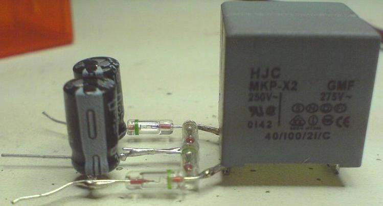 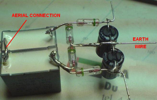 Now, consider this circuit as described, to be one modular building block which can lead to unlimited power from an aerial. I will represent the circuit shown above as a rectangle, showing the above circuit as:  While it is possible to use more than one module with the aerial to get more power, the Danish developer then switched to the full-blown Tesla arrangement by attaching a 800 x 600 x 2 mm aluminium plate inside the sloping roof of his house: 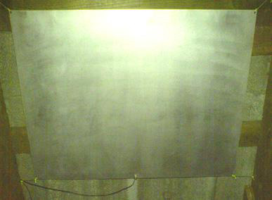 The plate being suspended using nylon cord to prevent it touching the roof or anything else: 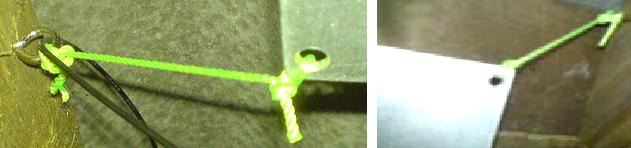 The plate is positioned between 3 and 3.5 metres (10 to 12 feet) above the ground and the attachment to the plate is also heavy-duty 8 swg cable: 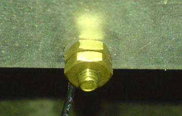 The cable is connected to the aluminium plate using a brass bolt and nuts which the builder thinks may be significant, quite apart from avoiding any galvanitic connection to the circuit. The cable is then run vertically downwards to the circuit. For this arrangement a second earthing point is also used. This is a galvanised iron pipe 3 metres long, driven vertically into the ground which is saturated with water. The second earth is 2 metres away from the first earth. This arrangement provides serious power, enough to cause injury to, or kill a careless human. With two modules, it will light an LED very brightly, driving it to 2.6 volts. If the LED is removed, then the voltage climbs to about twenty volts and is easily sufficient to charge a 12V battery or battery bank although that takes time. With twenty modules as 12V battery can be charged over night. It is estimated that with two hundred modules, the power would be sufficient to power a household although that has not yet been done. It should be borne in mind that each module is easy and cheap to make, so arranging for a stack of them where additional modules can be added at a later date for more power, is an ideal arrangement. The circuit is like this:  This circuit looks completely mad as the aerial input to the circuit appears to be directly short-circuited by the second earth connection. In spite of this, the circuit works very well when connected this way. Additional modules can be added without any known limit. Increased power can be had by either raising the aluminium plate higher above the ground, to say, 10 metres (33 feet), or by adding one or more additional aerial plates. As you have a good aerial connected through to a very good earth, there has to be the possibility of the equipment being hit by lightning, and so it is suggested that a protective spark-gap is installed between the aerial and the earth, close to the circuit, so that if high-voltage is suddenly applied to the aerial, the spark gap will fire and shunt the excess power through to the earth. Alternatively, possibly a better solution is to install a standard lightning rod system a few metres away from the aerial and a metre or two higher up, so that it forms a more attractive point for a lightning strike. Further experimentation has shown that altering the connection point for the aerial has a significant effect on the results. If the connection is made at the mid point between the aerial plate and the earth connection, it produces a greater output:  With this arrangement a single module produces around 30 volts while the original method of connecting near the earth was giving about 26 volts with two modules. Jes Ascanius has carried out further experimentation and he states that diodes with response times under 30 milliseconds produce a greater output and he recommends the use of BYV27 diodes which have a 200-volt 25nS rating as he gets three times the output from them. He also recommends using them in Joule Thief circuits. Dragan Kljajic has been experimenting with this circuit and has started by building many of these modules on a printed circuit board like this:   Using two of these boards, Dragan is pulling 96 watts continuously from his aerial plate. He intends to extend this arrangement much further, but is being hindered at present by a local civil war. Here is a forum where some builders of this system share comments. One comment is that there is an increased risk of a lightning strike where you have an earthed aerial, and so it is advisable not to place the aerial plate inside a house, but perhaps suspended between two trees. Also, using a car spark plug connected across the module set can protect against lightning strikes damaging the circuitry. As a result of queries, Jes stresses the following points: 1. The plate must be high off the ground. 2. The plate must be polished and insulated. 3. The wire must be single-strand solid wire. 4. There must not be any part of the wire above the circuit, which is not insulated. He further comments: you can use aluminium foil and cling film to make many collector plates 0.4 m x 5 m and connect them close together to feed the aerial wire. Remember, no uninsulated wire anywhere. Any queries should be asked on the forum shown above. A modification of this circuit of Jes Ascanius by a developer who prefers to remain anonymous, doubles the output of each module by adding a mirror image of the circuit like this:  As can be seen, the addition is of four diodes and two ceramic capacitors. Thomas Henry Moray In this field, Thomas Henry Moray is outstanding. By 1936 he had developed a piece of apparatus which was capable of putting out high power with no human-generated input power at all.  Moray’s equipment is said to have contained a germanium diode which he built himself in the days before solid-state devices became readily available. The equipment was examined and tested many times. On dozens of occasions, he demonstrated the equipment driving a bank of twenty 150W bulbs, plus a 600W heater, plus a 575W iron (a total of 4.175 kW). The power picked up by this device needed only small diameter wires and had characteristics different from conventional electricity. One demonstration which was repeated many times, was to show that the output power circuit could be broken and a sheet of ordinary glass placed between the severed ends of the wire, without disrupting the supply. This type of power is called “Cold electricity” because thin wires carrying major power loads, do not overheat. This form of energy is said to flow in waves which surround the wires of a circuit and not actually through the wires at all. Unlike conventional electricity, it does not use electrons for transmission and that is why it can continue through a sheet of glass which would stop conventional electricity dead in its tracks. On one occasion, Moray took his equipment away from all urban areas to a place chosen at random by a critic. He then set up the equipment and demonstrated the power output, well away from any man-generated electrical induction. He disconnected the aerial and showed that the power output stopped immediately. He connected the aerial again to generate the output as before. He then disconnected the earth connection which stopped the output again. When the earth wire was connected again, the output power returned. He found that the power output level fell somewhat at night. The aerial used in his demonstrations was reported to be like this:  From which it can be seen that even a relatively short aerial wire suspended not far from the ground, is capable of collecting substantial amounts of usable electrical power. The earth used in the remote demonstrations was a length of gas pipe which was hammered into the ground. It was noted that as each hammer blow drove the pipe deeper into the earth, the light bulbs (which formed the electrical load) shone more brightly, indicating that the quality of the earth connection is very important when serious power is being drawn from an aerial.  He developed various versions of the device, the latest of which did not need the aerial or earth connections, weighed 50 pounds and had an output of 50 kilowatts. This device was tested in both an aeroplane and a submarine, thus showing the device to be fully self-contained and portable. It was also tested in locations which were fully shielded from electromagnetic radiation. With his later devices, Moray leaves the area of aerials and moves into the same category as Barbosa and Leal, those two Brazilian men extracting 192 kilowatts of power directly from the ground. If you read Moray’s book “The Sea of Energy in which the Earth Floats” (The Sea of Energy in which the Earth Floats) you will discover that Moray moved past the scientific thinking of his day, stating that the Earth is being bombarded with cosmic energy particles which cause atoms to change from matter into energy, enter the aether and there revert to matter again. This process is governed by frequency. Moray developed energy diodes which act like electrical diodes on the energy flow of the aether. He used a chain of these ‘tubes’. Each tube was tuned to one of the harmonics of the oscillating frequency of the aether. Each tube produced lower frequency waves and the following tube is tuned to those waves and is driven by a resonant harmonic of the aether oscillations, thus producing a device with no need of any power input from the user. Also, the aerial was replaced by a small, internal copper plate. So in true aerial mode – four kilowatts. In earth-only mode – 50 kilowatts. Moray’s ideas are supported by the work and books by Gustav Le Bon (The Evolution of Matter and The Evolution of Forces). Moray was shot and wounded in an assassination attempt in his laboratory. This caused him to change the glass in his car to bullet-proof glass. He was threatened many times. His demonstration equipment was smashed with a hammer. When threats were made against his family, he stopped rebuilding his equipment and appeared to have turned his attentions to other things, producing a device for ‘therapeutic’ medical treatment. In his book “The Energy Machine of T. Henry Moray”, Moray B. King provides more information on this system. He states that Moray was refused a patent on the grounds that the examiner couldn’t see how the device could output so much power when the valve cathodes were not heated. Moray was granted US Patent 2,460,707 on 1st February 1949 for an Electrotherapeutic Apparatus, in which he included the specification for the three valves used in his power device, apparently because he wanted them to be covered by a patent. As far as can be seen, the valve shown here is an oscillator tube. Moray claimed that this tube had the very high capacitance of 1 Farad when running at its resonant frequency. Moray liked to use powdered quartz as a dielectric in the capacitors which he made, and he had a habit of mixing in radium salts and uranium ores with the quartz. These materials may well be important in producing ionisation in these tubes and that ionisation may well be important in tapping the energy field.  The tube shown above has a six-layer capacitor formed from two U-shaped circular metal rings with the space between them filled with a dielectric material. The plates are shown in red and blue, while the dielectric is shown in green. Inside the capacitor, there is a separate ring of dielectric material (possibly made from a different material) and an inside ring of corrugated metal to form an ion brush-discharge electrode. The capacitor and electrode connections are taken to pins in the base of the tube. Quartz is suggested for the material of the outer covering of the tube and the wire element numbered 79 in the diagram is said to be a heating element intended to be powered by a low-voltage current source. However, as Moray had an earlier patent application refused on the grounds that there was no heating element in his tubes, it is distinctly possible that the heating element shown here is spurious, and drawn solely to avoid rejection by the examiners. In his patent, Moray refers to the capacitor in this tube as a “sparking” capacitor, so he may have been driving it with excessively high voltages which caused repeated breakdown of the capacitor material.  The tube of Fig.16 above, uses a different technique where an X-ray tube is used to bombard a corrugated electrode through a screen containing an X-ray window. It is thought that a brief burst of X-rays was used to trigger very short, sharp bursts of ions between the anode and cathode of the tube and these pick up extra energy with every burst. An alternative version of this tube is shown in Fig.18 below. Here the construction is rather similar but instead of an X-ray window, a lens and reflector are used to cause the ionisation of the switching channel between the anode and cathode. In both tubes, the corrugated electrode supports a corona build-up just prior to the short X-ray switching pulse, and it is thought that the ions contribute to the intensity of the resulting pulses which emerge from the tube. Very short uni-directional pulses are capable of causing conditions under which additional energy can be picked up. From where does this extra energy come? In 1873, James Clerk Maxwell published his “Treatise on Electricity and Magnetism” and in it he pointed out that the vacuum contains a considerable amount of energy (Vol. 2, p. 472 and 473). John Archibald Wheeler of Princeton University, a leading physicist who worked on the US atomic bomb project, has calculated the flux density of the vacuum. Applying Einstein’s E=mC2 formula indicates that there is enough energy in every 1 cc of “empty” space, to create all of the matter in the visible universe which can be seen with our most powerful telescopes. That amount of energy is so great as to be beyond imagining. This energy field is referred to as “Universal Energy”, “Cosmic Energy” or “Zero Point Energy”. At this time, we do not have any instrument which responds directly to this energy and so it is almost impossible to measure. The existence of this energy field is now widely accepted by mainstream science and it is borne out by the situation found at quantum levels. It is generally thought that this energy is chaotic in form and for useful energy to by drawn from it, it needs to be restructured into a coherent form. It appears that uni-directional electromagnetic pulses of one millisecond or less, can be used to cause the necessary restructuring as they generate an outward coherent wave of radiant energy, from which energy can be extracted for use in most electrical devices, if a suitable receptor system is used. Tom Bearden states that at the quantum level, the seething energy of this field appears continuously as positive and negative charges. As these are evenly distributed, the net charge at any point is always zero. If a “dipole” (two opposite charges near each other) is created anywhere, then it polarises the energy field disrupting the previously even distribution of charges and causing massive streams of energy to radiate outwards from the dipole. A voltage pulse acts as a dipole, provided the voltage rise is fast enough, and that is what causes a wave of radiant energy fanning out from the location of the voltage pulse. Batteries and magnets create continuous dipoles and so cause the local quantum energy field to send out continuous streams of massive power which can be utilised if (and only if) you know how to do it. The search for mechanisms to capture and use even a tiny fraction of these energy streams is what the “free-energy” field of research is all about. Some people say that there is no such thing as “free-energy” because you have to pay for the device which captures it. That is like taking a bus trip to a car dealership where they are giving away new cars, and saying that your new car was not a “free” car because you had to pay a bus fare to reach the car dealership.  Moray King suggests that the circuit used by Thomas Henry Moray was as follows:  There can be little doubt that Thomas Henry Moray built several versions of his apparatus, each of which produced output power well in excess of any input power needed. It seems highly likely that most of them used no input power whatsoever, and if there were any others, they will have been powered by a tiny fraction of the output power. If mild radioactive material was used as described, then the output power could in no way be attributed to that source alone, since the output power was thousands of time greater than any power available from the radioactive materials. It is perhaps time to explain a little more about, voltage, power and current. We have been raised with the notion that it is necessary to “burn” a fuel to get power, that batteries “run down” when used and that you have to keep turning the shaft of an electrical generator to be able to draw current from it. These things are not actually true. The relatively recent field of Quantum Mechanics shows that if a charge, such as an electron has, is positioned in what is supposed to be “empty” space, it is not alone. The “empty” space is actually seething with energy, to the extent that “virtual” particles are popping into existence for a fraction of a second and then disappearing again. They are called “virtual” because they exist for such a short time. Because of the negative charge of the electron, the particles appearing and disappearing around it will all be positive in charge. The electron has “polarised” the space around itself because it has a charge. The instant that a positive “virtual” particle appears, there are two charges near each other - minus on the electron and plus on the particle. When you have two opposite charges near each other, they form a “dipole”. Dipoles form a gateway through which energy from the environment flows continuously. An instant later, the particle disappears, but it’s place is immediately taken by another virtual particle. The result is a continuous stream of energy flowing out from the dipole. Batteries with their positive and negative terminals are electrical dipoles, so too are generators when the input shaft is spun. Permanent magnets with their North and South poles are magnetic dipoles. Both of these have continuous streams of energy flowing through them. So, why then do batteries run down and lose their charge? The reason is that we power circuits using a closed loop. The energy flowing out of one terminal flows into the opposite terminal and instantly destroys the dipole. A new dipole has to be created every split second if the circuit is to deliver power, and it is that self-destructive method of use which causes the battery to discharge or which needs the generator shaft to be rotated continuously. If a different operating technique is used, where the dipole is not continuously destroyed, then devices which can provide a continuous stream of energy drawn from our natural environment can be constructed. This is not magic, just the next step in conventional science and engineering. Thomas Henry Moray managed it, initially with an aerial and earth like a crystal set to provide the dipole, his device was able to draw many kilowatts of power from the environment. No fuel was needed, the energy is already there surrounding us all, all of the time. As far as I am aware, nobody has managed to replicate Moray’s device (which was the reason for it being violently suppressed) but knowing that it existed and was repeatedly demonstrated to work perfectly well, is useful in that it shows that it is possible to tap the massive zero-point energy field with a practical, home-constructed device. Here is a collection of additional items of information gathered from several different sources: Moray started his experiments with 'the taking of electricity from the ground', as he described it, during the summer of 1909. By autumn 1910 he had sufficient power to operate a small electrical device, and demonstrated his idea to two friends. The early stages of this demonstration consisted of operating a miniature arc light. It soon became clear to him that the energy was not static and that the static of the universe would be of no assistance to him in obtaining the power for which he was searching. During the Christmas Holidays of 1911, he began to realise fully, that the energy with which he was working, was of an oscillating nature. He also realised that the energy was not coming out of the earth, but instead, was coming to the earth from some outside source. These electrical oscillations in the form of waves were not simple oscillations, but were surging like the waves of the sea, coming continually to the earth but more in the daytime than at night, but always arriving as vibrations from the reservoir of colossal energy out there in space. By this time Moray was able to gather enough power to light a 16-candlepower carbon lamp to about a half of it's capacity, but he did not manage to gain any further improvement until the spring of 1925. In 1912 Moray was called to go on a mission for the Church of Jesus Christ of Latter-Day Saints, and under a visitor's visa was allowed to enter Sweden during the Exhibition of 1912 in Stockholm. In his notebook, dated November 1, 1913, he included a note saying that he had obtained material from a railroad car at Abisco, Sweden the previous summer, also some more material from the side of a hill. He made electric tests of these materials, taking them home to try each as a detector for his energy machine. Tests indicated that this soft, white stone-like substance might make a good "valve-like detector". This "valve-like detector" is what led him to do research into semi-conductive materials, and from this soft white stone he developed his first valve and the valve which was used in some of his early Radiant Energy devices (silver wire touching a stone can act as a rectifier). Moray demonstrated that energy was available by its actions on a resistive load, such as a flat-iron or a space heater, and by lighting bulbs. A resistive device acts as a load which is directly proportional to the amount of energy delivered to it. In heating a heater, or lighting a bulb, the number of watts produced can be calculated as equal to the number of watts provided to the device. This energy is fed into a load to give either heat, light, or power. A motor can be operated but it must be designed to run on a high frequency power supply. The Radiant Energy device used an antenna and a ground connected to his solid state Radiant Energy circuit:  The diagram shown above is reproduced from a rough sketch drawn from memory after seeing Moray's circuit diagram. The person who drew it does not understand how the circuit works, so please treat this diagram as being just an overall suggestion as to what Moray's circuit might have been like. It is actually much more likely that is was a cascade of pairs of tank circuits containing Moray's valve, each pair being one series tank circuit followed by one parallel tank circuit, the oscillating frequency dropping with each tank pair and the output power rising with each tank pair. Moray's circuit was started oscillating by stroking the U-shaped coil with a permanent magnet for a few seconds, and when the circuit started operating, then switch 'S' was closed, effectively removing the U-shaped coil from the circuit. Moray was able to demonstrate that none of the output energy came from within his device. Internally the device was electrically dead when it had not been connected and tuned to the antenna. When his device was set up, he could connect it to an antenna and ground, and by priming it first and then tuning it as he primed it, the device would draw in electrical energy. This high frequency electrical energy produced up to 250,000 volts and it powered a brighter light than witnesses had ever seen before. Heavy loads could be connected to the device without dimming the lights already connected to it. This device worked many miles from any known source of electrical energy such as power transmission lines or radio signals. The device produced up to 50,000 watts of power and worked for long periods of time. Moray initially assumed that this energy was electromagnetic in nature however, he never claimed that it was. He assumed at first that this energy came from the earth but later he believed it was flowing in from the universe. Finally he began to believe that it was present throughout all space, intermolecular space as well as terrestrial and celestial space. He did not necessarily understand how his detectors operated, only that if he built the device very carefully according to his calculations it would work. He was able to demonstrate the existence of an energy that today, though it has not been identified or proven, has been theorised by many researchers. The largest instrument was about 6 inches high, circular in shape and about 8 inches in diameter. We went out on the roof of the chicken coop carrying the device on a small drafting board, erected an antenna upon the roof of the coop, the antenna being about 100 feet from the house. We pulled the main line switches in the house before going out upon the roof. Mr Judd had Moray move the drafting board from place to place and he also examined the inside of the coop for hidden equipment. The machine was then assembled in his presence and the device was started. Mr Judd timed me to see how long it would take to bring get the light operating. I was able to light the CGE lamp to its full brightness and to heat an old-style Hotpoint electric flat iron to sizzling point, which required 655 watts. Mr Judd asked for the antenna to be disconnected. When this was done, the light went out. The aerial was connected again and the light reappeared. We drove a new grounding rod at a spot selected by Mr Judd, made a connection to the new grounding point and the light burned dim, but came brighter and brighter as the new grounding rod was driven deeper and deeper into the ground. If the ground or antenna is left disconnected for too long a time, the device becomes electrically dead and must be retuned in order to regain the energy flow. Dr Eyring found no fault with the demonstration and the worst that he could say about it was that it might be induction, but that if Moray would take the device out in the mountains away from all power lines, a distance of three or four miles, and it then operated, he would then acknowledge that it could not be induction and that his theory was wrong. At last they decided to go up Emigration Canyon, as there are no power lines in that canyon. All three gentlemen were very well satisfied and pleased with what they saw. The antenna wire was put up without any aid or instructions whatever from Mr Moray, except that he suggested that the wire be stretched tighter to prevent so much sag at the centre. This was done and the wire then appeared to clear the ground by about 7 or 8 feet at its lowest point. The ground pipe was of half-inch water pipe consisting of two sections. The lower section was pointed at the end to make its driving into the creek bed easy. It was about 6 feet long and after being driven down about 5 feet the second section, which was about 4 feet long, was screwed on with a wrench and the pipe driven further down until it struck a hard object, so about 7 feet of pipe was in the ground. The antenna wire was insulated from the poles with two glass insulators about 6 inches long and having holes in both ends. A piece of wire about 2 feet long connected each insulator with the pole. The lead-in wire was fastened to the antenna wire at a point about 10 or 15 feet from the east pole. I helped Mr Moray solder the connection. I paced the distance between the two antenna poles and estimated it to be 87 feet. Mr Moray's equipment, apart from the antenna and ground wires, consisted of a brown box about the size of a butter box, another slightly smaller unpainted box, a fibre board box about 6" x 4" x 4", which Mr Moray referred to as containing the tubes, and a metal baseboard about 14" x 4" x 1" containing what appeared to be a magnet at one end, a switch near the middle and a receptacle for an electric light bulb at the other end. There were also several posts for connecting wires on the baseboard. When all of the wires were connected and everything was ready, Mr Moray began tuning in. Before tuning, he placed the key on the post: he said it would be in contact while the light burnt, but no light appeared. The tuning consisted of stroking the end of a magnet across two metal projections protruding from what I referred to above as being 'a magnet'. After tuning for slightly more than 10 minutes the key was put on the operating post and the light appeared immediately. Mr Moray put the key on the operating post two or three times before during the tuning operation but no light appeared. We allowed the light to burn for 15 minutes. In my opinion, the brilliance of the light coming from the 100-watt bulb, was about 75% as bright as a 100-watt bulb connected to an ordinary house socket. It was an steady light, without fluctuations of any kind. While the light was burning Mr Moray disconnected the antenna lead-in wire from the apparatus and the light went out. He connected it again and the light appeared. He also disconnected the ground wire and the light went out. He then connected it and the light appeared again. In another demonstration, Mr Moray opened the device and let everyone see everything except one small part that he placed his hand over and hid in his fist. This part he cut off and put in his vest pocket. Everything else, people were allowed to examine to their hearts' content. "If that part is able to make such power itself, then it's some device and worth selling. Such a battery would be worthwhile", were some of the remarks made. On several occasions Dr Moray would disconnect the antenna wire momentarily, but not long enough to lose the light. In disconnecting and connecting the antenna wire a flash of electricity could always be seen at the At a demonstration in 1928, the aerial used was about 200 feet long and positioned about 80 feet above the ground: the wire is a copper cable approximately a quarter of an inch in diameter, and well insulated. The earth connection used was the water pipe in the basement of Dr Moray's home. The device was assembled in a trunk through the sides of which were holes for the connections to ground and to the antenna and for observation; the holes were about one-half inch in diameter. There were two boxes about 10 by 20 by 4 inches, one on top of the other; both were closed and the covers fastened with screws. On the upper box was lying an insulating panel about an inch thick by 15 inches long and 3 inches wide; it was made of slate or hard rubber or some material of similar appearance. On this were two binding posts which could be connected together by a small switch; also mounted on this panel was an object about 2.5 inches square, wrapped in friction tape, from which protrude two poles about 1/4-inch in diameter, apparently of sift iron. Two light bulb sockets were connected in the circuit. In one of these there was a 20-watt bulb, and in the other a 100 watt bulb. Dr Moray then took a magnet, which was a very broad, short limbed U, and began to stroke one pole of it on the poles in the taped body. Mr Jensen placed his fingers on the binding posts several times, and at last received a rather vigorous shock. Mr Moray then threw the switch and the bulbs lit up. As a further proof that the conversion of the energy was due to the mechanism in the box, Dr Moray hit the table on which the trunk was standing, a moderate blow with a hammer whereupon the light flickered and went off, due to the detector being shaken out of adjustment. The boxes, in which the mechanism had been housed during the test, were opened and the contents examined. There were capacitors, the detector, a transformer, and two tubes in them but nothing else. Nothing that in the least resembled a battery. It is to be noted that after a total run of 158 hours the device supplied 635 watts; inasmuch as a horsepower is but 746 watts this equals 0.878 of a horsepower or slightly more than 7/8 horsepower. This alone is sufficient to dispose of any suggestion of a battery. A report from 1929 says: It is now more than 2 years since I first became acquainted with Dr T. H. Moray and the work he is carrying on, and in that time he has demonstrated inventive ability of an exceptional order. Perhaps the most wonderful of his inventions is a device whereby he is able to draw electric power from an antenna. This energy is not derived by induction from power lines, as has been suggested by some, nor is it derived from radio stations, as has been demonstrated by taking the apparatus more than 26 miles from the nearest power line and over a hundred miles from the nearest radio station and showing that it operates just as well as anywhere else. This device was subjected to an endurance test in which it was operated continuously for a week, and at the end of that time a 100-watt lamp was lighted simultaneously with the heating of a 575 watt standard Hotpoint flat iron, making a total of 675 watts; it is very evident that no batteries could sustain such a drain as this. He has also invented a very sensitive sound detector whereby it is possible to hear conversations carried on in an ordinary tome of voice at a distance of several blocks. He has also worked out numerous radio hook-ups which eliminate many of the parts now considered necessary for good reception, yet there is no diminution in quality or volume; in fact, there is a notable elimination of interference from static when some of these are used. He has devised a means by which he is able to measure with some degree of accuracy the energy evolved during mental activity; that is, he gets definite, variable deflections of the needle of a sensitive galvanometer which appeared to be related to the vigour of mental activity. There are a great many other equally remarkable things which he has done, such as reducing old rubber from truck tires to the state of a viscous fluid which is readily vulcanisable without the addition of smoke sheet as is necessary with other processes; also a high frequency therapeutic device, and numerous other devices which show great ingenuity. The 6 lamps are set up in parallel and a small diameter wire is used as the current enters the tube prior to and connecting with the step-down transformer, this takes the very high voltage to the transformer. This voltage will jump across a spark gap of at least six inches. The operating frequency is so high that I have no instrument in my laboratory that is able to measure the amperage or the voltage at this frequency. (Signed, Murray O. Hayes, PhD.). Dr Milton Marshall was attempting to identify the material that Moray called his "Swedish Stone". Moray described the radio detector which he had developed. He compared it to what was commonly known as the crystal of a crystal set. However, his detector was superior since it could drive a loudspeaker without the use of a battery. He used the most easily demonstrated device, the germanium diode, that worked on the same principle to illustrate how he thought the Radiant Energy Detector worked (Moray originally built the radio simply for the purpose of showing how he was able to pick up radio signals with a solid-state device, producing sufficiently strong signals which could drive a loudspeaker, which was something unheard of in that day. His circuit did not have batteries, and it was very similar to the old crystal-set circuitry. The device was housed in a wooden box something like 12" by 18", with an antenna and a ground going into it. Wires leading out of the box led to a bank of some forty 100-watt light bulbs and to an electric iron. Moray touched a switch at the top of the box with a hand electrostatic plate and the globes all lit up brilliantly. We all noted that the bulbs burned cold except each had a hot spot about the size of a dime on the top slightly off centre. I also recall that I could turn the lights on and off by approaching and retreating to and from the device, either with my whole body or my hand. If my memory is clear, the machine had to be tuned with a dial to be placed in this condition. (Chester M. Todd, 1971) In 1938, after examining the transformer of the device, Mr E. G. Jensen stated that he considered that the amount of current which he had seen taken from the device was positive proof that the current developed by or in the machine was different to any in use at that time. This was because the transformer would have burned out if it had been carrying normal current, but the transformer showed no signs of even ever having been warm. He was informed by Dr Hayes that the transformer had been in use under the same loading conditions during many demonstrations in the past. The "Number 1" capacitor consisted of two small sheets of aluminium of about 30 gauge, separated by and making contact with a piece of one-quarter inch thick plate glass. The plate glass was larger than the aluminium sheets and overlapped them. The "Number 2" capacitor was a commercial unit manufactured by Igred Condenser & Mfg. Co. and had a capacity of 0.025 mfd. They were used as shown here:  With the 60 watt lamp and the two capacitors attached to the antenna and the antenna and ground attached to the box containing the Radiant Energy equipment as shown in the sketch, the 100-watt lamp on the secondary or output side was lighted. Unscrewing the 60-watt lamp from its socket caused the 100-watt amp to go out, but it immediately lighted when the 60-watt lamp was screwed into its socket again. The 60-watt lamp did not light. Shorting the antenna and ground by placing a wire across them, caused the 100-watt lamp to go out. Similar shorting with the hands also caused the 100-watt lamp to go out. No electricity could be felt when shorting with the hands. If either the ground or the antenna wires were disconnected from the box, the 100-watt lamp would go out. Neither of the capacitors or the 60-watt lamp on the primary side of the box were necessary but were simply put there to show that the high frequency power will jump or pass through them. Moray's patent application on this device was filed in 1931 and rejected on a number of grounds. Firstly, "Because no means was provided for causing the cathode to emit an appreciable number of electrons, the current produced in the cathode by the antenna will not heat the cathode to a temperature at which an appreciable number of electrons per second are emitted". In other words, according to Thomas E. Robinson, Commissioner of Patents, a solid state device, such as a transistor, cannot possible work. Secondly, because "No natural source of electric wave energy is known to the Examiner and proof of the existence of such a source is required". In other words, it was not enough for Moray to demonstrate the effect of the energy source; he also had to identify it, which he could not do. None of the original patent applications that Henry made are any longer available at the US Patent Office. Although their file jackets are there, the contents and applications themselves are gone. In 1942, Moray attempted to rebuild a Radiant Energy device, using the remaining bit of what was known as the "Swedish Stone". This material, which was the heart of his original RE detector, he had never managed to duplicate, and the shortage of this material limited the amount of power which he could draw. Consequently, in the large unit, he developed a second detector that forced him into extensive research involving nuclear materials and radioactive reactions. He became deeply involved in the study of synthetic radioactivity as described by Gustave LeBon in his book "The Evolution of Matter". The years slipped by and Moray spent most of his time working on what he called the "counter-balance" to eliminate the need for an aerial antenna. Moray said: Enough energy is coming to the earth to light over 1,693,600 100-watt lamps for every human being on the earth today. No fuel of any kind need be taken as this energy can be picked-up directly by ocean liners, railroads, airplanes, automobiles, or any form of transportation. Heat, light and power can be made available for use in all kinds of buildings and for all kinds of machinery. An example would be to pump water onto the desert lands, the power source being only a fraction of the weight of any steam plant or any kind of engine in use today and all this at a fraction of the current cost. The total energy involved in "cosmic" radiations is very large. The mechanism of its generation involves a basic relationship with the total structure and action of the universe. Today it is believed that cosmic radiation consists primarily of protons and some heavier nuclei. At times this cosmic energy packs a wallop of around 100 quadrillion volts. Coming continuously with slight variations in time, the radiations have a uniformly directional isotropy. The earth is, therefore, surrounded in an atmosphere of radiation with cosmic rays coming continually to the earth from all directions, although there may be a slight deflection of the weaker rays by the earth's magnetic field. There is every indication that our sun is not the source of any appreciable amount of this radiation. The origin, therefore, is from the universe as a whole. The total energy of cosmic radiation is more than the entire luminous output of all the stars and nebulae of the universe combined. Unlimited power is being delivered to everyone's doorstep. The Moray Radiant Energy discovery, using radiations from the cosmos as its power source, gives the greatest amount of energy per pound of equipment of any system known to man. Electrical power through an electric motor or an electric jet far exceeds any form of energy in any engine in the delivery of power. There is no dead centre of lost motion in an electric motor nor loss of push in an electric jet. Also, the starting torque is much higher in the electrically powered engine than in the combustion engine. Harnessing cosmic energy is the most practical method yet discovered by man. Furthermore, it is possible to utilise this vast source of energy from the universe without a prime mover at any point on the earth --- on the ground, in the air, on the water, under the water, or even underground. If one considers that an electrical generator is not in the true sense a generator - as electricity is not made by the generator - but is merely an electrical pump, the Moray Radiant Energy device may then be referred to as a cosmic ray pump: that is, a high speed electron oscillator serving as a detector of cosmic radiations which causes a pumping action or surging within its circuitry. To account for the propagation of heat and light - two of the forms of Radiant Energy - man has postulated the existence of a medium filling all space. But, the transference of the energy of radiant heat and light is not the only evidence in favour of the existence of such a medium. Electric, magnetic, and electromagnetic phenomena and gravitation itself point in the same direction. Attractions and repulsion take place between electrified bodies, magnets, and circuits conveying electric currents. Large masses may be set in motion in this manner, acquiring kinetic energy. If an electric current is started in any circuit, corresponding induced currents spring up in all very closely neighbouring conductors. To originate a current in any conductor requires the expenditure of energy. How, then, is the energy propagated from the circuit to the conductors? If we believe in the continuity of the propagation of energy - that is, is we believe that when it disappears at one place and reappears at another it must have passed through the intervening space and, therefore, have existed there somehow in the meantime - we are forced to postulate a vehicle for its conveyance form place to place. When a particle is electrified, what one must first observe is that a certain amount of energy has been spent; work has been done. The result is an electrified state of the particle. The process of electrifying a conductor is, therefore, the storing of energy in some way in or around the conductor in some medium. The work is spent in altering the state of the medium, and when the particle is discharged, the medium returns to its original state, and the store of energy is disengaged. Similarly, a supply of energy is required to maintain an electric current, and the phenomenon arising from the current are manifestations of the presence of this energy in the medium around the circuit. It used to be that an electrified particle or body was supposed to have something called "electricity" residing upon it which caused electrical phenomena. An electric current was regarded as a flow of electricity travelling along a wire (for example), and the energy which appeared at any part of a circuit (if considered at all) was supposed to have been conveyed along the wire by the current. But, the existence of induction and electromagnetic interactions between bodies situated at a distance from each other leads one to look upon the medium around the conductors as playing a very important part in the development of these electrical phenomena. In fact, it is the storehouse of the energy. It is upon this basis that Maxwell founded his theory of electricity and magnetism, and determined the distribution of the energy in the various parts of an electric field in terms of electric and magnetic forces. The medium around an electrified body is charged with energy and not of an imaginary electric fluid distributed over the electrified body or conductor. When we speak of the charge of an electrified conductor we are referring to the charge of energy in the medium around it, and when we talk of the electric flow or current in the circuit we are referring to the only flow we know of, namely, the flow of energy through the electric field within the wire. The work in producing the electrification of a conductor is spent on the medium and stored there, probably as energy of motion. To denote this we shall say that the medium around the conductor is polarised, this word being employed to denote that its state or some of its properties have been altered in some manner and to a certain extent depending on the intensity of the charge. If the charge is negative the polarisation is in the opposite sense, the two being related, perhaps, like right-handed and left-handed twists or rotations. Now consider the case of a body charged alternately, positively and negatively in rapid succession. The positive charge means a positive polarisation of the medium, which begins at the conductor and travels out through space. When the body is discharged the medium is once more set free and resumes its former condition. The negative charge now induces a modification of the medium or polarisation in the opposite sense. The result of alternate charges of opposite sign is that the medium at any point becomes polarised alternately in opposite directions, while waves of opposite polarisations are propagated through space, each carrying energy derived from the source or agent supplying the electrification. Here, then, we have a periodic disturbance of some king occurring at each point, accompanied by waves of energy travelling outwards from the conductor. The phenomenon of interference leads to the conclusion that light is the result of periodic disturbances or vibrations of the medium, but as to the nature of these vibrations, as to the exact nature of the periodic changes or what it is that changes them, we possess no knowledge. We know that alternating electric charges are accompanied by corresponding changes of state or vibrations of the medium, and if the charge is varied periodically and with sufficient rapidity, we have a vibration at each point analogous to, perhaps identical with, that which occurs in the propagation of light - a combination of wave and particle properties. This then is the electromagnetic theory of the luminous vibration. In the older elastic-solid theory, the light vibrations were supposed to be actual oscillations of the elements or molecules of the medium about their positions of rest, such as takes place when waves of transverse disturbance are propagated through an elastic solid. Such limitation is unwarranted to some extent, but one cannot afford to entirely disregard the particle theory of light either. A combination of the theories has merit. We know that the change, disturbance, vibration, polarisation, or whatever we wish to term it, is periodic and transverse to the direction of propagation. The electromagnetic theory teaches us nothing further as to its nature, but rather asserts that whatever the charge may be, it is the same in kind as that which occurs in the medium when the charge of an electrified body is altered or reversed. It reduces light and heat waves to the same category as waves of electrical polarisation. The only quality of the later required to constitute the former is sufficient rapidity of alteration. These speculations were given the strongest confirmation by experiments of Prof. Hertz many years ago. When a resilient substance is subjected to strain and then set free, one of two things may happen. The substance may slowly recover from the strain and gradually attain its natural state, or the elastic recoil may carry it past its position of equilibrium and cause it to execute a series of oscillations. Something of the same sort may also occur when an electrified capacitor is discharged. In ordinary language, there may be a continuous flow of electricity in one direction until the discharge is completed, or an oscillating discharge may occur. That is, the first flow may be succeeded by a backrush, as if the first discharge had overrun itself and something like recoil had set in. The capacitor thus becomes more or less charged again in the opposite sense, and a second discharge occurs, accompanied by a second backrush, the oscillation going on until all the energy is either completely radiated or used up in heating the conductors or performing other work. When capacitors are filled with energy captured by the Moray Radiant Energy device and then discharged through a circuit of proper impedance, reactance and inductance, thereby synchronising the oscillation of the device with those of the universe, electrical inertia is set up. In the reversal of the current, the capacitors are charged, discharged and recharged slowly until the energy stored in them is radiated in kinetic energy through the device, and this energy can be kept alive indefinitely by establishing resonance with the oscillations of the universe. Considering oscillations from a mechanical, electrical and mathematical point of view, we find that electrical resistance is the same as mechanical friction and current is comparable to mechanical velocity. Inertia and inductance may then be considered analogous terms. In mechanics the greater the inertia of a body, the longer it will stay in motion. In the Radiant Energy device's resistance-inductance-capacity (REC or RLC) circuit, the greater the electrical inductance, the longer the current continues to flow once it is established by synchronisation with cosmic surges. Expressed mathematically, the equations are the same for electrical or mechanical phenomena. Which means, that R < square root(4L / C), where R is the resistance in ohms, L is the inductance in henries, and C is the capacitance in farads. When this is true, an oscillatory discharge will occur and a very powerful inductance inertia will assert itself. For low values of R, the frequency of the oscillations can be shown by f = 1/2 x pi x square root(CL). The rapidity of the oscillations is governed by the capacitance and inductance. In the vibrational forces of the universe, we find the key to the source of all energy. How we can utilise this energy for modern industry without being limited to mechanical prime movers is the question. And, the answer may be an energy generator, balanced so as to oscillate in synchronisation with the oscillations of the universe. Dr Ross Gunn, a civilian scientist for the US Navy, stated years ago that the earth is a huge generator, generating over 200 million amperes of electric current continuously. For example, the aurora borealis is considered to be a very large definite electrical phenomenon produced by the passage of electric charges through the rarefied gases of the higher atmosphere. The earth has since been shown, by Dr Gunn and others, to have a negative charge amounting to 400,000 coulombs. Yet, six feet above the ground the air is charged with more than +200 volts with respect to the ground. It is known that air conducts electricity away from charged objects. This being true, how does the earth maintain its charge since it is a charged object exposed to the surrounding atmosphere? If the air conducts electricity, the earth's charge must be constantly passing into the atmosphere. And it has been calculated that the earth has a continuous discharge into the atmosphere of 1,800 amperes. At this rate, the earth should lose 90% of its charge into the air in one hour, yet the earth's charge does not diminish. From where does the earth's energy come? The conversion of matter to energy in the stars is accepted, and, reasoning from what occurs in radioactive disintegration during which energy waves are radiated, one may conclude that energy waves of very high frequency are sent out from the stars (one of which is our sun). Now, of course, the conversion of energy into matter must equally be accepted. It has been found that ionisation, which could be the medium for the flow of energy, increases with increasing altitude, instead of decreasing as would be expected. Since the source of energy is the universe, the generation of energy by rotary action and by all prime movers is an effect and not a cause. Oscillatory energy action, be it in a Leyden jar, another man-made capacitor, or in what we may call natural capacitors, always behaves the same. The oscillations will continue until they have reach their cycle of height and then there will be a backrush returning to where the oscillations originated. Every oscillation, whether large or small, is completed during the same interval of time. These oscillations all prove the same great fact, that they are governed by the same cycle of time, completed during the same interval of time. Waves of energy have a regular beat note, coming and going as the waves of the sea, but in a very definite mathematical order - coming to the earth from every direction with a definite rhythm. Energy has a definite elastic or resilient rigidity and density, which is subject to displacement and strain. When strain is removed, the medium will spring back to its old position and beyond, surging back and forth, and will continue to oscillate until the original pressure is used up. If the internal impedance is too great, there will be no oscillations, but it will merely slide back in a dead beat to its unrestrained state. By cutting down resistance to a minimum and synchronising the resilient ionic actions of the Moray device with the wave actions of the universe, periods of oscillation can be made to come quicker and quicker until inertia asserts itself, thus lengthening out the time of final recovery. This is done by carrying the recoil beyond the natural oscillations and prolonging the vibrations by capturing the in oscillatory action. When the recovery becomes distinctly oscillatory, a harmonic pattern is initiated and the oscillations continue, resonance thereby being established with the universe. In the universe we see the same laws being obeyed as in our laboratories. As one traces down to the almost infinitesimal constituents of the atom, one finds that matter does not exist at all as the realistic substance which we have supposed it to be. There at the very foundation, it consists of nothing more than energy charges emitted at various wavelengths or frequencies. It is becoming more and more certain that the apparent complexity of nature is due to our lack of knowledge. And, as the picture unfolds, it promises a marvellous simplicity. One of the most marvellous relationships that has ever been revealed in the entire science of physics is that between light and electricity and the existence of electronics in atoms of matter. Knowing what we do at the present time with regard to the structure of atoms, this relationship is not quite so surprising. However, considering the total absence of this knowledge about a half century ago, the discovery that light, and radiation in general, are vibratory phenomena was revolutionary. Speaking of radiation, "Radiant" here means proceeding from a centre in straight lines in every direction. Energy is internal and inherent. "Energy" is defined as a condition of matter, by virtue of which, any definite portion may affect changes in any other definite portion. This was written in 1892, and discoveries since confirm it. Energy then is a state of matter, or rather, the result of a particular state or condition in which matter may be when any observed phase of energy appears. In addition to possessing kinetic energy, the atom is capable of absorbing energy internally. This internal energy is associated with the configuration of the particles of which the atom is composed. Under ordinary conditions an atom is in what is known as a state of equilibrium, in which there is neither a giving off, nor an absorbing of energy. But, the internal energy of the atom can be altered. When the internal energy of the atom exceeds that of its normal state it is said to be excited. Excitations may be caused in several ways, e.g., the collision of an atom with rapidly moving positive or negative particles or the breaking of lines of force in an electromagnetic generator. Kinetic energy is released when excitation causes a particle to give up some or all of its kinetic energy to the atom during collisions. This is taking place in the universe all the time. The electric motor and generator would never have been discovered if a dielectric (insulator) had not been discovered. If one discovers a dielectric valve for the energy of the universe, one has the answer to harnessing the energy of the universe! A limiting case of excitation is ionisation, wherein energy is absorbed by the atom sufficiently to allow a loosely bound electron to leave the atom, against the electrostatic forces which tend to hold it within the atom. An atom which has given up one or more electrons is said to be ionised. It is possible that ionisation, i.e., excitation, may take place in successive steps through absorption of quanta energy. The return of an ionised atom to a state of lower energy is associated with electromagnetic radiation. Also, from the process of ionisation, electrical energy may become associated with the vibrational forces of the universe coming into the earth as cosmic radiation. The higher the frequency, the greater the ionisation or excitation, a form of energy which is kinetic in nature. There are tremendous energies coming to the earth from outer space. These energies are only different manifestations of the energies we see in operation all around us. In most cases we are not even aware of their existence. They penetrate everything including our own bodies. Every one of us is alive by virtue of these energies. Every part and particle of the universe is alive with them. The generators that now furnish our electric power do not create or originate any power or electricity; they merely direct, pump, the existing energy or electricity. As in musical notes of high and low "C", the vibrational rates (frequencies) are different, but all "C" notes are essentially the same (harmonically related). This is the foundation upon which much of my investigation of vibratory phenomena is based. It has been agreed that all forms of matter are vibrating at a particular rate or frequency. And, so it is with the various forms of energy - heat and light, magnetism and electricity. These are but forms of vibratory motion connected with and being generated from the same source, the universe. Matter vibrates at a particular rate, according to its character, and may be transmitted into other substance by lowering or raising its rate of frequency. If the frequency is raised high enough, the molecules will separate and the atoms become free. Raising the frequency still higher, the atoms resolve themselves into their original components. Matter then becomes a form of energy. Frequencies may be developed which will balance the force of gravity to a point of neutralisation. One can then go beyond the force of gravitation. Understanding the principles of vibration is truly understanding energy. In gamma rays, we find potentials which are equivalent to as much as 1,000,000 volts, yet their wave lengths are not the shortest known. In octaves still higher there are rays which are known as "cosmic rays". Who can draw a definite line and say how much higher other octaves exist than those knows as the cosmic rays? Our starting point from the discovery of these different waves was electrical conductivity of the air, and it has been found that this conductivity is just as strong by night as by day. Radiations emitted by the sun can scarcely be the sole cause of this energy. All space is saturated with vibration, energies, which are no doubt electrical in character. The relation of matte to energy and energy to matter then becomes the potential of the universe - one continuous series of oscillations. Atoms maintain an equilibrium by oscillations, rotations, attractions and repulsions, but this does not interfere with a transformation of equilibrium, which, when the transformations of equilibrium are rapid enough, become energy, i.e., matter is turning into energy and energy into matter. There can be no generation of electrical current and no kinetic energy if there is no disturbance of equilibrium, i.e., change of potential or change of energy levels. When one thinks of the oxygen and nitrogen molecules of the air all about us moving with the speed of bullets and striking us and everything else at this speed, one can form some idea of the agitation taking place here and in the universe. The oscillations from outer space are emitting electromagnetic waves of many wavelengths and frequencies. The Moray device is so constructed that the frequency is very much lower on the secondary side than on the primary side, and almost complete resonance is established. I am convinced that the energies from the universe are active radiations produced by the evolution of matter into energy and energy into matter. Dr Anderson's cloud chamber at the California Institute of Technology, in which the positron was discovered, has furnished much information about cosmic ray energies. He found that some positrons are born of cosmic rays smashing into matter. The cosmic ray energies deduced from the tracks left in the Anderson cloud chamber range from 100 volts to 3,000,000,000 volts. The Lemaitre-Vallarts theory, together with Dr Johnson's asymmetry measurements, give definite values for the energy of half of the cosmic radiation, and shows it continuously distributed between 5 billion and 50 billion volts. The figure of 100 billion volts is a result of Dr W. Kolhorster's measurement of penetrating radiation in the depths of the Strassfurt salt mines. He found that the minimum energy of these rays had a penetration which was greater than ever before demonstrated. Dr Axel Corlin of Sweden's Lund Observatory found radiation that still had energy after passing through somewhat greater depths and, therefore, the voltage figures can be made even higher. Energies of 100 billion volts or more are indicated by the great bursts set off by cosmic ray collisions, called the stosse, which have been observed particularly in Germany. The Moray RE devices have worked equally well in deep mines, under water or high in the mountains and in an airplane. It is about 100 years since science began to consider light, heat, magnetism, galvanism, and electricity as natural forces. In the early part of the 19th century school books termed these things "imponderable substances". The corpuscle theory of light was taught, the sun was supposed to provide an endless supply of those corpuscles. After the corpuscle theory faded, scientists turned to the wave theory, but even that was based on a crude concept of movement of the ultimate principles or atoms, of matter. The electron theory has superseded the earlier ones now, and while the electron theory explains the observed and theoretical "facts" better than the previous concepts did, could it be that, as the greater light of knowledge leads us on, the electron theory in turn will fall short of providing "absolute" knowledge? The Einstein Theory may stand in need of revision or amendment; or, in time, it may join the theories of corpuscles and waves on the back shelf. A specific case, in which the electric field performs the double function of molecular excitation and the creation of intermolecular and atomic ions, is being given by the system used by the inventor. It is a system utilising the principles of the wire corona with a concentric cylinder at different pressures. The system is modified in conformity to the concept that chemical reactions must take place when the oppositely charged molecular ions from an appropriate activated catalyst are accelerated against one another in the wire corona. It consists of a cylinder made of a suitable catalyst from which positive ions are emitted. The reactants (gases) streaming through the chamber parallel to the length of the wire attain the polarity of the negative molecular ions by the high electric field close to the wire. As these negative molecular ions are accelerated at the right angles to the wire in the direction of the electric field toward the positively charged catalyst cylinder, they are met by an avalanche of onrushing atomic ions from the catalyst. A certain amount of reaction takes place in that instant, 10-8 seconds. However, some of the negative molecular ions outside the mean free path of the positive atomic ions are free to rush headlong toward the positive cylindrical field where they are neutralised, and instantly given a positive charge by the avalanche of outrushing positive ions. These positive molecular ions are accelerated back into the field and collide against the negative molecular ions coming from the direction of the negative electrode corona. This melee continues until the reaction has come to a point where the individual participants are either all gone or the mixture is outside of the electric field: backrush oscillations. The Moray apparatus combined with other equipment, consists of a combination of specially constructed tubes which we will refer to as valves, "pressure transmitters", interceptors and oscillators. The valves are not rectifiers in the sense that they operate as radio valves in changing Alternating Current or High Frequency oscillations into Direct Current. They have an actual valve action in stopping the "flow" of energy which may be thought of as oscillatory action similar to the waves of the sea, without rectification, from returning to the outer circuit, much as a retaining wall could stop the waves of the sea from returning. The other modalities and "tubes" of the device are equally unique in their performance. Although no new laws of energy are being advanced or claimed as having been discovered, the application in the method of utilisation of the energy throughout space is unique in that "generation" is accomplished by oscillatory utilisation rather than by the conventional prime mover. These detector tubes have a synchronised pull with the specially developed oscillators of high faradic capacity and provide a means through which oscillating energy may pass to specially constructed valve oscillators whose relation to the first stage valve is such as to permit oscillations to come in from but not return to the outer circuit with an automatic variable relation to the oscillations from the universe, and capable of setting up within their circuits initial oscillations which coincide with the oscillations of the universe. Special provision is provided to stop RE tubes from becoming blocked in their dissipation of the charges created by the oscillations that continually accumulate based on the oscillatory capacity backrush effect common to capacitors and are herein applied in vacuum tubes. This action of these devices has the effect of enlarging and prolonging the time of charge and discharge of the capacitors and the capacity energy in the circuit to an appreciable interval in perfect harmony with the natural energy wave through the interceptor's valves and oscillators in the circuit which set up in the circuit electrical pulsations corresponding to the energy waves captured by the interceptor and again kept from returning to the second outer circuit by "multi-walled" valves. The final tubes act as energy pressure transmitters with a means to prevent "shunting" condensation by a special form of "getter". This stops condensation accumulating at the base of the tubes which would block their ionic action. One must "split" the energy discharge band into lines of variation (call this what you will), lines of energy or lines of light beyond the "light rays". The oscillations, therefore, do not become simple oscillations but through the action of the universe set up an energy flow which might be referred to as the assertion of inertia. When inertia sets in, the action will continue because of the oscillations of the cosmos, otherwise one would have a complete dissipation of energy and no oscillations. The oscillation will vibrate during the same period of time regardless of the potential, but the rate of vibration of the device depends on the "capacity" of its modalities, i.e., condensers, etc. Put together in pure energy resonance, certain energy responding apparatus which synchronise with the resonance of certain vibrations in the universe, and what do you have? Useable energy from the universe. This energy may come to the planets as oscillations similar to the oscillations and tides of the sea. The Radiant Energy tubes receive this energy in surges which may last only a few microseconds by the pressure and current in those surges are so strong that sufficient energy is delivered to the equipment in resonance to be useable in multiples of flashes and in a magnitude which competes with the light of day. Remember resonance and pressure can do a lot to amplify energy. Also remember that the vibrations going out from the sources in the universe must also return to their sources. Nothing is lost. There is only a lowering of potential like water flowing over a water wheel. The Radiant Energy tubes present no new laws of physics. They simply expand the application of known laws, thereby obtaining results not at first thought possible. This is the history of science. Radiant Energy tubes possess greater ability to obtain "saturation" and thus charge the accompanying capacitors at a more steady rate. When a certain voltage is reached, ionisation occurs in the gases of the discharged tube and causes the capacitors of the valve circuit to discharge into other capacitors of the valve circuit, to discharge into other capacitors of the oscillators and the other modalities of the circuit. When ionisation in the preceding tubes is no longer possible because of the reduced voltage, the process starts all over again. The first valve passes vibrations of energy into an oscillatory circuit; ionisation sets in, a discharge occurs, and energy passes through another valve into other oscillators. The process is repeated from the first stage on to the second stage, on to the third and so on, much like a bucket brigade. That is why I asked years ago, "Cannot a steady flow of water be obtained from the waves of the sea or energy from the vibrations of the cosmos?" When a vibration of any kind strikes a boundary between two media of different vibratory impedances at an angle of less than 90 degrees, a transformation of the vibratory rate may be changed into another vibratory rate. The Radiant Energy device therefore will continue to capture energy by resonance, or call it what you will, as long as the "keep alive" vibration of the cosmos continues to oscillate the various stages of the valves and oscillators in the circuit. Simple, is it not? Just a case of the trapping of energy which is everywhere present in the primary circuit and causing it to oscillate through the secondary circuits through a blocked circuit of no return. Our experiments have proved that there is an energy which exists in the universe which, by proper development of equipment, can be made available for commercial use. Such an energy transformer or converter has been built. It has been operated, at full load continuously with no expenditure of fuels of any type, without a mechanical prime mover, kept alive by the oscillations of the energies from the cosmos; an energy converter, or transformer, which would be capable of converting the high frequency, high level energy of the cosmic radiation into current of usable frequency and voltage. Basically the theory of operation is as follows: Oscillations are started in the first stage or circuit of the device by exciting it with an external energy source. The circuit is "tuned" until the oscillations are sustained by harmonic coupling to the cosmic wave frequencies. The reinforcing action of the harmonic coupling increases the amplitude of the oscillations until the peak pulses "spill" over into the next stage through a special detector or valve which prevents the return or feedback of energy from succeeding circuits. These "pulses" drive this stage, which oscillates at a lower frequency and is again reinforced by harmonic coupling with the ever present cosmic waves. The second stage drives a third stage, and additional stages are coupled until a suitable power level at a useable frequency and voltage is obtained by means of special transformers.  The specific information on Moray's system is very limited, especially since his patent application has been removed. The diagram above and the diagram below have been reproduced from what is alleged to be the notes from which the patent application was composed. These notes are not very clear both in wording and in the quality of reproduction, however, the diagrams shown here are an attempt to show clearly anything which is reasonably certain in those diagrams.  This is supposed to be the construction information on the Moray Valve which was capable of being set to either rectify a signal or to amplify a signal. The casing is a metal cup which also forms one of the contacts for the valve. inside the cup there are four pellets attached to the side. The outer two pellets are made of bismuth and are fused directly on to the metal case. The two inner pellets are attached to the case with tin instead of solder. Judging from the drawing, it looks as if the metal arm contacting the pellets can only connect with the inner two pellets. The arm presses sharply against the pellets in the same way that the "cat's whisker" diodes of the time were touched with a silver wire to make a point contact and produce rectification. If it is correct that the rotatable arm only contacts one of the two inner pellets, then the reason for those outer bismuth pellets must be as an indirect part of the valve. So, this section of the case is an arrangement of the metal of the case, tin, bismuth and five junctions between different materials, not counting the contact arm. One of the two inner pellets is made of purified germanium with the addition of very small amounts of a doping material. Iron Sulphide (FeS), Molybdenum Sulphide (MoS), Bismuth, Uranium and Silver have been mentioned as possible doping agents. Another material mentioned is Lead which has had it's structure altered by the process described in Moray's patent US 2,460,707. The pellets are said to be produced under high pressure. From this it can be seen that we do not have anything remotely like the full information on Moray's system. However, there are a number of important things which we can learn from this. Firstly, using just a good earthing connection and an aerial of just ninety feet (30 m) or so in length suspended only some eight feet off the ground, it is possible to draw significant current from the environment. The photograph shows 35 light bulbs being lit by Moray and that is a substantial amount of power. It is unlikely that we will be able to reproduce Moray's exact method of extracting power, but it is highly unlikely that his method is the only possible way of achieving efficient power extraction. So, if we experiment with the components and materials to hand today, it is distinctly possible that we could extract major amounts of power from a relatively small aerial wire positioned at quite a convenient height above the ground, and a good quality earth. Moray's book "The Sea of Energy in which the Earth Floats" can be downloaded as a free 64-page eBook from here Hermann Plauson’ Systems. Hermann Plauson was granted US Patent 1,540,998 in June 1925. The patent is similar in style to Tesla’s pick-up system and it illustrates the principle with a system which is very much like Paul Baumann’s “Testatica” device hidden away in a Swiss religious commune. The patent is very detailed with 37 drawings showing different arrangements, and it is shown in full in the Appendix. In fact, the patent reads more like a tutorial rather than a patent. A system of this type should most definitely be taken seriously: Hermann considers one of his systems with an output of 100 kilowatts as being a “small” system. However, it needs to be understood that each of Hermann’s aerials, unlike those of Thomas Henry Moray, contributed less than one kilowatt each, and when Hermann speaks of a 100 kilowatt installation, he is referring to an array of more than one hundred separate aerials. Hermann illustrates several different methods of energy capture and several methods of increasing the effectiveness of the captured energy. While an installation to capture a continuous supply of 100+ kilowatts is unrealistic for an individual, requiring amny tall aerials, there is the distinct possibility of making a scaled-down version which is capable of providing serious levels of free power. Reading his patent through carefully is definitely to be recommended.  Herman starts by illustrating how working electricity can be taken from a Wimshurst machine. The Wimshurst output voltage is very high and the current capacity is very low and most people would dismiss it out of hand as being totally inadequate for any kind of practical work. However, Hermann boosts the power level by feeding the output into a step-down transformer which lowers the output voltage to a convenient level and raises the available current in proportion to the reduction in voltage. This is the same technique patented by Nikola Tesla. The apparatus which Herman illustrates is shown here:  You will notice how simple this circuit is. Three capacitors “a1”, “b1” and “c1” in a chain, form a single high-voltage capacitor. The blobs shown connected across these capacitors are emergency discharge spark gaps put there to deal with unusual events like the aerial being hit by a lightning strike. This circuit is very much like the Wimshurst machine circuit which Hermann uses as an illustration of the principle of operation of these kinds of circuits. In this circuit, he shows a special motor marked “M” which is driven by the circuit and he also shows output terminals which can have other equipment connected across them. His patent says: “By suitably selecting the ratio between the number of turns in the primary and secondary windings, with regard to a correct application of the coefficients of resonance (capacitance, inductance and resistance) the high voltage of the primary circuit may be suitably converted into a low voltage high current output. It should be remembered that a spark produces a very sharply rising voltage pulse and that unbalances the local quantum energy field, as described earlier, producing very large energy flows as the local environment returns to its balanced steady-state. The spark, which is produced by relatively low power, is used as a trigger for vastly larger energy flows, which feed the step-down transformer, producing serious current at reasonable voltage, capable of doing useful work, without the requirement for any input power from the user. When the oscillatory discharges in the primary circuit become weaker or cease entirely, the capacitors are charged again by the static electricity until the accumulated charge again breaks down across the spark gap. All this is repeated as long as electricity is produced by the static machine through the application of mechanical energy to it. Herman states that without the spark gap arrangement across the three capacitors connected between the aerial and the earth, “it is impossible to collect and render available large quantities of electrical energy.” In addition to the use of spark gaps in parallel, a second measure of security is also necessary for taking the current from this circuit. This is the introduction of protective electromagnets or choking coils in the aerial circuit as shown by S in the diagram below. A single “electromagnet” having a core of the thinnest possible separate laminations is connected with the aerial. In the case of high voltages in the aerial network or at places where there are frequent thunderstorms, several such toroidal-wound coils may be connected in series.  In the case of large units, several such magnets can be employed in parallel or in series parallel. The windings of these electromagnets may be simply connected in series with the aerials. In this case, the windings should be made up from several thin parallel wires, which together, make up the necessary cross-sectional area of wire. The winding may be made of primary and secondary windings in the form of a transformer. The primary winding will then be connected in series with the aerial network, and the secondary winding more or less short-circuited through a regulating resistor or an induction coil. In the latter case it is possible to regulate, to a certain extent, the effect of these choking coils.  Fig.5 shows an arrangement for producing large currents which can be used direct without motors, to provide heating and lighting. The main difference here is that the spark gap consists of a star-shaped disc 7 which can rotate on its own axis and is rotated by a motor opposite similarly fitted electrodes 7a. When separate points of the stars face one another, discharges take place, thus forming an oscillation circuit with capacitors 5 and 6 and inductor 9. A motor may also be connected directly to the ends of inductor 9. The patent continues by showing many ways to increase the power of the aerial system and many ways of applying the output to practical electrical devices. It contains 37 diagrams, a wealth of practical information, and a copy of it is in the Appendix. The “Alexkor” Aerial system. ‘Alexkor’ who provided some of the charging circuits shown in chapter 6, also uses an aerial system for charging batteries in the 1.5V to 6V range. It is a simple system which uses an aerial of the type used by Thomas Henry Moray, that is, the bulk of the aerial is horizontal:  The suggestion is that the aerial is suspended between the eaves of a house and a nearby tree, but I don’t know anybody who would be able to do that. The longer the aerial or the greater the number of aerials connected, the greater the charging power available. The aerial wire should be not less than 0.5 mm in diameter and it needs to be insulated from it’s supports – plastic cord can be used for that. The circuit used is:  A more powerful version of the circuit is:  Here, there are three sets of diodes placed between the aerial and the earth. Let me stress again that the earth connection is a thick copper wire connected to a long rod or pipe driven into the ground or a large metal plate buried in dampened ground. As the circuit operates, the three sets of diodes with their isolation capacitors, build up an increasing voltage on capacitor “C1”. The voltage at point “B” will also increase and be about twelve volts less than the voltage on capacitor “C1”. Eventually, that voltage will rise high enough to cause a discharge through the tiny neon tube and that current pulse flows through the Gate connection “G” of the thyristor, switching it on. Once switched on, the thyristor stays on until capacitor “C1” has been discharged, after which, the thyristor switches off and the process starts all over again. The amount of power in these pulses is considerable and the thyristor gets quite warm when the circuit is running. The BT151-800R thyristor can handle as much as 800 volts and pass 7.5 amps of current continuously. An important point to note is that the power available from this circuit increases with additional aerials. With two aerials connected, the power is doubled and with three aerials the power is tripled. That is, each additional aerial provides as much power as the first aerial did and there does not appear to be any limit to the number of aerials which can be connected. The TREC There is a powerful aerial system which has been developed by Lawrence Rayburn of Canada. Initially, Lawrence intended to market kits to make it easy for people to replicate his aerial design which was providing him with ten kilowatts of power. However, Lawrence shelved that idea as he decided that the risk to users was just too high. He was also concerned that the aerial/earth combination might attract lightning strikes, causing considerable local damage. So, it is VERY important that you understand that this is a dangerous and potentially LETHAL aerial system which is quite capable of killing you if you are careless. If you are not already experienced in working with high-voltage/high-current devices, then this is NOT something for you to experiment with, and anyone who does fool around with this design does so wholly at his own risk as this material is presented “for information purposes only” and there is no recommendation whatsoever that you should actually construct one of these aerial systems. The technique used is quite different from the other aerial systems mentioned earlier in this chapter. Here, the objective is to create a tuned, resonant cavity reaching up to the ionosphere where there is a massive amount of excess energy supplied by the sun. The tuning mechanism consists of two spirals of 3/4-inch (20 mm) copper pipe wound so that they cover a four foot (1220 mm) diameter area. These spirals are covered above and below with a sheet of Lexan plastic. The diameter of the copper pipe is important and smaller diameter should not be used even though it would be much easier to bend into shape. Actually, bending the large-diameter copper pipe is unlikely to be an easy task. Presumably, a pipe-bending machine would be used and a conical spiral produced and then the cone flattened to form the flat spiral. The spiral has even spaces between the turns, at all points along it’s length.  The two spirals are mounted, one vertically above the other with thirty feet (9145 mm) between them and the lower spiral being one foot (305 mm) above the ground. This means that this aerial system is only suited to people who can erect a structure of this height without inconveniencing neighbours or contravening local planning regulations. The tuneable cavity is created by connecting the innermost ends of the two spirals together using 4 AWG wire which has a 5.19 mm diameter copper core. The outer end of the lower spiral is then connected to a large ground plate buried two feet (600 mm) below the surface of the ground, with four separate strands of the 4 AWG wire. An adjustable spark gap is used. It can be positioned in the vertical wire between the two spirals, or in the middle of an extra 4 AWG wire run vertically between the outer ends of the two spirals. The power take-off is from the middle of the central vertical wire. The cavity is tuned by sliding coils inside each other. This arrangement not only tunes the cavity but it also steps down the very high aerial voltage and raises the available current at the same time. This is where the danger comes in. The intermediate parts of this step-down tuning arrangement can have voltages of 600 volts at high current, and those voltages can easily kill you, which is why this is NOT a system for beginners and why Lawrence did not go ahead with selling kits for this aerial system. The aerial output is fed into a final step-down transformer and a 50 Hz (cycles per second) or 60Hz signal from a signal generator is used to modulate the incoming power and allow it to be used with normal mains equipment which may need that frequency of AC. Resistive heaters and lights don’t need AC or care about the frequency of any AC which they are fed. The tuning of the system is very sharp and whatever is being used as the load affects the tuning. The wire used for the tuning array is insulated, single solid-core copper wire. 4 AWG has a core diameter of 5.19 mm, 8 AWG has a core diameter of 3.26 mm, 10 AWG has a core diameter of 2.59 mm and 16 AWG has a core diameter of 1.29 mm. Page 1 of the Appendix shows other characteristics for these wires. These heavy wires are an essential part of this design. You will notice that two separate earth connections are needed for this aerial system. The second earth connection should be a long copper rod driven deep into the ground and some distance away from the buried plate earth. For the separation of two earth connections, ten metres (eleven yards) is generally considered to be a reasonable distance between them. The main earth is a 4-foot x 4-foot plate buried exactly under the lower spiral and the connection runs to the centre of that plate. It is suggested that the spark-gap be constructed using copper-clad carbon welding rods, mounted in a nylon housing which allows the gap to be adjusted with a nylon screw. Remember that this is not a connection which you can disconnect from the power supply when making connections or adjustments. Also, on one occasion when a 500-watt light bulb was connected across the spark gap, it burned out instantly with a bright flash of light. This system is not a toy so thick rubber gloves and rubber footwear should be used. The 4 AWG copper wires can be connected to the copper rods forming the spark electrodes, using copper pipe clamps. A tapered nylon rod could be used to adjust the spark gap screw while keeping well away from the copper. The spark gap should start at a one-inch (25 mm) gap and adjusted to no less than a half-inch gap. The spark gap and it’s adjusting gear should be enclosed in a weather-proofing container and it has been suggested that it could be and advantage to fill that container with helium gas. Please remember that coils, such as those in the tuning section of this system, have capacitance as well as inductance. The coil insulation is a dielectric and you standing on the ground form a good earth connection, so please don’t imagine that you can’t get a serious shock from handling an insulated coil carrying high-voltage high-frequency AC current, and in one implementation after modulation in the mixer at 60 hertz the pre-output transformer was measured at 3496 volts! If you are not experienced in working with high-voltage circuitry, and still decide to try building and using this circuit, then please put your affairs in order and pre-pay your funeral expenses before you start building. (That statement is not intended to be humorous). It is said that if the upper spiral is positioned at a height of just four feet (1200 mm) then the output is much lower and suited to charging a battery bank. As far as I am aware, this system has not been replicated and so there has been no practical feedback on building or using it. Patrick Kelly http://www.free-energy-info.co.uk http://www.free-energy-devices.com engpjk@gmail.com |