|
Note: If you are not at all familiar with basic electronics, you might find it easier to understand this chapter if you read chapter 12 first.
It is possible to draw substantial amounts of energy from the local environment and use that energy to charge batteries. Not only that, but when this method of charging is used, the batteries gradually get conditioned to this form of non-conventional energy and their capacity for doing work increases. In addition, about 50% of vehicle batteries abandoned as being incapable of holding their charge any longer, will respond to this type of charging and revive fully. This means that a battery bank can be created at very low cost. However, while this economic angle is very attractive, using batteries for any significant home application is just not practical. If you set up a new bank account and deposit £1000 in it, and when you come back to check on it some days later, you discover that there is only £500 in it. You ask the bank to check this error and they inform you that there is no error, all banks only return half of what is deposited in any account. What would you think of that? But, that is exactly what a lead-acid battery does for you – it only returns half of the current which you feed into it when charging it. In other words, you waste half of the power which you feed into a car battery. NiCad and the more popular NiMh batteries return two thirds of what is fed into them. Capacitors and banks of super-capacitors are 100% efficient and lose nothing as unlike batteries, they are not a chemical process. It is recommended that batteries are not discharged more rapidly than a twenty hour period. This means that a battery rated at a capacity of 80 Amp-hours (80 AHr) should not be required to supply a current of more than 4 amps. If you exceed that discharge rate, then the number of times that the battery can be charged and discharged is cut back severely – something which you do not realise at the time, but discover later when the battery needs to be replaced as it no longer holds a charge. This is a devastating restriction which pushes battery operation into the non-practical category, except for very minor loads like lights, TVs, DVD recorders and similar equipment with minimal power requirements. The main costs of running a home are those of heating/cooling the premises and operating equipment like a washing machine. These items have a minimum load capacity of just over 2 kW. It makes no difference to the power requirement if you use a 12-volt, 24-volt or 48-volt battery bank. No matter which arrangement is chosen, the number of batteries needed to provide any given power requirement is the same. The higher voltage banks can have smaller diameter wiring as the current is lower, but the power requirement remains the same. So, to provide a 2 kW load with power, requires a total current from 12-volt batteries of 2000 / 12 = 167 amps. Using 80 AHr batteries this is 42 batteries. Unfortunately, the charging circuits described below, will not charge a battery which is powering a load. This means that for a requirement like heating, which is a day and night requirement, there needs to be two of these battery banks, which takes us to 84 batteries. This is only for a minimal 2 kW loading, which means that if this is being used for heating, it is not possible to operate the washing machine unless the heating is turned off. So, allowing for some extra loading like this, the battery count reaches, perhaps, 126. Ignoring the cost, and assuming that you can find some way to get over the acid problem, the sheer physical volume of this number of batteries is just not realistic for domestic installation and use. In passing, you would also need two inverters with a 2,500 watt capability The recent charging system shown by ‘UFOpolitics’ in chapter 3, provides a very good and simple charging method which uses cold electricity. This can overcome the previous constraints imposed by using batteries, probably both with regards to current draw and with regards to recharging time. The Electrodyne Corp. staff who experimented extensively with the Tesla Switch circuitry, found that when a battery was fully conditioned to used cold electricity, that a battery could be disconnected, discharged independently to it’s full capacity, and then re-charged completely in under one minute. That style of operation completely overcomes the objections to using battery banks to power household equipment of any power. Battery banks are used to power standard inverters which can look like this:  The battery connects at the back, using very thick wires, and one or more mains sockets on the front provide a power supply similar to the mains, matching it in both voltage and frequency. There is one variety of inverter called a “True Sine-Wave” inverter and costing much more than the ordinary non-sinewave inverters. Most equipment works well on the ordinary variety. It is usually the power available from the battery bank which is the limiting factor, combined with the long time taken to recharge the battery bank after use. John Bedini has designed a whole series of pulse-generator circuits, all based on the 1:1 multi-strand choke coil component disclosed in his patent US 6,545,444  Roger Andrews’ Switching System. The very neat switching arrangement used by John is shown in detail in the earlier patent US 3,783,550 issued in 1974 where the same magnet-triggered boosting electromagnet pulse is used to power a whole series of movements. One of these is two magnetic spinning tops made to spin in a shallow dish:  When the tops spin fast, they rise up the sloping base of the dish and spin near the outer edge. When they slow down they move back towards the centre of the dish and that triggers the battery/transistor/electromagnet built into the base of the dish. The pulse from the electromagnet boosts the spin of the top, sending it back up the slope. This is a very neat arrangement as the transistor is off most of the time and yet the two tops keep spinning. Another of Roger’s systems is shown here:  It operates in almost the same way, with a magnetic wheel rolling backwards and forwards along a curved track. At the lowest point, the electromagnet is triggered by the induced voltage in some of the turns of the coil, powering the transistor and boosting the magnetic roller on it’s way. Another Andrews device is the pendulum where the passing magnet of the pendulum triggers a boosting pulse from the solenoid, keeping the pendulum swinging. John Bedini has also used this mechanism for a pulsed battery charging system and Veljko Milkovic has demonstrated that substantial mechanical power can be extracted from a lever which is powered by a pendulum.  Andrews also shows a switching arrangement for a motor. This design is essentially the same as used by John Bedini in many of his pulsing systems:  Here, as the rotor magnet passes the curved electromagnet in the base, it switches on the two transistors which produce a pulse which keeps the rotor spinning and the tiny generator turning. Andrews produced this for amusement as the rotor appears to spin on it’s own without any drive power. As with the Andrews system, the Bedini rotor is started spinning by hand. As a magnet passes the triple-wound “tri-filar” coil, it induces a voltage in all three coil windings. The magnet on the rotor is effectively contributing energy to the circuit as it passes the coil. One winding feeds a current to the base of the transistor via the resistor ‘R’. This switches the transistor hard on, driving a strong current pulse from the battery through the second coil winding, creating a ‘North’ pole at the top of the coil, boosting the rotor on its way. As only a changing magnetic field generate a voltage in a coil winding, the steady transistor current through coil two is unable to sustain the transistor base current through coil one and the transistor switches off again. The cutting of the current through the coil causes the voltage across the coils to overshoot by a major amount, moving outside the battery rail by a serious voltage. The diode protects the transistor by preventing the base voltage being taken below -0.7 volts. The third coil, shown on the left, picks up all of these pulses and rectifies them via a bridge of 1000V rated diodes. The resulting pulsing DC current is passed to the capacitor, which is one from a disposable camera, as these are built for high voltages and very rapid discharges. The voltage on the capacitor builds up rapidly and after several pulses, the stored energy in it is discharged into the “Charging” battery via the mechanical switch contacts. The drive band to the wheel with the cam on it, provides a mechanical gearing down so that there are several charging pulses between successive closings of the contacts. The three coil windings are placed on the spool at the same time and comprise 450 turns of the three wires (mark the starting ends before winding the coil). The operation of this device is a little unusual. The rotor is started off by hand and it progressively gains speed until its maximum rate is reached. The amount of energy passed to the coil windings by each magnet on the rotor stays the same, but the faster the rotor moves, the shorter the interval of time in which the energy is transferred. The energy input per second, received from the permanent magnets, increases with the increased speed. If the rotation is fast enough, the operation changes. Up to now, the current taken from the ‘Driving’ battery has been increasing with the increasing speed, but now the driving current starts to drop although the speed continues to increase. The reason for this is that the increased speed has caused the permanent magnet to move past the coil before the coil is pulsed. This means that the coil pulse no longer has to push against the ‘North’ face of the magnet, but instead it attracts the ‘South’ pole of the next magnet on the rotor, which keeps the rotor going and increases the magnetic effect of the coil pulse. John states that the mechanical efficiency of these devices is always below 100% efficient, but having said that, it is possible to get results of COP = 11. Many people who build these devices never manage to get COP>1. It is important that a standard mains powered battery charger is never used to charge these batteries. It is clear that the ‘cold electricity’ produced by a properly tuned Bedini device is substantially different to normal electricity although they can both perform the same tasks when powering electrical equipment. When starting to charge a lead-acid battery with radiant energy for the first time, it is recommended that the battery is first discharged to at least 1.7 volts per cell, which is about 10 volts for a 12 volts battery. It is important to use the transistors specified in any of John’s diagrams, rather than transistors which are listed as equivalents. Many of the designs utilise the badly named “negative resistance” characteristics of transistors. These semiconductors do not exhibit any form of negative resistance, but instead, show reduced positive resistance with increasing current, over part of their operating range. It has been said that the use of “Litz” wire can increase the output of this device by anything up to 300%. Litz wire is the technique of taking three or more strands of wire and twisting them together. This is done with the wires stretched out side by side, by taking a length of say, three feet, and rotating the mid point of the bundle of wires for several turns in one direction. This produces clockwise twists for half the length and counter-clockwise twists for the remainder of the length. Done over a long length of wire, the wires are twisted repeatedly clockwise - counter clockwise - clockwise - counter clockwise - ... along their whole length. The ends of the wires are then cleared of their insulation and soldered together to make a three-strand cable, and the cable is then used to wind the coils. This style of winding modifies the magnetic and electrical properties of the windings. It has been said that taking three long strands of wire and just twisting them together in one direction to make a long twisted three-strand cable is nearly as effective as using Litz wire. Ready-made Litz wire can be had from Supplier 1 or Supplier 2. Pictures of John’s devices can be seen here. CAUTION: Care must be taken when working with batteries, especially lead-acid batteries. A charged battery contains a large amount of energy and short-circuiting the terminals will cause a very large current flow which may start a fire. When being charged, some batteries give off hydrogen gas which when mixed with air is highly dangerous and which could explode if ignited by a spark. Batteries can explode and/or catch fire if grossly overcharged or charged with an excessively large current, so there could be danger from flying pieces of the casing and possibly acid being thrown around. Even an apparently clean lead-acid battery can have caustic traces on the case, so you should be sure to wash your hands thoroughly after handling a battery. Batteries with lead terminals tend to shed small fragments of lead when clips are put on them. Lead is toxic, so please be sure to wash your hands after handling any part of a lead-acid battery. Remember too that some batteries can develop slight leaks so please protect against any leakage. If you decide to perform any experiments using batteries, that you do so entirely at your own risk and on your own responsibility. This set of documents is presented for information purposes only and you are not encouraged to do anything other than read the information. Also, if you get one of John’s pulse motors tuned correctly, it will accelerate to perhaps 10,000 rpm. This is great for picking up energy but if ceramic magnets are used, the speed can cause them to disintegrate and fly in all directions. People have had magnet fragments embedded in their ceiling. It would be wise to build a housing enclosing the rotor and magnets so that if the magnets disintegrate, all of the fragments are contained safely. Ronald Knight has many years of professional experience in handling batteries and in pulse-charging them. He comments on battery safety as follows: I have not heard of anyone having a catastrophic failure of a battery case in all the energy groups to which I belong and most of them use batteries in the various systems which I study. However, that does not mean that it cannot happen. The most common reason for catastrophic failure in the case of a lead-acid battery, is arcing causing failure in the grids which are assembled together inside the battery to make up the cells of the battery. Any internal arcing will cause a rapid build up of pressure from expanding Hydrogen gas, resulting in a catastrophic failure of the battery case. I am a former maintenance engineer for U.S. Batteries, so I can say with confidence, that when you receive a new battery from at least that manufacturer, you receive a battery which has undergone the best test available to insure the manufacturer that he is not selling junk which will be sent back to him. It is a relatively easy test, and as it takes place during the initial charge, there is no wasted time nor is there one battery that escapes the pass-or-fail test. The battery is charged with the absolute maximum current which it can take. If the battery does not blow up due to internal arcing during the initial charge it is highly likely that it will not blow up under the regular use for which it was designed. However, all bets are off with used batteries that have gone beyond their expected life. I have witnessed several catastrophic failures of battery cases daily at work. I have been standing right next to batteries (within 12 inches) when they explode (it is like a .45 ACP pistol round going off) and have only been startled and had to change my under shorts and Tyvek jump-suit, and wash off my rubber boots. I have been in the charge room with several hundred batteries at a time positioned very closely together and have seen batteries explode almost every working day and I have never seen two side by side blow, nor have I ever seen one fire or any flash damage to the case or surrounding area as a result. I have never even seen a flash but what I have seen tells me it is wise to always wear eye protection when charging. I have my new gel cells in a heavy plastic zip-lock bags partly unzipped when in the house and in a marine battery box outside in the garage, that is just in the remote chance of catastrophic failure or the more likely event of acid on the outside of the battery case. Vented batteries are always a risk of spillage which is their most common hazard, they should always be in a plastic lined cardboard or plastic box with sides taller than the battery and no holes in it. You would be surprised at how far away I have found acid around a vented lead acid battery under charge. Have an emergency plan, keep a box of baking soda and a water source around to neutralise and flush the acid in case of spillage. It is best to have plastic under and around wherever your lead-acid batteries are located. Ronald Knight gets about fifteen times more power from his Bedini-charged batteries than is drawn from the driving side of the circuit. He stresses that this does not happen immediately, as the batteries being charged have to be “conditioned” by repeated cycles of charging and discharging. When this is done, the capacity of the batteries being charged increases. Interestingly, the rate of current draw on the driving side of the circuit is not increased if the battery bank being charged is increased in capacity. This is because the power which charges the batteries flows from the environment and not from the driving battery. The driving battery just produces the high-voltage spikes which trigger the energy flow from the environment, and as a consequence of that the battery bank being charged can be a higher voltage than the 12-volt driving battery, and there can be any number of batteries in the charging bank. Ron Pugh’s Charger. John Bedini’s designs have been experimented with and developed by a number of enthusiasts. This in no way detracts from fact that the whole system and concepts come from John and I should like to express my sincere thanks to John for his most generous sharing of his systems. Thanks is also due to Ron Pugh who has kindly agreed for the details of one of his Bedini generators to be presented here. Let me stress again, that if you decide to build and use one of these devices, you do so entirely at your own risk and no responsibility for your actions rests with John Bedini, Ron Pugh or anyone else. Let me stress again that this document is provided for information purposes only and is not a recommendation or encouragement for you to build a similar device. Ron’s device is much more powerful than the average system, having fifteen coil windings and it performs most impressively. Here is a picture of it rotating at high speed:  This is not a toy. It draws significant current and produces substantial charging rates. This is how Ron chose to build his device. The rotor is constructed from aluminium discs which were to hand but he would have chosen aluminium for the rotor if starting from scratch as his experience indicates that it is a very suitable material for the rotor. The rotor has six magnets inserted in it. These are evenly spaced 60 degrees apart with the North poles all facing outwards. The magnets are normal ceramic types about 22 mm wide, 47 mm long and 10 mm high. Ron uses two of these in each of his six rotor slots. He bought several spare ones and then graded all of them in order of their magnetic strength, which varies a bit from magnet to magnet. Ron did this grading using a gauss meter. An alternative method would have been to use a paper clip about 30 mm in size and measure the distance at which one end of the clip just starts to rise up off the table as the magnet is moved towards it:  Having graded the magnets in order of strength, Ron then took the best twelve and paired them off, placing the weakest and strongest together, the second weakest and the second strongest, and so on. This produced six pairs which have fairly closely matching magnetic strengths. The pairs of magnets were then glued in place in the rotor using super glue:  It is not desirable to recess the magnets though it is possible to place a restraining layer around the circumference of the rotor as the clearance between the magnet faces and the coils is about a quarter of an inch (6 mm) when adjusted for optimum performance. The North poles of the magnets face outwards as shown in the diagram above. If desired, the attachment of the magnets can be strengthened by the addition of blank side plates to the rotor which allows the magnet gluing to be implemented on five of the six faces of the magnet pairs:  The magnets embedded in the outer edge of the rotor are acted on by wound “coils” which act as 1:1 transformers, electromagnets, and pickup coils. There are three of these “coils”, each being about 3 inches long and wound with five strands of #19 AWG (20 SWG) wire. The coil formers were made from plastic pipe of 7/8 inch (22 mm) outer diameter which Ron drilled out to an inner diameter of 3/4 inch (19 mm) which gives a wall thickness of 1/16 inch (1.5 mm). The end pieces for the coil formers were made from 1/8 inch (3 mm) PVC which was fixed to the plastic tube using plumbers PVC glue. The coil winding was with the five wires twisted around each other. This was done by clamping the ends of the five wires together at each end to form one 120 foot long bundle. The bundle of wires was then stretched out and kept clear of the ground by passing it through openings in a set of patio chairs. A battery-powered drill was attached to one end and operated until the wires were loosely twisted together. This tends to twist the ends of the wires together to a greater extent near the end of the bundle rather than the middle. So the procedure was repeated, twisting the other end of the bundle. It is worth remarking in passing, that the drill turns in the same direction at each end in order to keep the twists all in the same direction. The twisted bundle of wires is collected on a large-diameter reel and then used to wind one of the “coils”.  The coils are wound with the end plates attached and drilled ready to screw to their 1/4 inch (6 mm) PVC bases, which are the bolted to the 3/4 inch (18 mm) MDF supporting structure. To help the winding to remain completely even, a piece of paper is placed over each layer of the winding:  The three coils produced in this way were then attached to the main surface of the device. There could just as easily have been six coils. The positioning is made so as to create an adjustable gap of about 1/4 inch (6 mm) between the coils and the rotor magnets in order to find the optimum position for magnetic interaction. The magnetic effects are magnified by the core material of the coils. This is made from lengths of oxyacetylene welding wire which is copper coated. The wire is cut to size and coated with clear shellac to prevent energy loss through eddy currents circulating inside the core. The coils are positioned at equal intervals around the rotor and so are 120 degrees apart. The end pieces of the coil formers are bolted to a 1/4 inch (6 mm) PVC base plate which has slotted mounting holes which allow the magnetic gap to be adjusted as shown here:  The three coils have a total of fifteen identical windings. One winding is used to sense when a rotor magnet reaches the coils during its rotation. This will, of course happen six times for each revolution of the rotor as there are six magnets in the rotor. When the trigger winding is activated by the magnet, the electronics powers up all of the remaining fourteen coils with a very sharp, pulse which has a very short rise time and a very short fall time. The sharpness and brevity of this pulse is a critical factor in drawing excess energy in from the environment and will be explained in greater detail later on. The electronic circuitry is mounted on three aluminium heat sinks, each about 100 mm square. Two of these have five BD243C NPN transistors bolted to them and the third one has four BD243C transistors mounted on it. The metal mounting plate of the BD243 transistors acts as its heat sink, which is why they are all bolted to the large aluminium plate. BD243C transistors look like this:  The circuit has been built on the aluminium panels so that the transistors can be bolted directly on to it, and provided with insulating strips mounted on top of it to avoid short circuits to the other components. Standard strip connector blocks have been used to inter-connect the boards which look like this:  The circuit used with this device is simple but as there are so many components involved, the diagram is split into parts to fit on the page. These diagrams are usually drawn with a common charging wire going to the top of the battery which is being charged. However, it needs to be understood that drawing it that way is just for convenience and better performance is achieved if each charging circuit has its own separate wire going to the charging battery as shown in Section 1 here:    While this looks like a fairly large and complicated circuit, it actually is not. You will notice that there are fourteen identical circuit sections. Each of these is quite simple:  This is a very simple transistor circuit. When the trigger line goes positive (driven by the magnet passing the coil) the transistor is switched on hard, powering the coil which is then effectively connected across the driving battery. The trigger pulse is quite short, so the transistor switches off almost immediately. This is the point at which the circuit operation gets subtle. The coil characteristics are such that this sharp powering pulse and sudden cut-off cause the voltage across the coil to rise very rapidly, dragging the voltage on the collector of the transistor up to several hundred volts. Fortunately, this effect is energy drawn from the environment which is quite unlike conventional electricity, and thankfully, a good deal less damaging to the transistor. This rise in voltage, effectively “turns over” the set of three 1N4007 diodes which then conducts strongly, feeding this excess free-energy into the charging battery. Ron uses three diodes in parallel as they have a better current-carrying capacity and thermal characteristics than a single diode. This is a common practice and any number of diodes can be placed in parallel, with sometimes as many as ten being used. The only other part of the circuit is the section which generates the trigger signal:  When a magnet passes the coil containing the trigger winding, it generates a voltage in the winding. The intensity of the trigger signal is controlled by passing it through an ordinary vehicle 6 watt, 12 volt bulb and then further limiting the current by making it pass through a resistor. To allow some manual control of the level of the trigger signal, the resistor is divided into a fixed resistor and a variable resistor (which many people like to call a “pot”). This variable resistor and the adjustment of the gap between the coils and the rotor are the only adjustments of the device. The bulb has more than one function. When the tuning is correct, the bulb will glow dimly which is a very useful indication of the operation. The trigger circuit then feeds each of the transistor bases via their 470 ohm resistors. John Bedini aims for an even more powerful implementation, wiring his circuit with AWG #18 (19 SWG) heavy-duty copper wire and using MJL21194 transistors and 1N5408 diodes. He increases the trigger drive by dropping the variable resistor and reducing fixed resistor to just 22 ohms. The MJL21194 transistor has the same pin connections as the BD243C transistor. This is the starting section of John’s circuit:  There are various ways of constructing this circuit. Ron shows two different methods. The first is shown above and uses paxolin strips (printed-circuit board material) above the aluminium heat sink to mount the components. Another method which is easy to see, uses thick copper wires held clear of the aluminium, to provide a clean and secure mounting for the components as shown here:  It is important to realise that the collector of a BD243C transistor is internally connected to the heat-sink plate used for the physical mounting of the transistor. As the circuit does not have the collectors of these transistors connected together electrically, they cannot just be bolted to a single heat-sink plate. The above picture might give the wrong impression as it does not show clearly that the metal bolts fastening the transistors in place do not go directly into the aluminium plate, but instead, they fasten into plastic tee-nuts. An alternative, frequently used by the builders of high-powered electronic circuits, is to use mica washers between the transistor and the common heatsink plate, and use plastic fastening bolts or metal bolts with a plastic insulating collar between the fastening and the plate. Mica has the very useful property of conducting heat very well but not conducting electricity. Mica “washers” shaped to the transistor package are available from the suppliers of the transistors. In this instance, it seems clear that heat dissipation is not a problem in this circuit, which in a way is to be expected as the energy being drawn from the environment is frequently called “cold” electricity as it cools components down with increasing current as opposed to heating them up as conventional electricity does. This particular circuit board is mounted at the rear of the unit:  Although the circuit diagram shows a twelve volt drive supply, which is a very common supply voltage, Ron sometimes powers his device with a mains operated Power Supply Unit which shows a power input of a pretty trivial 43 watts. It should be noted that this device operates by pulling in extra power from the environment. That drawing in of power gets disrupted if any attempt is made to loop that environmental power back on itself or driving the unit directly from another battery charged by the unit itself. It may be just possible to power the unit successfully from a previously charged battery if an inverted is used to convert the power to AC and then a step-down transformer and regulated power rectification circuit is used. As the power input is so very low, off-grid operation should be easily possible with a battery and a solar panel. It is not possible to operate a load off the battery under charge during the charging process as this disrupts the energy flow. Some of these circuits recommend that a separate 4 foot long earthing rod be used to earth the negative side of the driving battery, but to date, Ron has not experimented with this. In passing, it is good practice to enclose any lead-acid battery in a battery box. Marine chandlers can supply these as they are used extensively in boating activities. When cutting the wire lengths for coating and pushing into the coil formers, Ron uses a jig to ensure that all of the lengths are identical. This arrangement is shown here:  The distance between the shears and the metal angle clamped to the workbench makes each cut length of wire exactly the required size while the plastic container collects the cut pieces ready for coating with clear shellac or clear polyurethane varnish before use in the coil cores. Experience is particularly important when operating a device of this kind. The 100 ohm variable resistor should be a wire-wound type as it has to carry significant current. Initially the variable resistor is set to its minimum value and the power applied. This causes the rotor to start moving. As the rate of spin increases, the variable resistor is gradually increased and a maximum speed will be found with the variable resistor around the middle of its range, i.e. about 50 ohm resistance. Increasing the resistance further causes the speed to reduce. The next step is to turn the variable resistor to its minimum resistance position again. This causes the rotor to leave its previous maximum speed (about 1,700 rpm) and increase the speed again. As the speed starts increasing again, the variable resistor is once again gradually turned, increasing its resistance. This raises the rotor speed to about 3,800 rpm when the variable resistor reaches mid point again. This is probably fast enough for all practical purposes, and at this speed, even the slightest imbalance of the rotor shows up quite markedly. To go any faster than this requires an exceptionally high standard of constructional accuracy. Please remember that the rotor has a large amount of energy stored in it at this speed and so is potentially very dangerous. If the rotor breaks or a magnet comes off it, that stored energy will produce a highly dangerous projectile. That is why it is advisable, although not shown in the above photographs, to construct an enclosure for the rotor. That could be a U-shaped channel between the coils. The channel would then catch and restrain any fragments should anything break loose. If you were to measure the current during this adjustment process, it would be seen to reduce as the rotor speeds up. This looks as if the efficiency of the device is rising. That may be so, but it is not necessarily a good thing in this case where the objective is to produce radiant energy charging of the battery bank. John Bedini has shown that serious charging takes place when the current draw of the device is 3 to 5+ amps at maximum rotor speed and not a miserly 50 mA draw, which can be achieved but which will not produce good charging. The power can be increased by raising the input voltage to 24 volts or even higher - John Bedini operates at 48 volts rather than 12 volts The device can be further tuned by stopping it and adjusting the gap between the coils and the rotor and then repeating the start-up procedure. The optimum adjustment is where the final rotor speed is the highest. The above text is intended to give a practical introduction to one of John Bedini’s inventions. It seems appropriate that some attempt at an explanation of what is happening, should be advanced at this point. In the most informative book “Energy From The Vacuum - Concepts and Principles” by Tom Bearden (ISBN 0-9725146-0-0) an explanation of this type of system is put forward. While the description appears to be aimed mainly at John’s motor system which ran continuously for three years, powering a load and recharging it’s own battery, the description would appear to apply to this system as well. I will attempt to summarise it here: Conventional electrical theory does not go far enough when dealing with lead/acid batteries in electronic circuits. Lead/acid batteries are extremely non-linear devices and there is a wide range of manufacturing methods which make it difficult to present a comprehensive statement covering every type in detail. However, contrary to popular belief, there are actually at least three separate currents flowing in a battery-operated circuit: 1. Ion current flowing in the electrolyte between the plates inside the battery. This current does not leave the battery and enter the external electronic circuit. 2. Electron current flowing from the plates out into the external circuit. 3. Current flow from the environment which passes along the external circuitry and into the battery. The exact chemical processes inside the battery are quite complex and involve additional currents which are not relevant here. The current flow from the environment follows the electron flow around the external circuit and on into the battery. This is “cold” electricity which is quite different to conventional electricity and it can be very much larger than the standard electrical current described in conventional textbooks. A battery has unlimited capacity for this kind of energy and when it has a substantial “cold” electricity charge, it can soak up the conventional energy from a standard battery charger for a week or more, without raising the battery voltage at all. An important point to understand is that the ions in the lead plates of the battery have much greater inertia than electrons do (several hundred thousand times in fact). Consequently, if an electron and an ion are both suddenly given an identical push, the electron will achieve rapid movement much more quickly than the ion will. It is assumed that the external electron current is in phase with the ion current in the plates of the battery, but this need not be so. John Bedini deliberately exploits the difference of momentum by applying a very sharply rising potential to the plates of the battery. In the first instant, this causes electrons to pile up on the plates while they are waiting for the much heavier ions to get moving. This pile up of electrons pushes the voltage on the terminal of the battery to rise to as much as 100 volts. This in turn, causes the energy to flow back out into the circuit as well as into the battery, giving simultaneously, both circuit power and serious levels of battery charging. This over potential also causes much increased power flow from the environment into the circuit, giving augmented power both for driving the external circuit and for increasing the rate of battery charge. The battery half of the circuit is now 180 degrees out of phase with the circuit-powering half of the circuit. It is important to understand that the circuit-driving energy and the battery-charging energy do not come from the sharp pulses applied to the battery. Instead, the additional energy flows in from the environment, triggered by the pulses generated by the Bedini circuit. In other words, the Bedini pulses act as a tap on the external energy source and are not themselves the source of the extra power. If the Bedini circuit is adjusted correctly, the pulse is cut off very sharply just before the tapped energy inflow is about to end. This has a further enhancing effect due to the Lenz law reaction which causes an induced voltage surge which can take the over-voltage potential to as much as 400 volts. This has a further effect on the local environment, drawing in an even higher level of additional power and extending the period of time during which that extra power flows into both the circuit and the battery. This is why the exact adjustment of a Bedini pulsing system is so important. Ossie Callanan’s Free-Energy System In 2007, Ossie Callanan published a document showing how and why he was getting COP>1 battery charging. Ron Pugh’s system kindly shared in detail above, with careful tuning and running on 24 volt input and 24 volt output operates at COP>10 which is likely to be due to Ron’s skill in building and adjusting, both of which are very good indeed, coupled with the use of many transistors working in parallel and tripled charging diodes to improve their performance. The John Bedini SSG pulse-charging system is very easy to construct and works very well, even with many sulphated batteries which have been discarded as useless. However, most people will not get COP>1 performance from their own SSG build. Ossie explains why this is in the following section which is his Copyright. He says: I believe I may have this radiant energy system worked out to the point where anyone can build it and when you build all of it, it can provide you with free and continuous energy. There are two sides to the circuit and just having either side is no good, you must have both. One side is the pulse-charger side, and the other is the battery and accumulator-converter side. At present, I am charging batteries at a performance level between COP=2 and COP=10 and battery swapping is not a problem. First we need to focus on the charger side of the system. Basically, you must build a charger which produces large amounts of radiant energy in the form of radiant pulses. Radiant energy pulses are Back-EMF pulses provided that they have very fast rising edges and falling edges and occur at high frequencies. They are not transistor transients or switching transients! A spark-gap produces classical radiant energy pulses. They are chaotic events but they are radiant energy events nevertheless. Switching a coil on very rapidly using a transistor will produce one radiant energy pulse from the coil’s Back-EMF, but one pulse on its own is no good. You need thousands or better still, millions of those pulses for them to be of any practical use. John Bedini's Simplified School Girl motor (the “SSG”) only produces a very small amount of radiant energy when you have the base of the transistor tuned so that you get the longest self oscillating pulse train per magnet pass. It is not very efficient as the base-clamping diode wastes this energy, passing it back through the base resistor-bulb circuit but that circuit it is necessary so that you can synchronise the operation and provide a driving force to the passing magnet. Without the base-clamping diode, you get an oscillator and the motor won't turn - catch 22. But still, even when tuned with the base-clamping diode in place, the self-oscillating pulse train is usually at most 3 to 6 pulses which is not very much and so, not much radiant energy is produced. For all those people trying to tune the motor for only one pulse per magnet pass, they are wasting their time and only building a pulse motor and not an efficient radiant energy generator. The SSG is not a very powerful or good radiant energy generator and apart from being educational, it is really a waste of time unless someone can explain to you how to tune it to get the greatest possible amount of radiant energy from it with a long pulse train, and then tell you what to do with that radiant energy. John Bedini's method of using a bulb in the base-feed circuit is to keep the motor tuned to a particular number of pulses in the pulse train per magnet pass or for the longest pulse train as the motor increases speed, also, the battery's impedance changes the speed as well. The two-strand coil where one coil is used just as the transistor trigger, along with the wasted energy in the base circuit, add to the overall inefficiency and make construction more difficult. In saying that about the SSG I would like to show you now a very simple and basic pulse oscillator or motor driver circuit that you can build with off the shelf parts, one which will produce very large amounts of radiant energy when adjusted correctly. Here is that circuit:  Do not be fooled by appearances - this is as close to a controlled spark gap circuit as you are going to get and it is extremely efficient in the production of radiant energy! But most importantly, you must place and adjust the reed switch appropriately and properly!!! Take a look at this picture: 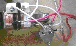 As you can see, the trick is to place the reed switch so that it runs along the length of the solenoid coil and so is located in the coil's magnetic field. This couples the coil's magnetic field to the reed switch as well as the magnetic field of the passing rotor magnet. This provides a magnetic feedback and turns the reed switch into an oscillator. So when the magnet passes the reed oscillates with the coil's field and causes very many pulses, typically 20 to 50 pulses per magnet pass. Amazingly, unlike the clamping diodes in the SSG, this is not wasteful. This reed switch oscillation actually reduces the input current. Instead of the reed remaining closed for the whole of the pulse duration, it switches on and off and so, less input power is drawn from the driving battery. I run the motor so that when the coil is energised, the magnet is attracted to the coil. Here is a trace across the charging battery: 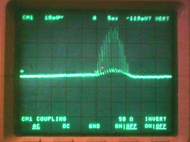 The trace above is from a motor that is only drawing 50 milliamps but is charging the battery many times faster than if it were drawing 300 milliamps with a single pulse per magnet pass! But there is more. Take a look at the following picture: 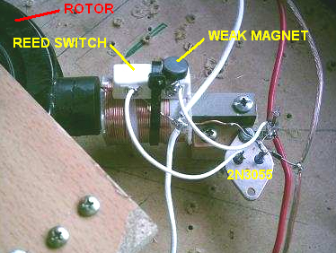 Using a very small and weak magnet, you can now control and adjust the reed switch. This allows you to adjust the switching so that the circuit oscillates continuously but still powers the passing rotor magnet. Below, is the trace across the charging battery and the battery is charging very rapidly although you are still paying for this as the input current will increase but nevertheless, you are really producing a vast amount of radiant energy for what is effectively, very little input current! Also, when you do this, the coils HISS very loudly! Yes, the coils HISS, not with a tone or frequency but with a hissing NOISE. 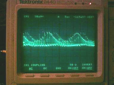 My prototype motor uses four of these circuit's, positioned 90 degrees apart around the rotor, and all connected in parallel. You can use just one reed switch to switch all four transistors and coils but it is more load and the reed switch does not hold up for very long. In fact, either way, if you use small reed switches, they will get worn and start to stick. I have bought larger reed switches but I am also working on an electronic switching version of this, although that is easier said than done. I have worked on this for a few months now so I have tried very many things and have not managed to match it with electronic switching yet. Limiting the current passing through the reed switch does not necessary increase the length of its operational life, besides which, doing that produces less radiant energy. Now having shown you all this, we are only half way to a complete radiant energy system which will provide continuous free energy. The above circuit and motor, even though they do provide large amounts of radiant energy, will still only give you a COP equal to, or close to 1 when regularly swapping over between the source battery and the charging battery. For battery swapping to work, you MUST have the second and equally important side to the system. The second side of the system is the radiant energy accumulator-converter. Before I describe the radiant-energy accumulator-converter, I want to highlight how important it is to build and experiment with the circuit described above. Only after adjusting and watching the input current and how the charging battery charges can you truly see how these radiant energy pulses are affecting the charging battery. In terms of why it works or how it provides so much radiant energy you have to understand that if the reed switch stays closed, which will happen when they get worn and start to stick, with the 9 millihenry crossover choke solenoid coil (bought off the shelf) which I use, the transistor is turned fully on and at virtually it's lowest resistance and so the current draw is about 6 to 8 AMPS for a single coil circuit!!! It seems this is a key requirement for generating these radiant energy pulses with a transistor. You have to switch the transistor fully on at maximum current for the coil and input voltage. This is another thing the SSG does not do well. But yet, in this circuit, when the reed switch is adjusted correctly, you can get the input down to just a few milliamps if you want! OK, now to the radiant accumulator-converter. The requirement for this appears to be because the charging battery is not very efficient at absorbing all of the radiant energy pulses. John Bedini had related this as being due to impedance matching but I am not sure of this at this stage, but impedance may be a factor. Because the charging battery does not absorb much of the radiant energy by itself, you MUST have an accumulator-converter to absorb and convert the radiant energy for the charging battery to use. Ok, that said, what is a radiant energy accumulator-converter? A Radiant Energy Accumulator-Converter (“REAC”) is nothing more than a dipole! But the larger the dipole the better! The dipole can be a battery but that is silly when we are already charging a battery. Well in that case, it is a special battery. It is a battery that is mostly composed of potential but little current. The higher the potential the better the accumulation/conversion but some current is still required to be able to pass the energy back and charge the charging battery. There are a number of traditional dipole's that fit what is needed. There is a simple long and raised wire antenna and ground, but this will not provide enough back current to charge our battery. There is an earth-battery setup, but unless you want to put in the effort and amount of materials to raise the voltage and still have some required current this needs a lot of work and materials. Finally, I found the best compromise to be "old, dead, sulphated lead acid batteries". At this stage of my research the condition of the battery does not really matter as long as it is “dead” and sulphated. As long as they are old and dead so that they can barely light up a 12V 100ma bulb, then they will do just fine. Gee I am glad I never threw away my old dead batteries that kept piling up. If you go down to a battery recycler or junk yard, you can buy pallet loads of old and dead Uninterruptible Power Supply (“UPS”) batteries for very little cost. When I say pallet load, I mean pallet load. The bigger the bank of these you get the batter. Connect them both in series and parallel so that if they where good, you would get anywhere from 48-120 volts. When connecting in parallel make sure that each 12 volt segment has an approximately even capacity in Amp-Hours. You can put this bank under your house or table or even bury them in the ground. It is no problem as you will never have to do anything to them again (as long as they are sealed). They will NOT keep running down. They are already run down. All you need them for is to use their potential as a dipole and their hidden capacity. The very small amount of current they will provide for the size of the bank due to the crystalline resistance of the sulphation is all that is needed to provide the free energy that the will convert the radiant energy pulses and feed it back into your good battery which is being charged. I believe that these sulphate crystals may indeed be the main component that is doing the radiant energy conversion for us. Now for how to connect up your ‘REAC’. See the following diagram:  You must connect the REAC directly to the charging battery as I have shown above. Amazingly, there is a great voltage different when you measure the voltage directly across the charging battery compared to the voltage measured across the REAC while the reed motor is running. This voltage difference is seen even with thick cables connecting them, but distance does affect it as well. You must have two separate sets of cables. One set going directly from the radiant energy charger to the charging battery and the other set from the charging battery to the REAC. I have run the above setup for over one month now. Below is a picture of the “dead” batteries which I use as an REAC. 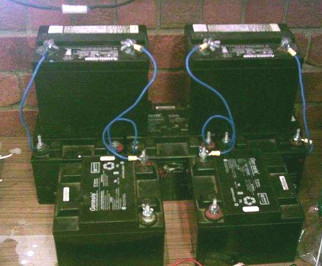 Using my good 33 Amp-Hour UPS batteries, I can charge them up from 10 volts to 14 volts in about 6 hours with the radiant energy reed motor running 4 coils drawing only 600ma. I can then swap the source battery with the charging battery and keep doing this until I have both batteries charged in about 24 hours. I have done this very many times and the charging rate appears to be improving over time. But one thing I want to make clear. If you think that I am somehow just using the stored energy in the REAC bank, if I do not use my reed motor, then the charging battery will not charge. If I try replacing the reed motor with a regular battery charger, the battery will take as long to charge as a normal battery charger would to charge it. When using the reed motor, the REAC is converting most of the radiant energy and providing the energy back to the charging battery. There you have it, a fully working radiant free energy system. Enjoy! -- Ossie Callanan The Self-charging Variation. One major disadvantage of most of these battery pulse-chargers is the fact that it is thought that it is not possible to self-power the device nor to boost the running battery during the battery charging process. There is one variation of the pulse-charger which does actually boost the driving motor as it runs, and one particular implementation of this is shown here:   The rotor weighs about five pounds (2 Kg) and is very heavy for its size, because it is constructed from flooring laminate, and has a thickness of 1.875 inches (48 mm) to match the width of the magnets. There are ten magnets size 1.875” x 0.875” x 0.25” (48 mm x 22 mm x 6 mm) which are assembled in pairs, to produce the most evenly matched magnetic sets possible. That is, the strongest is put together with the weakest, the second most strong with the second weakest, and so on to produce the five sets, each half an inch (12 mm) thick. These pairs are embedded in the rotor at equal 72O centres around the edge of the rotor. The battery pulsing produced by this circuit is the same as shown in John Bedini’s patent already mentioned. As the rotor turns, the trigger winding energises the 2N3055 transistor which then drives a strong pulse through the winding shown in red in the diagram above. The voltage spike which occurs when the drive current is suddenly cut off, is fed to the battery being charged. This happens five times during a single revolution of the rotor. The clever variation introduced here, is to position a pick-up coil opposite the driving/charging coil. As there are five magnets, the drive/charging coil is not in use when a magnet is passing the pick-up coil. The driving circuit is not actually active at this instant, so the micro switch is used to disconnect the circuit completely from the driving battery and connect the pick-up coil to the driving battery. This feeds a charging pulse to the driving battery via the bridge of 1N4007 high-voltage diodes. This is only done once per revolution, and the physical position of the micro switch is adjusted to get the timing exactly right. This arrangement produces a circuit which in addition to pulsing the battery bank under charge, but also returns current to the driving battery. Another variation on this theme is shown on YouTube where an experimenter who calls himself “Daftman” has this video explaining the circuit he uses in his Bedini-style battery-charging motor is here and his video of his motor running can be seen here and while his motor has been running for months in a self-powered mode. The Relay Coil Variation. One experimenter on the Energetic Forum has posted a video of his adaptation of the Bedini circuit at http://uk.youtube.com/watch?v=4P1zr58MVfI. He has found that adding a 6-volt relay coil into the feed to the base of the transistor has halved the power used and yet keeps the rotor at about the same rate of rotation. The circuit is shown here:  The build used has three electromagnet coils placed around a horizontal rotor: 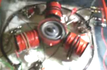 The Modified Computer Fan. Other more simple methods of getting this radiant energy charging of batteries are also available. One simple method is to skip most of the mechanical construction and use a slightly adapted synchronous fan. This method is shown by “Imhotep” in his instructional video which is located here. The original idea comes from John Bedini and the fan idea from Dr Peter Lindemann. The most common choice for the fan is a computer cooling fan - the larger the better. These fans usually have four windings connected like this:  To use these windings as both drive and pick-up coils, the fan is opened up by lifting the label covering the hub of the fan, removing the plastic clip holding the fan blades on the spindle and opening the casing to expose the coils. The wire post with two wires going to it then has one wire removed and a fourth post improvised by drilling a small hole and inserting a short length of wire from a resistor. The fourth wire end is then soldered to it to give this arrangement:  This produces two separate coil chains: 1 to 2 and 4 to 3. One can then be used as the drive coil and the other as the power pick-up coil which passes the very short high voltage pulses to the battery which is being charged. When opened up, the fan looks like this: 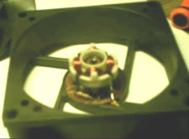 And the circuit arrangement is:  The fan is started by hand and then continues to spin, working as a fan as well as charging a battery. The current draw from the driving battery is very low and yet the radiant energy charging of the other battery (or battery bank) is not low. Please remember that batteries which are to be used with this radiant energy, need to be charged and discharged many times before they become adapted to working with this new energy. When that has been accomplished, the battery capacity is much greater than specified on the label of the battery and the recharging time also becomes much shorter. The circuit is adjusted with the variable resistor, which changes the transistor drive current, which in turn, alters the speed of the fan. It should be stressed that this device and the relay charger shown below, are simple demonstration devices with small coils and to get serious charging, you need to use a large-coil battery pulsing systems with a bank of lead-acid batteries being charged. This circuit is a clever implementation of John Bedini’s Simple Schoolgirl (“SSG”) design. As it can be a little confusing to know which of the four wires coming out of the modified fan to use, let me explain how they operate. You now have two pairs of series-connected coils inside the fan. An ohm-meter (or battery and bulb) will let you see which of the four wires are the two ends of each of those coils. The coils are symmetrical and so it does not matter which coil feeds the base of the transistor and which coil is driven by the collector of the transistor. It does not matter either, which way round the coil feeding the base of the transistor is connected but it does matter very much, which way round the drive coil is connected. Connecting it the wrong way round will not cause any harm but the fan will not operate because instead of the coil repelling the rotor magnets and pushing them on their way, it will attract them and oppose the rotation. So, if the fan does not spin when you give it a push, swap the drive leads over and it should work perfectly. The neon bulb protects the transistor but it also give a good indication of how well the battery being charged is being fed. Adjust the variable resistor to get the minimum current draw from the drive battery while still having the neon lit well and that should give a good performance. A very neat build of an 80 mm computer fan conversion to a pulse charger built by Brian Heath is shown here: 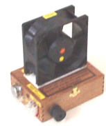 This unit runs with a PP3 9V battery as the drive battery, and charges a PP3 9V rechargeable battery when it is running. Both batteries are enclosed in the box in this very neat construction The Car Relay Charger. An even more simple charging method is also shown by “Imhotep” in another of his instructional videos at http://d1190995.domaincentral.com.au/page6.html. Here he adapts an ordinary 40 amp car relay, converting it from having a “normally open” contact, to operating with a “normally closed” contact. It is not necessary for you to do this as automotive relays with “normally closed” contacts are readily available and are not expensive. The relay is then wired up so that it powers itself through its own contacts. This causes a current to flow through the relay coil winding, operating the contact and opening it. This cuts off the current through the relay’s own coil, causing the contacts to close again and the process starts all over again. The repeated opening and closing of the relay contacts happens at the resonant frequency of the relay and this produces a buzzing noise. Actually, buzzers were originally made this way and they were used in much the same way as a doorbell would be used today. The circuit used is shown here:  As you can see, this very simple circuit uses only two components: one relay and one diode. The key feature is the fact that when the relay contacts open and current stops flowing through the relay coil, a very high voltage spike is generated across the relay coil. In transistor circuits which drive a relay, you will see a diode wired across the relay coil in order to short-circuit this high voltage at switch-off and stop the transistor getting destroyed by the excessively high voltage. In this circuit, no protection is needed for the relay. Any number of batteries can be charged at the same time. An ordinary 40 amp automotive relay like this: 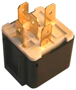 can have a “changeover” contact, which means that it has a “normally closed” contact and so can be used directly without any need to open or modify the relay itself. In this circuit, however, that reverse voltage is being used in a very productive way. These voltage spikes are very sharp, very short and have a very fast voltage rise. This is exactly what is needed to trigger an inflow of radiant energy from the local environment, into the battery. This battery charging current is not coming from the driving battery but is coming from the environment. The small current from the driving battery is just operating the relay as a buzzer. One user of this circuit commented that he was using a non-automotive relay with a greater number of turns in the coil, and he found that both of the batteries were getting charged at the same time, but of course, the drive battery was gaining charge at a slower rate. This will have been because the current draw with the more efficient relay was less that the rate of charging and so, even the drive battery gained power. Please remember that at this time, we have no instrument which can directly measure the flow of radiant energy into the charging battery. The only reliable way of assessing the inflow is to see how long it takes to discharge the charged battery through a known load. My experience with using relays for battery charging indicates that you get a better result if 24 volts is used to drive the circuit and as vehicle relays don’t have that much of a coil winding, there is a considerable improvement if a large coil is connected across the relay coil or coils as shown here:  When using one of these relay charging systems you will find that quite a lot of noise is generated. This can be reduced quite easily with a little padding and it does have the advantage of indicating that the charging system is running correctly. The "Alexkor" battery-charging system is very effective, cheap and easy to build. It is a version of the system described in Fig. 22B on page 7 of this web page:  While this description has been around for years, it is part of a discussion on the principles of the operation of EMF magnetic fields and pulsing in coils. 'Alexkor' has developed a practical circuit which he says works very well. It can be constructed as a single unit as shown here:  Here, the coil is wound with 200 turns of 0.7 mm enamelled copper wire and the actual construction is compact:  And to get an idea of the performance, Alex uses a capacitor to see the size of the voltage spikes produced by the circuit:  If building a circuit with a soldering iron and one of the commercial versions of prototyping board with copper strips is too difficult, then the circuit can be set up using a plug-in board like this:  The battery marked “1” provides power to run the circuit and the battery marked “2” gets charged. The resistors are all quarter watt. The enamelled copper 22 swg wire has a diameter of 0.711 mm and the coil can easily be wound on a cardboard tube. With a 30 mm (1.25 inch) diameter tube about 20 metres of wire would be needed and that weighs about 70 grams. I would like the output diode to be a UF5408 diode as the “UF” stands for “Ultra Fast”, but the wire leads are too thick to plug into a board like this and so the 1N5408 can be used, it is rated at 1000 volts and 3 amps. This is the first step in the process as the same circuit can be used to drive many coils of this type. The resistor feeding the base of the transistor is about 500 ohms for the prototype, but using a 390 ohm resistor in series with a variable resistor of say, 1K, would allow a good standard resistor value to be selected for each transistor/coil pair: This is the first step in the process as the same circuit can be used to drive many coils of this type. The resistor feeding the base of the transistor is about 500 ohms for the prototype, but using a 390 ohm resistor in series with a variable resistor of say, 1K, would allow a good standard resistor value to be selected for each transistor/coil pair:  As can be seen from the photographs, Alex uses preset resistors to adjust the settings to their optimum values. The simplicity of this circuit makes it very attractive as a construction project and using more than one coil should make for impressive performance figures. Alex says that the best results are achieved with just the one (1000V 10A) diode and not a diode bridge, which is borne out by the teaching comments on the above web site. Further development by Alex shows better performance when using the IRF510 FET instead of the BD243C transistor. He also has found it very effective charging four separate batteries and he has revived an old NiCad drill battery using this circuit:   It is possible to use various different transistors with these circuits. As some people have difficulty in working out a suitable physical construction for a circuit, here is a suggestion for a possible layout using an MJ11016 high-power high-gain transistor on stripboard.  Alexkor’s Self-Charging Circuit. This is a particularly simple circuit which allows a 12V, 8 amp-hour battery charge a 48V 12 amp-hour battery with radiant energy, in 20 hours using twelve times less current than a conventional charger would. The circuit can charge lithium, NiCad or lead-acid batteries The circuit used is:  The coil is wound on a hollow former, using two separate strands of wire of 0.5 mm diameter, giving a resistance of just 2 ohms. The strands of wire are placed side by side in a single layer like this:  A possible physical layout using a small standard electrical connector strip might be:  If the coil is wound on say, a 1.25-inch or 32 mm diameter plastic pipe, then the outside pipe diameter is 36 mm due to the wall thickness of the plastic pipe, and each turn takes about 118 mm, so around 24 metres of wire will be needed for the 200 turns. If 13 metres (14 yards) of wire is measured off the spool and the wire folded back on itself in a sharp U-turn, then the coil can be wound tightly and neatly with close side-by-side turns. A small hole drilled at the end of the pipe allows the folded wire to be secured with two turns through the hole, and the 200 turns will take up a length of about 100 mm (4-inches) and the two loose ends secured using another small hole drilled in the pipe. The starting ends are cut apart and the ends of each coil determined using a continuity test. An even more advanced circuit from Alex has even higher performance by using a high-speed transistor and a very fast-action diode, and a neon is not needed to protect the transistor:  The fast UF5408 diode used in this circuit is available, at the present time, on www.ebay.co.uk in packs of 20 for £3.84 inclusive of postage. The transistor drive to the battery bank can be replicated for additional drive and an additional ten transistors could be used like this:  The 2700 pF capacitor is recommended for each additional transistor, but it is not an essential item and the circuit will operate ok with just the one on the bi-filar coil drive section. A recent circuit design from Alexkor uses the tiniest of inputs; just 1.5 volts at a current which can be adjusted down from 4 milliamps to just 1 milliamp. This tiny circuit can charge a 12-volt battery, although admittedly, the charging rate is not very high as it takes ten hours per Amp-Hour to charge the battery. However, it is spectacular to get a input of just 1.5 milliwatts to charge a 12V battery. The circuit has very few components:  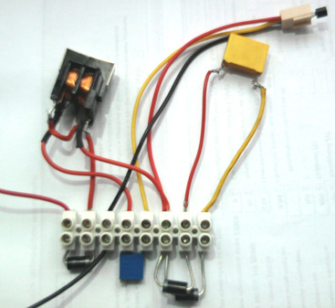 The coil is tiny, bi-filar wound on ferrite or with an air-core. In the circuit diagram, the dots on the coil windings indicate the start of the two side-by-side windings. This makes it clear that the start of one winding is connected to the end of the other winding as well as to the positive side of the 1.5V battery. The variable resistor could be omitted and various fixed resistors tried until the 1 milliamp current level is reached. It should be emphasised that there is just one earthing point and it is a real connect-to-the-ground type of connection. Simple arithmetic will show you that if there is a charging current flowing into the battery to charge it, then even with an imagined 100% efficiency of the battery, the battery charge is many times greater than the draw from the battery driving the circuit. The circuit runs at a frequency between 200 MHz and 300 MHz. Alex uses a commercial “choke” from Farnell as shown here:  Jes Ascanius of Denmark has replicated this circuit and he makes these comments: The 10K variable resistor and the additional 1K resistor need to be 250 mW types as larger wattages cause a greater current draw. Also, the quality of the earth connection is important as his very efficient earth produces 60-volt pulses from the circuit (70-volts at night) and just by touching the earth connection can boost those pulses right up to 92-volts and so further experimentation may produce some other interesting effects. Alexkor’s most advanced circuit to date is the one shown here:  This circuit uses the PLA inductor shown above. The initial reaction of somebody familiar with electronic circuits might well be “this is impossible as the battery being charged is ‘floating’ as it is not connected to either side of the driving battery”. While that is true, the circuit works very well indeed and a battery bank of ten 1.2V Ni-Mh batteries rated at 1100 mAHr capacity which had been charged and discharged ten times before, is now charged by this circuit in just half an hour. The input voltage can be anything from 12V to 36V without the need to change any of the circuit components. The choice of transistor is important and the STW12NK90Z is a very high-performance, high-voltage transistor (available at the present time from www.mouser.com ), and while it is not cheap, I would strongly recommend its use if you decide to replicate this circuit. The SF28 diodes are also special components, rated at 600 volts and 2 amps, these are high-speed diodes, not to be replaced with any diode which happens to be available. The coil is most unusual in that it is just four turns of very thick copper wire, 3 mm to 4 mm in diameter, although aluminium wire can also be used. This power cable is wound on to a spool of 100 mm to 130 mm (4-inch to 5-inch) diameter. The tiny 5 nF capacitor needs to be rated at a very high 2000 volts. The real Earth connection at point “A” gives a 20% to 30% improvement in performance but if the circuit has to be portable, then it will work with the lower level of performance if the earth connection is omitted and point ”A” is connected to the 0V line of the input battery. While the above coils are air-core to allow high frequency operation, coils are generally much more efficient with some form of magnetic core, such as iron-dust or ferrite. While it is not likely to be able to operate at frequencies as high as 35 KHz, a very good material for coil cores is the metal of masonry anchors or "sleeve anchors":  This metal is immune to rusting, easy to work and loses all magnetism as soon as the magnetic field is removed. You can confirm this for yourself by placing a permanent magnet on one end of the bolt or the tube and using the other end to pick up a steel screw. As soon as the permanent magnet is removed, the screw falls off as the metal does not retain any of the magnetism from the permanent magnet. These anchors are cheap and readily available from builder's supplies outlets, including those on the internet. It is unlikely that this material could operate at more than 1,000 Hz and the circuit above gains a lot of it's performance from the high speed, fast switching and very short "On" time duty cycle. If you use the bolt section of one of these anchors, the conical bump at the end of the shaft will have a delaying effect on the build-up and release of the magnetic field and so it might be advisable to either file it down gently by hand, or to cut off the conical section. There will always be eddy current losses in any solid metal core, but that does not stop them being very effective in operation. As with everything else, testing an actual device is the key to good performance and sound knowledge. Sucahyo’s Charging Circuit In 2014, Sucahyo stated that some people found that pulse-charging batteries for a few times, caused those batteries to have “surface” charge where the voltage rose to normal without there being any corresponding genuine charge behind that voltage rise. This is not an effect which I have encountered, but perhaps I didn’t charge a battery enough times to reach the problem. Anyhow, Sucahyo has published a circuit which he has used on batteries repeatedly for four years without encountering a surface-charge effect. Pulse charging uses “cold” electricity and “cold” electricity can be converted to “hot” electricity by feeding it into a capacitor. Here is Sucahyo’s circuit:  Notice that the 1N4007 diodes protecting the TIP41C transistors are connected to the transistor base and not it’s emitter as is more common. The coils being used are just simple single-filar CCW-wound coils with a DC resistance of about 1 ohm. Each coil is wound around a ferrite toroid:  You will notice in the circuit, that the TIP42C transistors which are PNP type, are connected in a way which would be considered to be “wrong”. This method of connection is perfectly deliberate and it works well, drawing only a quarter of the current which would be drawn if they were connected the “right” way round and yet maintaining the same level of output charging current. As with any charger, it is not a good idea to overcharge the battery. The circuit (which Sucahyo calls “Stingo”) can charge a 1000 milliamp-hour AA battery in 15 minutes, a 12V 7 Amp-Hour battery in 5 hours and a 12V 70 Amp-Hour battery in 15 hours. There is additional information and discussion at this forum. Howerd Halay’s Battery Charging Techniques Howerd Halay of the UK stresses the major difference between “conditioned” batteries and all batteries which have not been conditioned. He says: to condition a battery or capacitor, it needs to be repeatedly charged with ‘cold’ electricity and discharged again. Cold electricity is either high frequency AC electricity or alternatively DC at high voltage. With cold electricity, the electricity flows outside the wires (Steinmetz) and so, Current does not equal Voltage divided by Resistance as Ohm’s Law suggests. Instead, Current equals Voltage x Resistance x a Constant “C” which has to be determined by experimentation. It is also possible to get cold electricity from pulsed DC, provided that the DC voltage is over 80 volts. If using that technique, then the sharper and faster the pulses, the better. When you first pulse an AC or DC capacitor, it behaves normally. After approximately 12 hours of continuous pulsing a change occurs in the behaviour of the capacitor. In the case of the water capacitor, it develops a nano coating on one side only. When measured with a resistance meter it shows no resistance at all. One can say that one side becomes quasi superconducting. In the case of an ordinary capacitor, there is no reason to believe that it behaves differently. The capacitor also charges much faster than before and when the power source is switched off it continues charging! Yes you read that correctly. In my case it fires pulses for up to 3 minutes after the power is switched off, which is why they are dangerous. The firing decays exponentially although I haven't yet tabulated it scientifically – I’ll leave that to other people to do. The result of this is that you can have two identical capacitors side by side. One behaves as if it is plugged into a charger, while the other capacitor behaves normally. All capacitors self-charge to a certain extent but “conditioned” capacitors are in a league of their own! I have tested a neon on a conditioned capacitor through two earth rods 10 feet apart. I gave up looking at the lit neon after half an hour!  I use a very low-powered high-voltage source with a power output of only 1.2 watts as I like to play safe with these things. With a low power source, I have charged batteries using pulses of up to 800 volts without the batteries showing any ill effects. Also, using one-wire electricity is safer as that transmits mostly voltage and so minimum current is fed. So, to condition a battery or a capacitor using cold electricity, you can use a circuit like this:  Here, the size of the voltage pulses fed to the battery or capacitor to be conditioned, is controlled by the strike voltage of the neon. The ordinary NE2 type neon lamps strike around 90V and so the 2N6509G SCR will feed pulses of about that voltage to the battery or capacitor. If two neons are connected in series and used instead of the single neon shown above, then the voltage pulses will be around 180V. This type of circuit appears to work better if several capacitors are used in series as shown here, as they seem to charge up faster and discharge faster as well. You have to leave the device running for a day to get the full benefit. I regularly charge a 1.6 Kw car battery bank, and after switching off, the battery bank voltage goes up!! I have also tried 5 seconds of ON time and two minutes of OFF time, and the capacitors continue firing pulses. However the rate of firing is much less when the power is off than when the power is on. If you fail to use the capacitors for a while - in my case it was three weeks or so - you have to start the conditioning process all over again. In my case conditioning them again was harder and seemed to take days rather than hours. The capacitors are COLD. The wires leading up to them and out of them are COLD, but if you get a shock from them, then that shock is HOT !! Because this charging process uses cold electricity, non-rechargeable batteries can be charged this way. In my case two out of three batteries recover their charge OK, and curiously they charge to a much higher voltage than their rated value. The battery can be replaced with a capacitor. Obviously, any battery or capacitor which is to be conditioned, needs to have be able to be charged with a voltage of not more than 70 volts per neon, so for example, a 96V battery bank would need two neons in series across the SCR of the charging circuit. This circuit will keep on charging the battery for up to three minutes after the input power is switched off. An even more powerful version of the circuit boosts the cold electricity power by using a choke. The neons will light much more strongly. The neons should pulse or you've got a short-circuit. In other words, if the neon(s) is lit continuously, it is a bad sign.  You can use a variable resistor in series with the input power to vary the pulse rate. Negative radiant energy is delivered which produces cold electricity and conditions all capacitors in the output section of the circuit. Be very careful with this circuit as it can kill you. This circuit is only for experienced experimenters. Capacitors will take about a day to get conditioned. This circuit is good for bringing dead car batteries back to life. When a battery is conditioned and the charging circuit input power is switched off, the battery will continue charging ! Once they are conditioned, you can charge 4 car batteries in parallel using just a 6 watt 12 volt power supply, or a solar panel. However, this description must not under any circumstances be considered to be a recommendation that you should actually build this circuit as this presentation is for information purposes only. The question has been asked, “why use five capacitors in series when any one of them can easily handle the voltage being used?” That is a good question as the answer is not at all obvious. The answer is because of the way that capacitors charge up. The voltage across a capacitor which is being charged, increases in a very non-linear way and it is generally illustrated like this:  The red lines show the average rate of charge and the steeper the line, the faster the rate of charge. The greater the charging voltage relative to the size of the capacitor, the steeper the start of the line is. Howerd uses this fact to his advantage by using just the first ten percent of the curve. This is done by connecting several high-voltage capacitors in series as shown in his circuit diagram. The combined set of capacitors charge up very fast indeed and before they reach 10% of their capacity the neon fires and the capacitor charge is driven into the battery (or capacitor) which is being conditioned. The intensity of that current is determined by the size of the capacitors in the chain, the larger the capacitors the more intense the pulse into the battery and as you can see, Howerd has chosen 2.2 microfarad capacitors of the plastic film type:  The ‘UFOpolitics’ Motor In chapter 2, there is a section on how an experimenter alters the wiring inside DC motors. This alteration has a major effect, boosting the output power by a major amount as well as providing an additional generated electrical output. One person who followed his instructions and rewound a tiny 3-volt 3-pole motor, then tried running that motor on a discharged 6-volt battery. The motor ran, slowly at first and then picked up speed. That seemed impossible as the motor draws 300 milliamps when running and the battery was just not capable of providing that current. However, impossible or not, the motor ran and not only did it run but it started recharging the battery driving it. This suggests that this is a self-sustaining system which provides output power and yet never needs to have the battery recharged. The way that this happens is that what we think of as “electricity” is actually a more complex thing called “electromagnetism”. We think of electricity and magnetism as being two different things, while in fact, they are two different aspects of the single entity electromagnetism. The electric component always has an efficiency of less than 100% which the magnetic component always has an efficiency which is greater than 100% - something which we usually don’t notice as we tend to ignore the magnetic component. In the case of this tiny 3-volt motor, it draws it’s running ‘hot electricity’ current from the battery. That causes rotating magnetic fields inside the motor and these generate ‘cold electricity’ which flows back along the supply wires and charges the battery. The 3-Kilowatt Earth Battery This battery does not need charging as such. Earth batteries are well known. They are pairs of electrodes buried in the ground. Electricity can be drawn from them, but they are generally of little interest as the power levels are not great. However, in his patent of 1893, Michael Emme, a Frenchman living in America determined how to get very serious levels of power from an earth battery of his design. In this particular unit which he describes in his US 495,582 patent, he gets 56 amps at just under 54 volts, which is three kilowatts or 4 HP. At that early date, there was generally, not much need for electricity, but Michael states that by selecting the number and connection method of the individual components, any desired voltage and/or current supply can be had. This, of course, is a simple system which involves no electronics. Disclaimer: This document is for information purposes only and must not be considered to be a recommendation or an encouragement for you to actually construct an earth battery of this kind. If you choose to do so in spite of this warning, then all responsibility for the results is entirely yours. Please bear in mind that some forms of construction utilise strong acids and careless handling of strong acid can result in skin and other damage. Protective clothing should be used when handling acids and an alkali should be ready for immediate use if careless handling causes splashes. Summarising his patent, Michael says: My invention relates to chemical generators of electricity where a prepared body of earth is the support and excitation medium for the electrodes or elements. Any number of elements can be assembled in the same piece of ground and connected in a chain or series of chains in order to produce the desired voltage and/or amperage. I find that several straight chains of elements can function separately provided that the gap between the chains is much greater than the gap between the elements which form the chain. Being quite separate, those chains can be connected in series to increase the voltage, or in parallel to increase the available current. It is necessary to prepare the soil in the ground in the immediate area around the electrodes which form each element in the chain.  Fig.1 shows five elements connected in a chain. This view is from above with the rectangles indicating holes in the ground where each hole contains seven separate pairs of electrodes.  
Fig.2 and Fig.3 show how individual electrodes are inserted into the prepared soil “C” which is surrounded by untreated ground “B”. Electrode “D” is made of iron and “E” is made of carbon.  Fig.4 shows how wedge-shaped electrodes can be used as an alternative construction. The advantage is that it is easier to pull a tapering electrode out of the ground.  Fig.5 shows the internal current flow circuits which operate when a chain of elements is used. The arrows indicate the direction of current flow.  Fig.6 shows a convenient method for periodically moistening the prepared soil areas. Soil of any type can be adapted for use with an electrical generator of this kind by saturating the soil immediately surrounding each pair of electrodes with a suitable solution which is rich in oxygen, chlorine, bromine, iodine or fluorine, or with a solution of a salt of an alkali. For the electrodes, I prefer to use soft iron for the positive electrode and hard pressed coke carbon for the negative electrode. The positive electrode is preferably a U-shaped bar of iron which has a circular cross-section. The two limbs of the U straddle the rod of carbon. Cast iron can be used but it gives a lower voltage, presumably due to the carbon and other impurities in it. Magnesium gives excellent results, producing 2.25 volts per electrode pair where carbon is the negative electrode.  
In implementing my invention, I level a piece of ground of sufficient area to contain the generating chain or chains. For instance, for three hundred positive elements each twenty inches (500 mm) long and two inches (50 mm) in diameter, bent as shown in Fig.3, the length of the piece of ground should be about 107 feet (32 metres) and 3 feet (1 metre) wide. I dig 43 holes at a distance of 30 inches (735 mm) apart (centre to centre) in a line. Each hole is 10 inches (250 mm) wide and 30 inches (750 mm) long and deep enough to contain the seven pairs of electrodes. The loose soil dug from the holes is mixed with the chosen salt or acid in order to make the generator active. For instance, if the ground is a vegetable mould, then commercial concentrated nitric acid should be added in sufficient quantity to saturate the soil, and manganese peroxide or pyrolusite should be mixed with the mass. If the soil has a sandy character, then hydrochloric acid or sodium carbonate (“washing soda”) or potash can be used. If the coil is a clay, then hydrochloric or sulphuric acid and sodium chloride may be used, the salt being dissolved in water and poured into the hole before the acid is mingled with the soil. The bottom of the hole is moistened with water and the prepared soil mixed with water to the consistency of a thick paste is then placed in the hole, surrounding the electrodes. The 43 groups of electrodes when wired in series as shown in Fig.1, will yield 53.85 volts and 56 amps, developing a total of 3015 watts. By increasing the number of cells, the capacity of the generator may be correspondingly increased to any desired power output. The prepared body of soil should be periodically moistened, preferably with the acid with which it was treated when first prepared for action. In a generator intended for continuous use, I prefer to provide a reservoir as shown as “A” in Fig.6, and run a pipe made of a material which is not attacked by the acid, along the chain of elements, with a nozzle over each element so that they all can be moistened very easily. Any accumulation of oxides or other products of the reaction between the prepared soil and the electrodes may be removed by raising the positive electrode and then forcing it back into place again. The carbon electrode can be cleansed by simply turning it without lifting it from its place. I find that the period of use of the generator during which no addition of salt or acid is needed, increases with the period of use. For example, during the first day of use, the acid or salt should be added after 10 hours of use, after which it will yield 26 hours of service, and then after another moistening it will operate for 48 hours, and so on, progressively increasing in duration between being moistened. This generator operates very consistently and reliably. Nowadays, we find mains voltage alternating current to be the most convenient to use. For a system like this, we would be inclined to use an ordinary inverter which runs on twelve volts or twenty-four volts. However, it needs to be remembered that the working input current is high and so, the wire used to carry that current needs to be thick. At 12V, each kilowatt is a current of at least 84 amps. At 24V that current is 42 amps (the inverter itself is more expensive as fewer are bought). Considerable household usage can be had from a 1500 watt inverter. The soft iron / carbon construction described by Michael Emme produces 54V from 43 sets of electrodes, indicating around 1.25V per set at high current draw. It seems reasonably likely that ten or eleven sets of electrodes would give around 12V at high current and three of those chains connected in parallel should be able to power a 1500 watt 12V inverter continuously at extremely low running cost. A Battery Charger for Just One Battery Johan Booysen of South Africa used electrolyser circuitry developed by Bob Boyce of America, to charge a battery. The important thing is that there was only one battery involved as the battery being charged actually powered the charging circuit. The battery involved was a 12-volt 18 Amp-Hour lead-acid battery which therefore has an efficiency of only 50%, which means that the battery has to receive twice as much current compared to the current which it can return afterwards. Johan used the battery to power a toy car which his young daughter played with. He charged that battery overnight so that she could use it the next day to drive around.  While the maximum speed of the car is only two or three miles per hour, the important point is that real, genuine energy is being put into the battery every night, energy which powers the toy car each day. A device of that kind, which can charge a battery without sunlight, without the need for wind and without the need for fuel, has major applications for people living in remote areas where there is no mains power and never will be as it is not economic to run power lines there. The question is: can such a device be made which is reliable and safe to use? DISCLAIMER: the following information is NOT for beginners but is solely intended for people who are experienced in electronics and who are aware of the dangers involved. Please understand clearly that I am NOT recommending that you should build anything based on the following information. First, please understand that you live in a dangerous place. You are surrounded and immersed in a sea of major energy which flows through you at all times. A lightning bolt is millions of volts with a current of ten thousand amps or more. That is a massive amount of power and I’m told that around the world, there are between 100 and 200 of those lightning strikes every second. The energy field would not even notice power flows like that even though to us they appear to be massive amounts of power. We do not notice the energy field because we have been inside it for all of our lives. It is said, and I’m inclined to believe it although I don’t know how to prove it, that it is not possible to create or destroy energy, and the most that we can do is convert it from one form into another (and when we do that, we generally manage to make the energy flow do useful work for us). One way to affect the energy field is to create a very short, very sharp, high voltage spike. That disturbs the surrounding energy field enough to make small ripples in it and we can sometimes gather those ripples and use some of them to do electrical work for us. Another known way to access this enormous energy field is to create a rotating magnetic field, but you need to be very, very, careful if you try doing that as you are messing around with an energy field of incredible power. You probably have heard of the famous equation E = mC2 and while most people think that it came from Albert Einstein, the reality is that it was produced years earlier by Oliver Heaviside and Einstein merely publicised it. What the equation says is that energy and matter are interchangeable and that a tiny speck of matter can be created from a very large amount of energy. Oliver Heaviside also calculated that the energy field which I have been trying to describe, fills every part of the universe, and that energy is so great that the amount inside one cubic centimetre is sufficient to create all of the visible matter which we can see in the whole of the universe. You don’t mess around with that energy field unless you know what you are doing, and even if you do know what you are doing, you still need to be very careful. Please understand that the electrical energy with which we are familiar, is a transverse wave while the universe is filled with longitudinal wave energy and those two forms are completely different, so the electrical effects which are familiar to you do not apply to the energy which charges Johan’s battery. Bob Boyce is an unusually clever and perceptive man. He experimented with rotating magnetic fields and was hit by lightning as a result. I cannot stress too much, that rotating magnetic fields are very dangerous indeed. Ideally, you want to avoid a rotating magnetic field. Bob developed a very effective and safe toroidal power supply for his high-performance HHO electrolyser. That power supply is an open system which provides more power to the load than is drawn from the battery and it looks like this:  Which for a low-voltage system (not needing high voltage for 100 electrolyser cells in series) would presumably be:  Here, the steady-state DC voltage from the battery has added to it, the waveform generated by the electronics board pulsing the toroid. Regarding toroids, Bob says that he does not consider ferrite or laminated iron to be suitable toroids because it is just not safe to use them in circuitry of this kind unless at very low frequency which means low efficiency. In these systems, there has to be a trade off between control and power and an controlled runaway is highly dangerous. Remember here, that this system is tapping into the energy source which powers the whole universe continuously and what comes out of Bob’s toroid is mainly that same longitudinal wave energy. In passing, almost all, and quite possibly all free-energy devices including solar panels, water wheels, wave-power devices, biomass, etc. are powered by this literally universal energy field of longitudinal waves. Looking at this in more detail, Bob’s toroid is a 6.5 inch (165 millimetre) diameter iron powder toroid sold by MicroMetals in America, and it is wound initially with the secondary winding which goes all of the way around the toroid:  The wire used must be single strand solid copper wire, coated with silver and covered with teflon plastic insulation. Different toroids operate in different ways and so would need experimentation using different wire types and number of turns in the windings. This secondary winding has to be wound with perfect accuracy giving exactly even spaces between turns around the outer edge of the toroid and it is then taped over with ordinary electrical tape (do NOT use fibreglass winding tape and do not use multi-strand wire as either of those will prevent the circuit from working properly). Three primary windings are now wound on top of the tape which is covering the secondary winding (note that the primary winding wire starts over the top of the toroid and is wound from left to right):  Again, it is essential that the wire used is solid, single-core copper with silver coating and teflon covering. The completed toroid is bound with tape and screened by being placed inside an earthed metal box. The drive signals for the toroid are like this:  A similar system with a divide-by-two to produce each of the lower frequencies has been tried and it was found that it did not work as well as having three separate oscillators which are near the harmonic frequencies but not an exact harmonic, as that produces a complex series of repeated heterodyning of the signals and the resulting overall waveform is much richer than would be expected. So, if you attempt to replicate the waveform using an Arduino or other PIC microprocessor board, it might be advisable to set the lower frequencies at an odd number of clock ticks so that a complex waveform is produced. It is actually cheaper and more convenient to use discrete components: 555 timer chips with multi-turn preset resistors so that adjustment can be made without stopping a test run. The highest frequency is the key frequency and the two lower frequencies are helpful but of lesser importance. When tuning the circuit, the highest frequency is adjusted to give the best output. Then the gating for that frequency is adjusted to find the lowest input current which still gives that level of output. Then that same procedure is repeated for the second and then the lowest frequency modules. You will notice here that each primary winding on the toroid is fed with its own separate signal and there is no suggestion whatsoever that the three windings are driven sequentially to form one of those very dangerous rotating magnetic fields. Although the above diagram may look slightly advanced, it is actually, very simple in broad outline. The circuits might be like this:  I am not very happy with the above circuit. We are working from a single voltage supply of a nominal 12-volts and the circuit has a signal generation section which operates at low-current, and a high current drive section for the toroid coil. The resistor and capacitor marked “B” are to provide power decoupling for the low current section with the PCP116 opto isolator separating the two sections of the circuit. However, that is not a very good solution as the current pulses along the power supply wire will definitely create high speed voltage fluctuations in that wire. There are a number of solutions. One might be to add in a small choke at point “A”, and/or provide a second supply wire connecting at point “A”:  All choke windings should be kept well away from the toroid windings to avoid inductive coupling, and they should be outside the screening box containing the toroid. No matter what arrangement is found to be suitable, three of these circuits are needed in order to drive the three separate windings on the toroid. The only difference in the second and third circuits is the frequency capacitor:    Please remember that it is Bob Boyce’s technology which is tapping into this extra power of the ambient background energy which surrounds and flows through us. Also, understand that what comes out of the toroid is not just conventional ‘transverse wave’ energy, but instead, it is mainly longitudinal wave energy which we cannot measure directly. Bob points out that if your load is capable of absorbing longitudinal currents, such as water or to a somewhat lesser degree, a light bulb, then this longitudinal wave power will run it. If the input energy is correctly configured, then that causes modulated longitudinal wave energy to flow out of the toroidal transformer wires because that input energy modulates the local longitudinal wave energy field. When the toroid is wound and driven for peak efficiency, the unit behaves as a Tesla magnifying transmitter and a Tesla radiant energy receiver, all in a single package. There is an energy gain in the process, which is why Tesla called it a ‘magnifying’ transmitter. This energy gain is produced by the small energy source which we provide, modulating the very much larger energy source which is the longitudinal wave dominant energy source of the entire universe, and then we capture and use this modulated energy to do useful work. The output of the toroid is a combination of conventional transverse wave energy and non-conventional longitudinal wave energy. It is the characteristics of the load which determines how much energy will be harvested from the longitudinal wave energy component of the output. Water only absorbs longitudinal wave energy if that energy is modulated at the correct frequency. Light bulbs and some motors can run directly on (“cold electricity”) longitudinal wave current, but they do so at reduced efficiency. Many modern appliances and items of electronic equipment would need to have the longitudinal wave energy converted to transverse wave energy in order to be able to operate on this energy. For the HHO gas production, the electronics and the toroid itself have been designed to produce dissociation of water in a relatively safe manner and that is why Bob insists that HHO experimenters stick with a pulsed field mode of operation. It is much lower in gain than a rotational field system would be and because of that lower gain it is much less inclined to go into a runaway condition where the output energy increases the longitudinal energy gain to the point where the system overloads and goes into avalanche runaway. By using water as the load, any increase in output energy is absorbed by the water and so it is a self-stabilising process. Even if an avalanche occurs in an HHO gas system, the low power density of the pulsed mode allows the water to absorb the power surge and that just causes more water to convert into gas. This means that in order to be safe, input energy must exercise full control over the tendency to self-feedback and a load MUST always be present when the device is running. Water is preferred because it does not burn out, it just dissociates. We tune the primary frequency to be one which works well with water. It is a frequency which allows the water to absorb the longitudinal component best. That is why using just pulsing DC does not give the same effect. DC does not contain the longitudinal wave energy to which the water is responding in a resonance drive system. Unfortunately, the best frequency for longitudinal energy absorption by water is affected by many factors, so we must strive to keep the system in tune for the best absorption of that energy. The other two frequencies enhance this energy collection process without greatly increasing the associated risks. Bob knows that this entire power technology sounds hocus pocus to those educated in traditional transverse wave energy behaviour, but longitudinal wave energy is very real and can be used to our advantage. Many inventions and devices have been built that can tap into this unseen and unmeasured energy. The average water for fuel experimenter has no clue as to how dangerous this energy side of the technology can be, hence the amount of work which Bob expended in trying to make a relatively safe pulsed version which the average experimenter can use safely. Otherwise, experimenters are likely to kill themselves when trying to apply a very dangerous technology to a very simple application, all in the effort to generate more HHO gas on demand. Bob is not the only one to do this. Meyer, Puharich, and others, have managed to tap into this energy is a safe and controllable fashion. When Johan tries to charge a lead-acid battery, there is no electrolyser filled with water to absorb an avalanche runaway. The only available water is in the acid contents of the battery and it is that which will dissociate into HHO gas inside the battery. That HHO gas mix is in the exact proportions for explosion back into water again. What has not been stressed is that the HHO gas produced is highly charged electrically and will detonate if the gas pressure exceeds about fifteen pounds per square inch. While any mention of an explosion is scary, the reality does not match up to what most people imagine. Earlier in this chapter, Ronald Knight who is an experienced battery tester (using only transverse wave energy), explains the situation clearly: I have not heard of anyone having a catastrophic failure of a battery case in all the energy groups to which I belong and most of them use batteries in the various systems which I study. However, that does not mean that it cannot happen. The most common reason for catastrophic failure in the case of a lead-acid battery, is arcing causing failure in the grids which are assembled together inside the battery to make up the cells of the battery. Any internal arcing will cause a rapid build up of pressure from expanding Hydrogen gas, resulting in a catastrophic failure of the battery case. During the manufacturer’s testing, the battery is charged with the maximum current which it can take. If the battery does not blow up due to internal arcing during the initial charge it is highly likely that it will not blow up under the regular use for which it was designed. However, all bets are off with used batteries that have gone beyond their expected life. I have witnessed several catastrophic failures of battery cases daily at work. I have been standing right beside batteries when they exploded and I have only been startled by it. I would suggest that when testing new, unorthodox circuitry such as this, that the battery is placed in a robust box which has vents covered with baffles so that gas can escape freely but any acid or fragments of case are kept inside the box. Personally, I have never had a battery explode, nor have I ever seen an exploded battery. I understand that Johan connects the circuit output back to the battery in this way:   The choke shown in red in the diagram is about 18 turns on a small toroid which seems okay, but the two other coils appear to be just six or seven loops in the connecting leads, not wound side by side on a magnetic former, but just left as if shortening the cable length 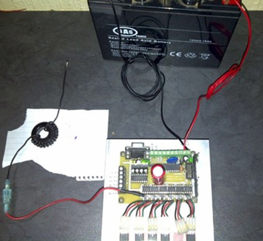 Consequently, it is distinctly possible that those two chokes have been omitted as the inductance of those loops must be very low indeed. The point of a choke is that it will pass DC while blocking sharp (transverse wave) voltage spikes. If those two chokes are as ineffective as they look, then the circuit would be:  While the photograph above appears to show a fuse placed in the output wire before the choke, I am doubtful about doing that. The speed of longitudinal energy is so great that a fuse is most unlikely to operate fast enough to be any use. Also, longitudinal (“cold”) energy has the reverse effect to what is expected with transverse wave (“ordinary”) energy. Any fuse has a resistance and is supposed to blow when it burns out through raised heat caused by excessive current flowing through it. Transverse energy would cool the fuse rather than heat it. However, a fuse might well have an enhancing effect on the whole charging process because while a resistance impedes the flow of transverse wave energy it actually boosts the energy flow of longitudinal energy, drawing in additional power from our surrounding energy field. In a runaway power surge, the fuse would not be helpful but when running normally, it might well be. Let me stress here that this is only my untested opinion and, unlike Bob Boyce, I am certainly not an expert in this technology. Let me stress again that this is NOT a recommendation for you to attempt to build or use something of this nature in spite of the fact that it has worked well for Johan. We need to remember that Johan was using a more advanced version of Bob’s electronic circuitry, one whose details have not been released. Because of that, it may be necessary to place a diode between the circuit output and the battery Plus terminal. This information is only a suggestion for experimentation which might just possibly be carried out by experienced electronics experts. A Fast-Charge Joule Thief Variation This somewhat unusual arrangement for a battery charger comes from Rene who has posted a video about it here saying that it charges batteries very quickly.  The technique is to use a mains power supply unit of twenty volts to operate the circuit in conventional mains charging mode but instead of connecting the mains supply to the minus of the battery being charged, a simple Joule Thief circuit is inserted in that line. This means that the Joule Thief circuit operates on the voltage difference between the mains supply and the charging battery’s present voltage. As the battery charges up, the Joule Thief working voltage drops. Rene says that the diode across the mains unit is needed but he doesn’t know why. While this is an interesting circuit, let me just express a few opinions, on it, and let me stress that these are only opinions as I have not built and used this circuit. Charging batteries from the back-EMF voltage swings produced by coils when their current is cut off, generally requires the negative of the battery being charged to be connected to the positive of the battery which is powering the circuit. This is not an essential feature of those circuits, but it is done because if you don’t, then current will flow directly from the powering battery into the charging battery. However, in this case, that is exactly what the designer wants to happen and so there is no obvious reason why there should not be a common negative line. That means that an ordinary 14V mains battery charging unit can be used and the Joule Thief can operate with a fixed voltage level. Unless Rene’s design gains charging power by having the Joule Thief circuit in series with the charged battery, I would suggest that the circuit might work better like this:  That arrangement gives the mains charging as before and constant voltage supply to the Joule Thief circuit which adds charging pulses to the mains DC supply to the battery being charged. Charging circuits from Charles Seiler In August 2009 Charles Seiler published some battery charging pulse circuits which are interesting. The first is based on Alexander Meissner’s 1913 circuit which looks like this:  This is a slightly unusual circuit which is compact and efficient. The 10K fixed resistor drops the voltage across the 10K variable resistor to about 6V to make the tuning easier. The variable resistor is adjusted so that the transistor is just about to switch on, and then the additional drive from the capacitor/coil pair makes the transistor switch on rapidly. Charles has altered this circuit by replacing the frequency control capacitor “C” with the internal capacitance of the battery being charged, making the charging rate proportional to the state of the battery being charged:  When set correctly, this circuit runs cool without any need for a heat sink on the transistor. The size of the capacitor is not critical and can be adjusted for the best performance. The coils are wound with equal lengths of wire and wound with the wires side by side, either air-core or with an insulated welding wire core like this:  Charles states that the low coil resistance is helpful for charging lead-acid batteries as they have a very low internal resistance of about ten ohms. The coils are wound with 200 to 400 turns but in spite of that, the current drawn by the circuit is small. The circuit can oscillate at 500 kHz but the rate of oscillation is affected by the state of the battery being charged and will typically be only 100 Hz to 2,000 Hz with a fully discharged battery. The pulse rate depends on the charge level of the battery as the battery is part of the timing mechanism of the circuit. One very important point is that the circuit has no protection against over-voltage and the 3055 transistor is only rated up to 60V, so if the circuit is switched on without the charging battery being connected, then the transistor will definitely be destroyed. Another circuit suggested is the one shown below. This is a very unusual circuit:  In this circuit, the four (or more) coils are wound as one unit with all four wires laid down side by side. The additional diodes are there to protect the transistors and the base resistors are adjusted to give a realistic current flow into the circuit which keeps the transistors cool when the circuit is running. Personally, I have always found pulse charging circuits to be temperamental and subject to a wide range of performance without any circuit change (that, of course, may be due to my poor constructional skills). However, if any charging circuit charges the battery faster than the current draw, then battery self-charging is possible. For that, a circuit like this can be used:  With an arrangement like that it is very encouraging to see the battery voltage rising and rising. The choke is only needed to block the charging voltage spikes from reaching the oscillator circuit. However, the oscillator circuit has to be COP>1 for this to work, but many of the circuits in this ebook have that characteristic. I have found the secondary winding of a 12V 300 mA mains transformer to be an effective choke. The Joule Thief as a simple Battery Charger The idea is to charge almost fully discharged batteries using only those almost fully discharged batteries to do the charging. This project uses one of the most simple and robust circuits ever produced and that is the “Joule Thief” circuit. This most impressive circuit was shared by its designer Z. Kaparnick in the "Ingenuity Unlimited" section of the November 1999 edition of the "Everyday Practical Electronics" magazine. The circuit is very, very simple, being just one transistor, one resistor and a coil. The circuit originally was used to light a Light Emitting Diode (“LED”), but it can be used for much more than that. This is the circuit:  The original coil was made of two strands of wire wound side-by-side around a small ferrite ring or “toroid”. The circuit automatically oscillates, generating a much higher voltage at the collector of the transistor, and while the battery voltage is not nearly enough to make the LED light up, the circuit lights it quite easily. It is not necessary to wind the coil on a ferrite ring as a paper cylinder is perfectly adequate. The circuit was then adapted by Bill Sherman and used to charge a second battery as well as lighting the Light-Emitting Diode like this:  I have used this type of circuit without the LED, to charge a rechargeable battery from 0.6 volts to 1.34 volts in just one hour, so it is certainly effective as a battery charger. The circuit is like this:  However, the circuit has a minor weakness in that if the drive battery has a voltage greater than the charging battery voltage plus the voltage drop across the diode, then the driving battery will feed current directly to the charging battery through the green winding shown above and on through the diode. That can be overcome by putting the batteries in series like John Bedini did. The current which flows into the battery being charged also flows into the drive battery:  The coil can be wound quite easily. A pencil makes a good former for a coil, so cut a strip of paper 100 millimetres wide and wrap it around the pencil to form a paper cylinder several layers thick and 100 millimetres wide and seal it with Selotape:   Make sure that when you pull the paper cylinder together with the Selotape, that you don’t stick the paper to the pencil as we will want to slide the completed cylinder off the pencil after we wind the coil on it. The coil can now be wound on the paper cylinder, and for this, it is convenient to use two fifty gram reels of enamelled copper wire. The wire which I used is 0.375 millimetres in diameter. There are many different ways to wind a coil. The method I use is to make three or four turns like this:  And then hold those turns in place with Selotape before winding the rest of the coil. Finally, the right hand end of the coil is secured with Selotape and then both ends are covered with electrical tape as Selotape deteriorates with time. While this coil has been wound with only one layer, if you want, an extra single covering of paper can be used to cover the first layer and a second layer wound on top of it before being taped and slid off the pencil. While the diagrams above show the strands of wire in two colours, the reality is that both wires will be the same colour and so you end up with a coil which has two identical looking wires coming out of each end. You make the wires at each end more than the length of the coil so that you have enough connecting wire to make the final connections. Use a multimeter (or battery and LED) to identify a wire at each end which connects all the way through the coil and then connect one end of that wire to the other wire at the other end. That makes the central tap of the coil “B”:  The coil needs to be checked carefully before use. Ideally, the joint is soldered and if the enamelled copper wire used is the “solderable” type (which is the most common type) then the soldering iron heat will burn the enamel away after a few seconds, making a good joint on what used to be enamelled wires. A resistance test needs to be carried out to check the quality of the coil. First, check the DC resistance between points “A” and “B”. The result should be about 2 ohms. Then check the resistance between points “B” and “C” and that should be an exactly matching resistance value. Finally, check the resistance between points “A” and “C” and that value must be twice the “A” to “B” resistance. If it isn’t, then the joint is not properly made and needs to be heated up with the soldering iron and possibly more solder used on it and the resistance measurements made again. The simple circuit as shown can charge four AA batteries in series when the circuit is driven by just one AA battery. I have used a 1N4148 diode which is a silicon diode with a voltage drop across it of 0.65 or 0.7 volts and it has worked well. However, a germanium diode with its much lower 0.25 to 0.3 voltage drop is generally recommended, perhaps a 1N34A diode. It is also suggested that using two or three diodes in parallel is helpful. A complimentary or alternative method of raising the efficiency of the circuit is to add an additional bi-filar winding to the coil, making Lawrence Tseung’s “FLEET” circuit as discussed in chapter 5:  With this arrangement, the second winding is also made with two wires side by side and then the end of the first wire is permanently connected to the start of the second wire, leaving just one wire exiting from each end of the new winding. Current drawn from this new winding does not affect the current draw from the drive battery which is running the Joule Thief circuit. If you have an oscilloscope, then the circuit can be tuned for optimum performance by placing a small capacitor across the resistor “R” and finding what value of capacitor produces the highest rate of pulsing with your particular components. The capacitor is not essential and I have never used one but values such as 2700 pF are sometimes shown. I have used this “FLEET” circuit to charge two 12-volt lead-acid batteries, using one to drive the circuit which charged the second battery. Then, swapping the batteries around and repeating the process a couple of times. After that, the batteries were left for an hour to allow the chemical processes to stop, and then the voltages were measured. The result was that both batteries gained significant, real, usable power during the process. As the only power applied to the circuit came from the batteries, that is a significant result. Also, as lead-acid batteries are only 50% efficient and lose half of the charging current which you feed into them, the circuit had to be producing an energy gain with more than twice the output power compared to the input power. However, keeping things simple and concentrating on the Joule Thief circuit, if we represent a slightly improved version of the circuit which uses three charging diodes connected in parallel, like this:  Then we can feed it from a useful load rather than a battery. For example, if we decide to produce lighting using the 12-volt 24-LED arrays:  Then we might choose to use a commercial DC-to-DC converter like this one:  Like this:  This circuit works really well. The current fed to the DC-to-DC step-up converter is controlled by the voltage at point “A” and the overall resistance of the Joule Thief circuit. As shown, it draws about 70 milliamps and lights one or two of the LED arrays brightly for six hours when powered by one set of four of the Digimax 2850 mAHr AA-size batteries. During that six hour period, all of the 70 milliamps of current is fed into the Joule Thief circuit and that allows it to charge a second set of batteries. Six hours is the length of time that I personally have lighting on at night. That means that in addition to the six hours of charging already achieved, there remains a further eighteen hours during which the circuit could be used to continue battery charging. While the circuit shows a switch short-circuiting the converter to extinguish the light, there is actually no need to use such a high current during the remainder of the day, and so a two-pole switch can be used to disconnect the light and drop the current level to 20 milliamps by short-circuiting one of the diodes which reduces the voltage across the Joule Thief like this:  The circuit as shown so far has two sets of four batteries. It would be nice to swap between them every few minutes. Batteries which are providing power to a load don’t charge nearly as well as unloaded batteries being charged. However, the mechanism which switches between the two sets of batteries needs to have extremely low current draw in order not to waste current. One possibility for that would be to use a latching relay like this:  This is the electronic version of a mechanical two-pole switch. A brief pulse of current between two pins locks the switch in one position and later, a pulse of current between two other pins locks it in the other position. The current drain on the circuit would be almost zero. While standard NE555 integrated circuits can operate with a supply voltage down to 4.5 volts (and in practice, most will operate well at much lower supply voltages), there are several much more expensive 555 ICs which are designed to work at much lower supply voltages. One of these is the TLC555 which has a supply voltage range from just 2 volts right up to 15 volts, which is a very impressive range. Another version is ILC555N with a voltage range of 2 to 18 volts. Combining one of those chips with a latching relay produces a very simple circuit as the 555 timer circuit is exceptionally simple:  The capacitor used has to be high quality with very low leakage in order to get this waveform which is On for exactly the same length of time as it is Off. This is important if we want the two battery packs to receive the same length of time powering the load as the time they receive being recharged. A weakness of the 555 chip timer from our point of view is that it has only one output while we need two outputs, one falling when the other rises. That can be arranged by adding a transistor and a couple of resistors like this:  With this circuit, when pin 3 of the 555 chip goes low, the capacitor connecting it to pin 2 of the relay pulls that pin 2 voltage low and causes the relay to change state as the relay pin 15 is connected to +5V, causing a current surge through the coil as the capacitor charges. A few moments later, when the capacitor has charged up, the current drops away to zero. Five minutes later pin 3 goes high again and that switches the transistor on causing its collector voltage to drop rapidly to near zero. That pulls pin 1 of the relay down low causing it to change state before the capacitor has a chance to charge up. This is fine if the capacitors shown in blue are poor quality and their charge bleeds away in a period of five minutes. Nowadays, even cheap capacitors are generally much too good quality to allow that to happen and so we need to connect a resistor across the capacitor to create that drop in charge. But that additional resistor is connected continuously and so it needs to be of a high enough value not to waste any significant current – perhaps 18K would be a reasonable choice. An 18K resistor with five volts across it draws only 0.278 of a milliamp of current. Joule Thief circuits do not need anything like as much as 70 milliamps of input current if they are to charge a battery pack well. Consequently, we can use two or three Joule Thief circuits, all powered by the current flowing through the lighting LEDs. If the circuit is to be used by somebody who does not understand how it works, then it would be worth adding a battery voltage sensing circuit which switches off the charging system when the batteries are fully charged as the system may be left unused for several days if the owner is away from home. The timer shown here needs to have a perfectly matched On / Off ratio and with an output which falls to zero at the start of both the On and the Off periods. The capacitor is any large capacitor as it just smooths the transition from one battery set to the other battery set.  Or :  The current fed to the DC-DC converter controls the level of lighting provided. The current level is set by the number of diodes in series below point “A” in the circuit diagram. Adding an extra diode increases the current draw substantially. The diodes used are the very cheap 1N4148 type although one 1N34 germanium diode could be used if more accurate voltage control is needed. The light output is improved in quality by adding one or more extra LED arrays wired in parallel as the current is shared equally between all of the LED arrays and each becomes less dazzling as the light output is from a greater lit area. An additional advantage is that each LED runs at a much lower temperature and that improves reliability and lifespan. Here is a physical layout for a three Joule Thief design, using a 125 x 35 mm piece of stripboard, that is a piece which has fourteen copper strips each strip having forty-nine holes. Why that odd size? Because a piece that size was available as an offcut when the prototype was being built. The prototype layout is like this:  The red dots in the suggested physical layout indicate places where the copper strip on the underside of the board are broken. There is a video of this basic information here. There are various circuits which I have shown which use the well-known “Joule Thief” circuit as part of the design. These devices have worked well for me. However, in 2014, Sucahyo stated that some people found that pulse-charging batteries for a few times, caused those batteries to then have “surface charge” where the battery voltage rose without there being a corresponding genuine charge inside the battery. That is something which I have never experienced myself but that might be because I didn’t discharge and recharge batteries a sufficient number of times for me to experience the effect. Sucahyo uses this circuit: which looks rather complicated with two of the transistors connected upside down and protection diodes connected between transistor collector and base. Sucahyo says that he has used this circuit for four years now without experiencing any surface charge effects. My preferred form of Joule thief uses a bi-filar coil of 0.335 mm diameter wire wound on a paper cylinder formed around a pencil and only 100 mm (4 inches) long, as that produces a very cheap and lightweight circuit. As I understand it, the Joule Thief produces a rapid stream of high voltage spikes of very short duration. Those spikes cause the local environment to feed static energy into both the circuit and the circuit’s load device (typically an LED or a battery). While I have never experienced surface charge from a Joule Thief circuit, I tested some old Digimax 2850 mAHr test batteries which had been sitting unused for more than a year. These did indeed show a surface charge effect when load tested. The first test used one battery to drive the circuit and charged three batteries in series using this circuit: But no matter how long the circuit operated, it would not charge the output battery above 4.0 volts which is 1.33 volts per battery. The load test results were terrible with the voltages at one hourly intervals being 3.93V, 3.89V, 3.84V, 3.82V and 3.79V after only five hours of powering the load. That is ridiculous performance as those batteries managed 22 hours of load powering with the solar panel design. Perhaps the batteries were damaged. So I overcharged them with a main operated charger, reaching 4.26 volts which is 1.42 volts per battery and the hourly load testing results were 4.21, 4.18, 4.16, 4.15, 4.13, 4.12, 4.10, 4.08, 4.07, 4.07, 4.06, 4.05, 4.03, 4.03, 4.02, 4.01, 4.00 (after 17 hours), 3.99, 3.99, 3.98, 3.97, 3.97, 3.96, 3.96, 3.95 after 25 hours and 3.90 after 33 hours. Clearly, there is nothing wrong with the batteries so the effect must be a factor of the charging. Feeding static electricity into a capacitor converts it into normal “hot” electricity, but we want a very simple circuit, so the next step was to add in a 100 volt 1 microfarad capacitor which looks like this:  making the circuit:  With the battery on charge removed, the voltage on the capacitor reaches 22 volts. Charging the same batteries with this circuit reached 4.14 volts and produced load results of 4.09, 4.05, 4.01, 3.98, 3.96, 3.93, 3.90, 3.88, 3.85, 3.83, 3.81 and 3.79 volts after 12 hours which is much better than the 5-hour total previously experienced. However, obviously, something better is needed. The next step is to use a diode bridge of 1N4148 diodes instead of the single diode, giving this circuit:  Without the charging battery connected, this circuit gives 28 volts on the capacitor and the battery charging is good, giving load testing results of 4.18, 4.16, 4.15, 4.13, 4.11, 4.10, 4.08, 4.08, 4.06, 4.05, 4.04, 4.03, 4.02, 4.00, 3.99, 3.98, 3.97, 3.96, 3.95, 3.95, 3.94, 3.94, 3.93, 3.93, and 3.93 volts after powering the load for 24 hours. This seems to be a very satisfactory result for such a minor alteration. If two 1.2V batteries are used to drive the circuit, without a battery on charge, then the voltage on the capacitor reaches 67 volts, but that is not necessary for charging a 12-volt battery. Although the change is slight, the circuit operation is changed considerably. The capacitor does not discharge instantly and so, for some of the time between the sharp Joule Thief pulses, the capacitor supplies extra charging current to the battery on charge. This does not mean that the battery being charged is charged much faster and you can expect that full charging will take several hours. I have not yet tested it, but I would expect that by using two or more of these circuits simultaneously, should increase the rate of charge;  There is no need to restrict the battery on charge to a nominal 3.6 volts in any of these circuits as a single 1.2 volt drive battery can easily charge a 4.8 volt battery or larger. The value of the capacitor has a considerable effect and I suggest a one microfarad capacitor is a good choice. It has been argued that the two additional diodes on each side of the battery being charged are not necessary, although I have shown them to isolate the two circuits from each other. Patrick Kelly www.free-energy-info.co.uk www.free-energy-devices.com www.free-energy-info.tuks.nl www.free-energy-info.com |