|
Note: If you are not at all familiar with basic electronics, you might find it easier to follow parts of this chapter if you read chapter 12 first.
It is generally not realised that excess energy can be obtained from pulsing a flywheel or other gravitational device.  This fact has recently been stressed by Lawrence Tseung who refers to the extra energy obtained in this way as being “Lead-out” energy. This gravitational feature has been part of university Engineering courses for decades, where it has been taught that the loading stress on a bridge caused by a load rolling across the bridge is far less than the stress caused if that same load were suddenly dropped on to the bridge. This impulse technology has been known for some time and it is demonstrated driving a canoe in the video at this location but Lawrence points out the potential for using it as a method for gaining excess energy for practical use. In October 2009, Lawrence and his band of helpers ran public demonstrations of an early prototype electrical pulsing system which produces excess output energy of COP = 3.4, that is, with 3.4 times more output energy than the user has to put into it to make it work: 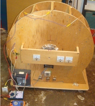 Video. Lawrence is busy developing this device further as he intends to construct one with a output energy excess of several kilowatts. Behind this device is Lawrence's "Lead-out" theory and for this he suggests a simple arrangement to demonstrate the principle. He presents the case of a rotor which has two substantial weights contained in two cylinders attached to the rotor: 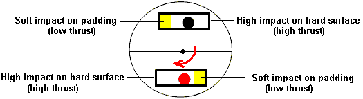 As the disc rotates, the ball falls down the length of the tube. At one end, the tube has a rigid cap which causes a significant impact when the ball hits it. The other end of the tube is padded and that cushions the impact which causes a net imbalance in the impacts and that maintains the rotation. There is a prototype implementation on YouTube but the implementation is not adequate and the disc stops rotating after five minutes. The YouTube video slot is located here and there are two significant problems with that particular build. Firstly, the tube rotation is too slow to be effective and instead of the weight falling under gravity and acelerating to a good speed before the impact, the weight just rolls gently down a minor slope and does not make a major impact. Secondly, the weights are far too small for the size of the wheel and there are only two weights providing impacts very widely spaced apart as the wheel rotates only slowly. One man made a ten-foot version and it rotated steadily for ten months after which time his wife insisted that it be taken apart as it was too noisy. I would suggest some modifications to the wheel as Lawrence is far too busy with developing his COP>1 pulse implementation. Firstly, the movement of each weight should be delayed until the tube is much nearer the vertical. This can be achieved by curving part of the tube like this: 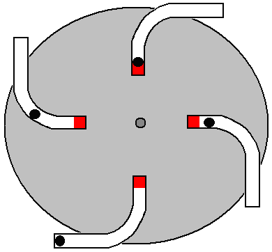 This way, the ball does not start rolling until the main part of the tube is near vertical. This allows a much greater acceleration and impact. The weighted ball should be much larger, say 2" (50 mm) in diameter and made of lead, in order to generate a significant thrust. Also, the cushioned ends of the tubes should be aligned with the pivot of the wheel so that any residual impact does not generate a turning force in the wrong direction. there is a negative turning effect due to the lever arm of the bottom weight. This turning force is only there for a small arc of rotation as the weight will roll inwards as soon as the tube section rises above the horizontal and as the tube then transitions into a circular curve, the movement inwards is gentle. It probably would be better if the tubes were angled slightly more in the clockwise direction, rather than exactly as shown in the diagram. Secondly, there should be eight tubes on the disc, four on each side and one side staggered by 45 degrees so that there is a driving impact every 45 degrees instead of the 180 degrees of the version shown in the YouTube video. With that arrangement of four times as many impacts, each substantially greater, and no significant reverse impacts, the wheel has a much better chance of successful rotation without needing to be particularly large. The wheel itself should not be light as it acts as a flywheel and a pulsed flywheel has already been shown to produce excess power. The wheel bearings should be ball races and not the closed variety because those ones are packed with grease and have a serious resistance to rotation. Instead, the open-sided variety of ball bearing should be used as they rotate very freely. Using straight tubes for illustration, each tube could be like this: 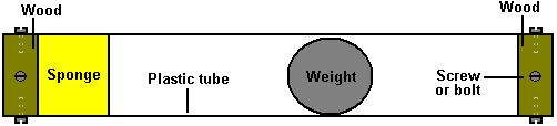 Here, a wood disc is fitted to each end of a piece of plastic tube and held securely in place with screws or bolts which pass through small holes drilled in the plastic pipe and screw into the wooden disc. A piece of thick sponge is glued to the disc at one end and the heavy weight inside the tube is not a tight fit so that it can move very freely inside the tube. Four of these tubes are fitted to each side of each disc used in the device as shown here: 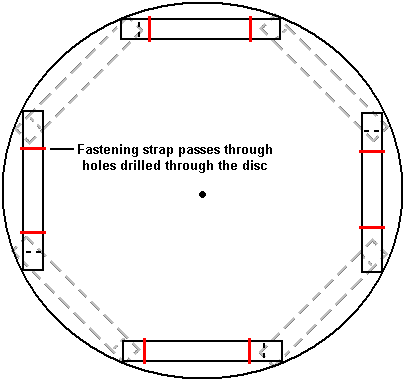 The four tubes attached to the back of the disc are 45 degrees away from the tubes mounted on the front of the disc. Each tube is attached securely in place with straps which pass through the disc and are secured on the far side. The tubes can also be glued in place to further strengthen the attachment. These eight tubes give an unbalanced impact for every 45 degrees of rotation. If two of these discs are attached to a common rotor shaft, then the second disc can be positioned 22.5 degrees around from the first one. That arrangement gives an unbalanced impact for every 22.5 degrees of rotation. If three discs were placed on a common rotor shaft and evenly positioned, then there would be an unbalanced impact every 15 degrees of rotation, which is 24 impacts per rotation. A two-disc arrangement might look like this:  If the rotor spins well, then it would be worth while attaching a series of magnets to the discs, being careful to keep each disc perfectly balanced. One or more air-core coils can then be used to determine if current can be drawn from the device without stopping the rotation. The coils should not have a magnetic core as that would cause a major drag on the rotation whether current was being drawn or not.  The Chas Campbell System. Recently, Mr. Chas Campbell of Australia demonstrated electrical power gain with a flywheel system which he developed: 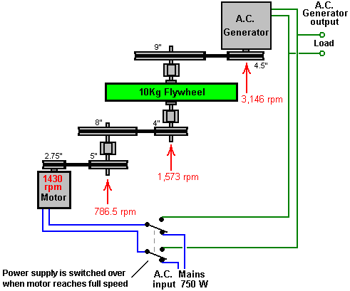 Let me explain the overall system. A mains motor of 750 watt capacity (1 horsepower) is used to drive a series of belts and pulleys which form a gear-train which produces over twice the rotational speed at the shaft of an electrical generator. The intriguing thing about this system is that greater electrical power can be drawn from the output generator than appears to be drawn from the input drive to the motor. How can that be? If the flywheel (which is red in the following photographs) is driven smoothly at constant speed, then there is a continuous inwards acceleration of every particle in the flywheel and that produces an energy gain, drawing in power from the immense energy field which surrounds us. That energy increases as the diameter of the flywheel increases. It also increases as the weight of the flywheel increases. It also increases if the flywheel weight is concentrated as far out towards the rim of the flywheel as is possible. However, Jacob Bitsadze points out that another mechanism comes into play. The effect is caused by the perpetual inward acceleration of the material of the flywheel due to the fact that it rotates in a fixed position. He also points out the importance of the gearing ratio of the shaft on which the flywheel is mounted. The important point is that Chas Campbell’s system is self-powered and can power other equipment. Now take a look at the construction which Chas has used: 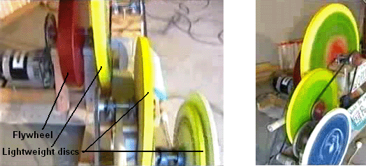 You notice that not only does he have a heavy flywheel of a fair size, but that there are three or four other large diameter discs mounted where they also rotate at the intermediate speeds of rotation. While these discs may well not have been placed there as flywheels, nevertheless, they do act as flywheels, and each one of them will be contributing to the free-energy gain of the system as a whole. A replication video with 750 watts input and 2340 watts output is here and this implementation does not appear to have a heavy flywheel as you can see from this picture, although the largest pulley wheel looks as if it contains considerable weight: 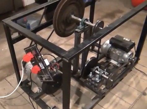 Jacob Byzehr. In 1998, Jacob lodged a patent application for a design of the type shown by Chas Campbell. Jacob has analysed the operation and he draws attention to a key design factor: 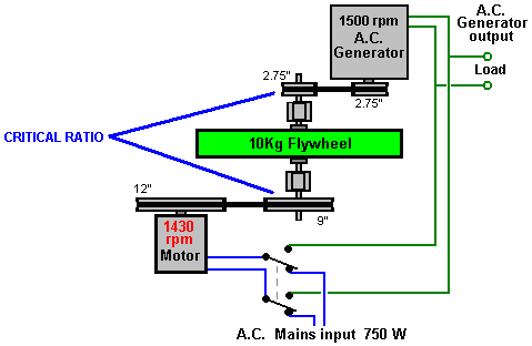 Jacob states that a very important feature for high performance with a system of this kind is the ratio of the diameters of the driving and take-off pulleys on the shaft which contains the flywheel, especially with systems where the flywheel rotates at high speed. The driving pulley needs to be three or four times larger than the power take-off pulley. Using Chas’ 1430 rpm motor and a commonly available 1500 rpm generator, the 12:9 step-up to the shaft of the flywheel gives a satisfactory generator speed while providing a 3.27 ratio between the 9-inch diameter driving pulley and the 2.75” diameter power take-off pulley. If a generator which has been designed for wind-generator use and which has it’s peak output power at just 600 rpm is used, then an even better pulley diameter ratio can be achieved. The Self-powered Generator of José Luis García del Castillo In 1998, Spanish patent ES 2,119,690 was granted to José Luis García del Castillo. I suspect that the auxiliary generators shown in the patent are only there to get the patent accepted by the patent examiner, rather than because they are actually needed. If that is correct, then the design is almost the same as Chas Campbell’s design, although built in a more compact form: 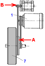 As Jacob Byzehr points out, an energy gain is achieved through inertial acceleration caused by having the pulley wheel “A” attached to the flywheel shaft, larger than the pulley wheel “B” attached to the shaft of the generator. As drawn, there is a major difference in those diameters. Here is an attempted translation of the patent: AUTONOMOUS ENERGY REGENERATION SYSTEM 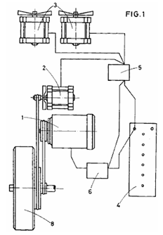 Abstract The system comprises an electric motor drive (1), a main generator (2), auxiliary generators (3), a battery (4), a charging regulator (5), and a speed regulator (6). The system is intended to generate its own operating power, and provide an extra supply for other purposes. The present invention refers to a self-contained system of energy regeneration, which in addition has several advantages set out below. Background of the invention It has been known for many years, how to construct machines which can generate electric current. These are known by the generic name of "electric power generators", consisting of rotating machine that transforms mechanical power into electrical power as a result of alternative action between a magnetic field and a moving conductor. However, the various types of generator which make up the current state of the art, require the help of a motor, which transforms mechanical power into electrical energy, and that motor requires an independent power source which must be supplied continuously. Thus, a system capable of generating its own power supply as well as providing an extra power supply for other purposes, is not known in the current state of the art. Summary of the invention The applicant for the present patent has designed an self-contained energy regeneration system, capable of producing its own operating energy in addition to generating a surplus which can be used in electrical networks using voltage converters required for any electrical installation, whether in homes, offices, warehouses etc.., with it is possible to reach places where it is difficult to install the power grid, allowing its use as an alternative source of energy other than solar or wind power. Other applications would be in the automotive field, as a power source for motorcycles, cars, etc. by connecting the system to the propelling motor, and thus achieving the necessary motion of the vehicle. Overall, the system is comprised of the following basic components:
The electric drive motor supplies the necessary electromotive force needed for the system to operate, the generator supplies power to the system, charging the battery and providing direct power to the traction motor when needed, or if the battery is fully charged, then just to power the motor. It can go provide direct mechanical power by using pulleys and belts, gears or any other means. The auxiliary generators are responsible for supplying backup power and can use propellers or be in the form of a turbine operating by the action of the wind or by gears attached to a flywheel placed in the traction motor. The function of the battery is to provide the power needed to start the motor and in addition, to supply any extra power that the engine may need during operation. The battery is recharged by the main generator which is driven directly by the motor. The function of the charge controller is to prevent the battery becoming overcharged. The function of the speed controller is to control the speed of the drive motor. The present invention offers the advantages described above, as well as others which will be understood from the example embodiment of the system described in detail below, to facilitate understanding of the features stated above, and introducing at the same time, various in addition to the present specification. It should be understood that the drawings are only by way of example and they do not limit the scope of the present invention in any respect, being just an example of one form of construction. Brief description of the drawings In the drawings: Fig.1, is a diagram of the system as one example of a practical embodiment of the invention. 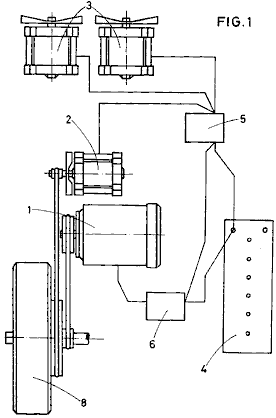 Fig.2 shows an alternative embodiment of this invention 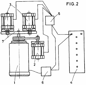 Description of a preferred embodiment of this invention As shown in the drawing, the self-contained system of energy regeneration, in accordance with an embodiment of the present patent, comprises an electric traction motor (1), a main generator (2), several auxiliary generators (3), a battery or accumulator (4), a charge controller and power supply (5), and a motor speed controller (6) 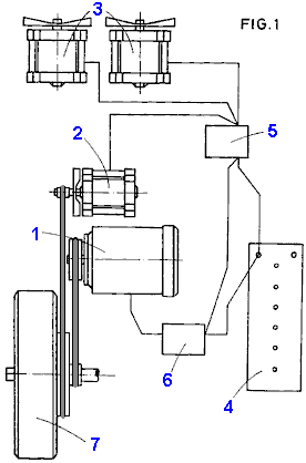 The electric drive motor (1) provides the necessary electromotive force for operating the system, and its voltage and power are selected in accordance with whatever size of system you wish to construct. The main generator (2) supplies power to the system, firstly, to recharge the battery (4), and secondly, direct power to the motor (1) if it requires it. When the battery (4) is fully charged, its charge is maintained by power from the motor, supplied by suitable pulleys or other method of transmission of mechanical power. The speed of revolution of the generator must be arranged through choice of the gearing between the motor and the generator, so that when the motor is operating at its maximum speed and drawing its maximum current, that the generator is spinning fast enough to supply that current. The main generator (2) will be therefore connected electrically to the battery (4) and mechanically to the motor (1). The auxiliary generators (3), are in the form of a turbine, operating by wind action or by gears attached to a flywheel (7), driven by motor (1), as shown in Fig.2. These auxiliary generators (3) provide reserve power for the system. The battery (4), must have a capacity which exceeds the maximum power of the motor (1), and its role in the system is to provide the power needed to start the motor (1), and to supply any extra energy which the motor (1), may need during operation. The battery is recharged directly by the main generator (2) which is driven by the motor (1). The charge controller and power distributor (5) is positioned between the main generator (2), the auxiliary generators (3) and the battery (4). Its job is to regulate the current draw from the battery (4), to prevent excessive current draw. It also distributes any surplus power as a direct feed to the generator (2) and the drive motor (1) when it needs additional current. The auxiliary generators (3) can either provide additional power to the motor (1), or their power output may be used for any other power needs. The speed regulator (6), is intended to regulate the speed of the motor (1), this adjustment is gradual, and is adjusted to match the intended use of the system. System applications can be many and diverse, noteworthy among which are uses in the automotive field, where it can be used as a means for propelling cars and other motor vehicles, with the motor (1) connected to a drive wheel which propels the vehicle. In these applications, the auxiliary generators (3), can be fitted with propellers or be turbine-shaped, so that the passing wind provides extra energy to the electrical system. With electric vehicles, only the main generator is connected to a drive wheel. Other applications for this system are in the field of energy supply, i.e. use in electrical networks. The advantage of using this patented system is that the power supply is practically inexhaustible and clean, and subject only to component wear and tear during operation. Its operation is as follows: Battery (4) provides the energy needed to start the motor (1), and allows for the possibility of increased electrical input being needed at certain times during operation of the system. The battery (4) is electrically connected to the motor (1) through the speed controller (6), which is fed from the main generator (2) by the load distribution controller (5). The generator (2), is driven directly by the drive motor (1), and the transmission of motion from one component to another is through gears, belts and pulleys, or any other conventional means. The auxiliary generators (3) are electrically connected to the charge controller (5), and the battery (4), and their movement by the wind generates their own energy, having turbine blades or propellers, or through being spun by the flywheel (7) which is connected directly to the motor (1). The energy produced by these auxiliary generators (3) may be used for charging other batteries for later use, or used directly to power other electrical equipment or electrical installation networks. Through voltage converters it is possible to convert the voltage produced by the system to a voltage which is suitable for use in other equipment. The Wilson Self-Powered DC Generator Mr. Wilson of Texas built a self-powered generator system using an old table and some car parts. His construction was shaky, but in spite of that, it powered itself and other equipment. The table which he used was five feet (1.5 m) in diameter and 2-inches (50 mm) thick which means that it will have weighed at least 130 pounds or 60 Kilograms which is a substantial amount, well in excess of that used by Chas Campbell with his AC self-powered system. In this DC construction the system was driven by a standard, unmodified, off-the-shelf DC motor powered by two car batteries wired in parallel to give a larger current capacity. These batteries were kept charged up by two ‘generators’ from pre-1964 American cars (the closest available today are permanent magnet alternators). These generators also powered additional equipment and Mr Wilson pointed out that three or more generators could be run by the system, giving a substantial level of excess electrical power. The machine has to be described as ‘shaky’ because he chose to convert the table top into a V-pulley belt drive flywheel by driving a series of nails into the edge of the wooden disc, with those nails angled to form a V shaped gap through which he ran a pulley belt. After three days of continuous running, those nails started to come out, causing him to power the system down. This unit was built around 1990, and if anyone decides to attempt a replication, then I suggest that the rim of the wooden disc is grooved to take the belt rather than relying on nails. The arrangement was like this: 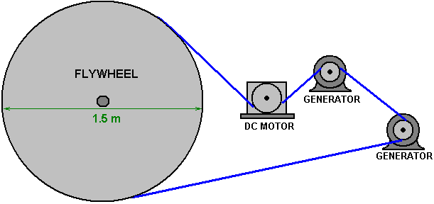 There was also a belt-tensioning roller which is not shown in the diagram above which assumes that the flywheel has been grooved to take the drive belt. Schematically, the arrangement was like this: 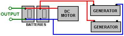 Here, the additional output can be used directly for powering 12-volt equipment or an inverter can be used to provide mains voltage and frequency. A typical inverter looks like this:  The battery power is connected to one end using thick cables to carry the heavy current, and one or more mains sockets are provided at the other end of the case, along with an On/Off switch and power indicators. Inverters come in many sizes and power ratings, generally ranging from 150 watts to 3,000 watts (3 kW). The more expensive ones are specified as “True Sine-Wave Output” but very few present day items of equipment will not run well on the cheaper versions which do not produce a true sine-wave output. Mr Wilson decided not to patent his design and instead wanted it to be open-source information for anybody to use freely. However, the Jesse McQueen patent shown in chapter 13 looks to be Mr Wilson’s design although the flywheel does not appear to be mentioned there. It should be stressed that the generator output needs to be high and so permanent magnet types are considered to be essential for this application. The specialised motor (and consequently, generator) winding methods of ‘UFOpolitics’ shown in chapter 2, raise efficiencies by a factor of typically 300% or more, and so would raise the output of this system very substantially if they were applied to the motor, or the generators, or both. John Bedini’s Battery Pulsing System. The Chas Campbell system is not an isolated case. On page 19 of the book “Free Energy Generation - Circuits and Schematics” John Bedini shows a diagram of a motor/generator which he has had running for three years continuously while keeping it’s own battery fully charged. At John’s web site John’s web site about half way down the page, there is a black and white picture of a very large construction version of this motor built by Jim Watson and which had an excess power output of twelve kilowatts. However, in spite of the flywheel in John’s design, it is not used directly to extract energy from gravity although it could readily do that. Instead, the design uses a very tricky method of trying to pulse the acid inside the battery with resonant pulses. That is a dangerous thing to do and if the pulsing is not exactly correct, it can make the battery explode. Strictly speaking, John’s dangerous design should not really be in this chapter on gravitational systems. John’s design has a motor which spins the flywheel and the flywheel shaft spins an aluminium disc with six permanent magnets embedded in it. The magnets have their South poles facing six helically wound coils of 200 turns each of 0.8 mm diameter wire. The coils are connected in series, so effectively it is a 1200 turn coil which is energised by six magnets simultaneously. John shows his switching mechanism as a mechanical attachment mounted on, but insulated from the motor shaft. The disc has just one conducting sector of about 100 degrees of arc. This would gives equal duration pulses except for the fact that his commutator brushes have adjustable positions allowing the pulse duration to be altered: 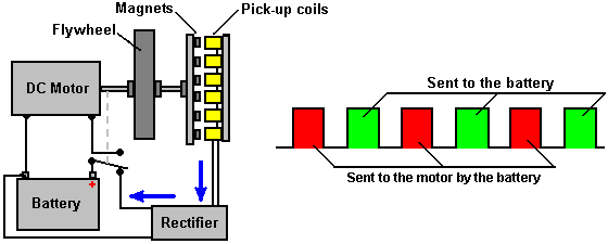 Let me stress again that the purpose of this system is not gravitational but instead is an attempt to shock the ions in the battery acid into self-charging through resonant pulses. In my opinion this is a highly dangerous idea and while it can be successful through nearly random adjustment of sliding contact positions, and a tuning capacitor across the generator, I certainly would not advise anyone to try doing that. John issues what he calls “stern warnings” against inexperienced people attempting to do this. It must be mentioned that perfectly safe motor-generators can be built – systems which have significant excess electrical output. The Water-jet Self-powered Generator. As described in more detail in Chapter 2 and Chapter 8, there is a very simple device based on a high-power water pump. In this system, a small quantity of water is pumped around continuously, in the same general style as an ornamental fountain. The difference here is that a high speed jet of water is produced and directed at a very simple turbine wheel as shown here:  Small discs are attached to the wheel at widely spaced intervals around it’s rim. The water jet hits these and applies an impulse to the wheel, driving it around, but also adding extra energy through those impulses. The waterwheel is coupled to a standard electrical generator via pulleys and V-belts. The system is started using the mains supply and then when it is running at full speed, the electrical supply for the pump is switched over from the mains to the output of it’s own generator. This is exactly the same as Chas Campbell does with his pulsed flywheel and both systems are capable of powering additional standard electrical equipment intended for mains use. Chas Campbell’s flywheel, John Bedini’s flywheel and this water-jet generator all demonstrate very clearly that environmental energy is readily available for us to use any time we choose to do so. All that is necessary is for us to construct one of these devices. The Centrifugal Energy Amplification Conversion Unit (“CEACU”) of Donnie Watts. Donnie Watts has designed a simple generator which is capable of providing enough electrical power to meet the needs of a typical household. The design is based on well known principles and this engine runs cold and is simple enough for many people to be able to build one. With a rotating cylinder of just 250 mm (10-inch) diameter, a self-powered output of ten horsepower can be achieved and ten horsepower is 7.5 kilowatts, so driving a generator with it would power a household. The output power increases with rotor diameter and with rate of spin and so in order to stop the device accelerating until it destroys itself, an inflow valve to limit the water entering the rotating cylinder is an important control requirement. What needs to be understood very clearly is that this is an exponential power engine. The output power is proportional to the square of the rotation speed, so double the revolution speed and you quadruple the output power. Also, the output power is proportional to the square of the rotor diameter, so double the diameter and that quadruples the output power. So, if you double the rotor cylinder diameter and you double the rotation speed, the output power goes up by a factor of sixteen. The basic Coefficient Of Performance for the design is four. That means that the output power is always at least four times greater than the input power. Initially, it is necessary to start the device with a 500-watt water pump, but when the rotation reaches 60 rpm the device no longer needs the water pump although it can be left running if desired. At 60 rpm, the pressure inside the rotor drum reaches the point where the suction caused by the water passing through the rotor jets creates sufficient suction to maintain the operation. But, remember that this is a positive feedback system, with an increase in speed causing an increase in power, an increase in water flow, an increase in speed of rotation, ….. and consequently, the engine will runaway self-powered and if you are not ready for that with a throttle on the rate of water flow into the cylinder, then the engine is perfectly liable to accelerate to the point where internal pressure destroys the engine. In broad outline, the design is like this: 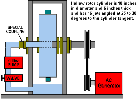 Most generators require to be spun at 3000 rpm or slightly faster. That speed can be achieved by the belt gearing between the output shaft and the generator’s input shaft. A generator of that general type could look like this 5 KW alterntor costing £325 in 2018: 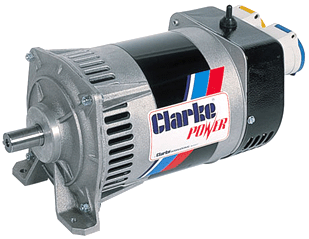 However, the output power of this design can be further increased by the inclusion of stainless steel thrust baffles on the inside of the housing. The idea is to have the jets of water strike a fixed surface at right angles to the jet and as close to the jet nozzle as possible: 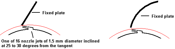 The curved plate version is theoretically more efficient but the difference is so slight that flat plates are generally used. Let me stress that this device is effectively a fuel-less engine with a substantial output and it can power moving vehicles or run an electrical generator. It can be built in various different configurations. 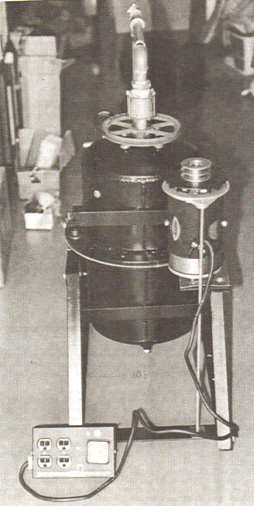 The 25th September 1989 patent application by Donnie C. Watts describes the operation of the device: CENTRIFUGAL ENERGY AMPLIFICATION AND CONVERSION UNIT Description of Unit The unit consists of two circular steel plates one eighth of an inch thick and four feet or larger in diameter, forming the exterior of a wheel. These plates are placed six inches apart on a hollow axle three inches in diameter. Between these two plates are four V-shaped pieces of sheet metal spaced precisely to form six-inch spokes which will direct water from holes in the central axle to the outer rim, while the inside of the V will form air pockets between the spokes. The ends of the V must not be closer than two inches to the outer rim of the wheel. All four V-shaped units must be precisely placed in balance with each other and securely welded to keep the air pockets and the water pockets separated. The outer rim of the wheel is made of a piece of one eighth inch thick sheet metal six inches wide, formed in a perfect circle and welded securely to the edge of the circular plates so that the area inside is completely enclosed. On this outer rim, directly in the centre, are placed between four and fifty water jets about the size of a football needle, slanted sharply to one side to give the wheel a turning motion. (The optimum number of water jets on the outer rim depends on the application, but the volume of water being expelled through the jets must not exceed sixty-six percent of the volume of water which can pass through the openings at the centre axle. The reasons for this are: 1. The water going out of the jets would be going out faster than the water entering the wheel which would result in no pressure near the outer rim, pressure which is essential for the running of the motor. 2. The water entering the wheel must go immediately into a puddle of water. The longer it remains a stream of water instead of a puddle of water, the more energy is wasted. Because the water being ejected through the exterior jets is always less then the amount of water available to the jets, a pressure build-up will occur near the outer rim. A spring-loaded pressure release jet (not shown) must be built into the exterior rim along with the other jets, but facing in the opposite direction to keep the wheel from over-spinning if the load (generator) is dropped or does not take enough power off to keep the wheel speed constant. There are several other ways to control the speed. The central axle is designed to have water going into one end of it, and an electrical generator attached to the other end of it. Between the water entry and the generator, very close to the wheel itself, would be very sturdy roller or ball bearings resting on, and attached securely to, a framework which will hold the wheel one foot off the floor. Water is forced into the axle via a high-volume low-power centrifugal force pump, approximately one half horsepower motor, at approximately 20 (US) gallons per minute depending on speed and power requirements. This motor and water pump is primarily to start the CEACU wheel and since the power from this is all added to the power output of the big wheel, I prefer to leave the pump running during operation. The entire unit (depending on application) can be put into a containment shell which can be pressurised or evacuated of air. If the unit is to be operated in an open field, the outer shell can be pressurised and the starting pump removed or turned off once the motor is running by itself. If the unit is to be operated in a garage or near a house, it would be operated at atmospheric pressure or in a vacuum, in which case it is necessary to leave the pump attached and running so that air bubbles do not form near the central axle. Also, the containment shell must be able to collect about ten inches of fluid in the bottom, waiting to be recycled through the wheel. Important Notes Regarding The CEACU: 1. The speed and horsepower curve of a self-energised motor is exactly the opposite of that of a normal motor. A normal motor reaches a power peak and then starts downwards. The CEACU power curve starts with a slow upward climb and then accelerates rapidly until the power line curve is almost vertical (just prior to disintegration if speed control is not being used). The CEACU motor will not generate more energy than is put into it before it reaches 60 to 100 rpm, depending on design and size. 2. As speed increases, air bubbles which occur in the working fluid will accumulate in the air pockets. The air pockets serve only to hold the pressure steady and give a gentle persuasive pressure that is multi-directional instead of just centrifugal, resulting in a steady pressure to the jets. It is not just possible or probable that the unit would blow itself apart by its own power (if the pressure were not released at some point or power taken off); it happens to be a fact. Air pressure will accumulate in the air pockets inside the wheel only after the wheel is going 60 rpm or faster. 3. The pressurised air in the outer rim of the wheel is essential because it pushes in all directions at once, while the water pushes in only one direction. In other words, centrifugally forced water is not interested in finding its way through the jets, it is only interested in pressing directly against the outer rim. The water holds the air in place at the same time that the air is forcing the water through the jets, and the water coming down from the axle keeps replacing the expelled water. This is why I keep saying over and over again, “Make it big enough, make it big enough”. Otherwise it would be no more workable than a small dam. 4. In order for this motor to work properly, the water coming down the spokes must not be restricted in any way until it reaches the outer rim. This is why we have six-inch spokes. The water resting against the outer rim cannot be moving about rapidly; we want the water sitting as still as possible under as much pressure as possible. 5. There are two primary factors which must not be altered in the design of this wheel, otherwise it will not work: A. The spokes must be very large and free of restrictions, because liquid in general tends to cling to anything it gets near. B. The speed of the wheel turning is essential to the centrifugal force required to build up the pressure near the outer rim, and for this reason the jets in the outer rim must be small in diameter and in large numbers so that the concentration is on speed instead of on volume (but not to exceed 66% of the water which can enter at the central axle). 6. Regarding the working fluid: Although it has been referred to here as “water”, the working fluid can be any kind of transmission fluid, oil, hydraulic fluid, etc., keeping in mind that the working fluid must also act as a lubricant for the bearings which are expected to last for ten to twenty years. I recommend regular off-the-shelf transmission fluid, which I have seen used alone in a car engine with lubrication results quite comparable to oil. 7. To the reader who would scoff at the energy which can be derived from pressurised systems, I offer the following facts: A. Six months ago, it was demonstrated on a TV programme that a highly pressurised stream of water about the size of a football needle (with no additives, but just pure water), would cut through a one-inch thick steel plate. That same stream was used to cut through a two-inch thick phone book, and it cut so fast that no matter how quickly the person holding the book moved it, the stream made a totally clean cut through it. B. Also, currently on the market is a turbine air motor made by Tech Development Inc. of Ohio and it has an output horsepower of 730, with an input air pressure of 321 psig, at 8400 rpm. This motor is only 7-inches in diameter and 14-inches long. This is not an over-unity motor, nor is it related to the CEACU motor in any way. I mention it only to illustrate what can be done with pressurised systems. So let’s accept the fact that we are talking plenty of potential, which will be found factual and workable in the CEACU motor. 8. The primary functional differences between, CEACU and damming up a river are: We create our own “gravity” and pre-determine the amount of that gravity by two methods instead of just one. The gravity in a dam can only be increased by building the dam larger; the CEACU motor can also increase the working gravity by increasing the rpm. This is done by adding more jets, right up to the point where 66% of the incoming water is being ejected. To use more of the available water than this would cause too much turbulence of the water inside the wheel. But keep in mind that there is always plenty of pressure inside the wheel to do the work it is designed for, providing that it is let run at a high enough speed to keep the pressure in the outer rim very high – in exactly the same sense that you don’t try to take off in your car until the engine is going at high enough rpm to handle the load application. 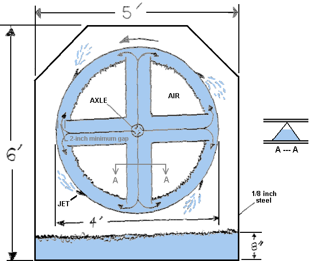 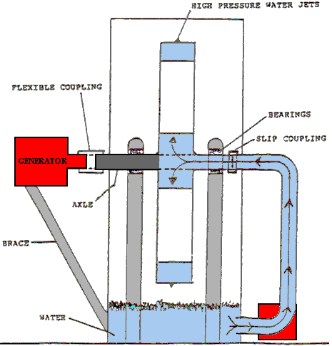 The two drawing above were produced by Donnie Watts and in them 4’ means four feet and 8” means eight inches. The only difficult part of this design appears to be the Slip Coupling where a stationary water pipe is joined to a rotating water pipe. While we are familiar with rotating lawn sprinklers which rotate using exactly the same principles as this Donnie Watts motor, namely impulse jet action, as shown here:  the key point is that the rate of rotation is low. That is entirely intentional as the manufacturer is considering the way that the various streams of water reach the ground. If you consider the rate of rotation, the fastest sprinkler is likely to be rotating at under 300 rpm which may be very much slower than our motor requirement. Researching the various couplings on the market, the rate of rotation quoted is typically 400 rpm or less, which may be why Donnie quotes such a large rotor drum size and 3-inch diameter supply pipe (axle). Suitable couplings could be coupling 1 or coupling 2 with a claimed 2000 rpm ability although purchasers state that they leak at speeds over 300 rpm: 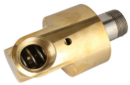 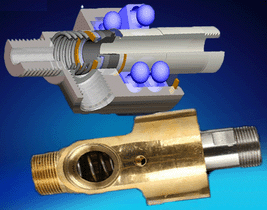 Video of interest: www.youtube.com Building the Donnie Watts Generator There are many different ways to construct a Donnie Watts generator. The method shown here is merely a convenient method of construction using 3 mm (1/8 inch) thick mild steel and a welder. The diameter of the rotating drum can be whatever you choose but the output power increases with the square of the diameter, so if you double the diameter the output power becomes four times greater. You start by cutting out two discs like this: 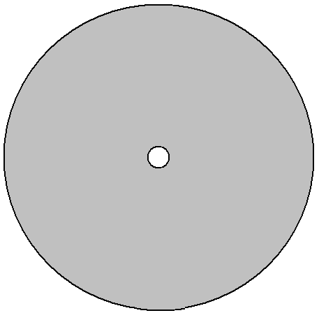 Then you weld on eight rectangles of steel 150 mm (6 inches) wide like this: 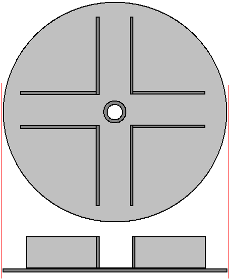 These strips are to channel the water (or other fluid) as it passes through the drum when the generator is operating. There must be at least two inches (50 mm) clear between these plates and the edge of the disc to allow easy flow of water past the plates. The 150 mm depth of the plates allows clearance for the second disc to be welded in place to form a drum. Seen from the side, it looks like this:  And then the outer rim of the drum is welded in place:  If you have never built anything in steel, let me assure you that it is not a difficult thing to do, and yes, I have built in steel, starting as a total beginner. However, while mild steel is easy to work and weld, stainless steel is much, much more difficult, so avoid stainless steel. Steel pieces are cut and shaped using an angle grinder like this:  And while the picture shows a handle sticking out of the side of the grinder so that you can use two hands, it is generally more convenient to remove the handle and just hold the grinder in just one hand as it is not heavy. When working steel, wear a pair of “rigger” gloves which are strong, reinforced gloves which will protect your hands from sharp steel edges and always wear eye protection. If you are going to be drilling steel, then a mains powered drill is needed as battery-powered drills are just not up to the job unless it is just a single hole. When drilling steel it is helpful to have an additional hand grip.  With the drill shown above, the hand grip clamps on to the ring just behind the chuck and can be set at any angle. Steel pieces are joined together by welding. Some welders are quite cheap. Most types can be hired for a day or half a day. It is also possible to shape the pieces and have a local steel fabrication workshop weld them together for you and making a good welded joint takes only a second or two. The really vital thing is never look at a weld being made unless you are wearing a welding visor or welding goggles, as you can damage your eyesight looking at a welding arc without protection. If you decide to buy a welder, then be sure to get one which will run on your house mains supply, otherwise you have to upgrade your house wiring to carry the higher current. This welder would be suitable, and at the start of 2016 it cost only £60 including tax which is about 82 euros or US $90.  With this “stick welder” the silver clamp on the right is attached to the metal to be welded and a 2.3 mm diameter coated welding rod placed in the black clamp on the left. The stick is then applied to the welding area and the coating on the welding rod becomes a gas cloud, shielding the hot metal from the oxygen in the air. When the weld has cooled down, there may be a layer of oxide on the outside of the joint and so the back of the wire brush is used as a hammer to break up the layer and the wire brush used to scrub the joint clean. However, the most important item of equipment for anyone doing welding work is a protective helmet. There are many different designs and widely varying costs. Many professional welders choose one of the cheapest types which look like this:  This type has a clear glass screen and a hinged safety filter to allow safe welding. Professionals adjust the hinge tension so that the filter can only just stay in its raised position. The welder then positions the joint pieces in their exactly correct position while looking through the plain glass, and when ready to start the weld he just nods his head which makes the filter drop into place and the weld is started. Never, ever, try welding without proper eye protection. Welding is easy to learn and it is a brilliant method of construction … but it has one major problem. When a joint is made the two pieces of steel melt and merge together. This can happen in a tenth of a second. Don’t put your finger on the joint to see if it is still hot, if it is, then you will get a painful burn and that should remind you not to do that again. That heat is the problem, because when steel gets hot it expands, and when it cools down it contracts. That means that if you were to set up a piece of steel at exactly a right angles and weld the pieces together then as the joint cools down it contracts and pulls the joint out of alignment:  Please don’t imagine that you can just push the vertical piece back into position as that isn’t going to happen because the joint is instantly very, very strong. Instead, you use two quick welds of equal size, with the second one being 180 degrees opposite the first one: 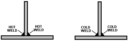 Then, as the welds cool down, they pull in opposing directions and while it produces stresses in the metal, the vertical piece stays vertical. Let the welds cool down in their own good time, taking perhaps ten minutes to cool properly. Do not apply water to the welds to speed up the cooling as that actually alters the structure of the steel and you really don’t want to do that. Metal can be cut quite readily using a cutting blade in your angle grinder but be sure to install the blade so that it rotates in the direction shown on the blade. The blade is likely to look something like this:  When cutting or grinding always wear protective goggles to make sure that you don’t get a metal fragment in your eye – eyes are not readily replaceable !! If you do get a small steel fragment in your eye, remember that steel is highly magnetic and so a magnet may help in getting the fragment out with the minimum of damage, however, it is much, much easier to wear goggles and not have the problem in the first place. The Donnie Watts drum spins on an axle and so needs a bearing on the axle pipe which supports it. The flow of liquid through the drum will be substantial and so Donnie recommends a 75 mm (3 inch) diameter pipe as the axle. That may sound excessive, but the reality is that it is quite difficult to force liquid through a pipe as there is much greater back-pressure than you would expect. So if you can manage a 75 mm pipe, then use one that big. The next step is to attach the outside strip to complete the basic drum. If you are great at bending 3 mm thick steel then do that but most constructors will find it much easier to weld, say, 32 strips 150 mm tall, around the outside of the drum (that actually makes it easier to attach the nozzles to complete the drum at a later stage. Here, we will assume that the drum is being built by a professional steel fabrication shop which can bend 3 mm thick steel to the required curvature, that is, to the diameter of the drum:  The outer edge of the drum is welded all along it’s length. The weld needs to be airtight but please understand that due to heat stress, long welds need to be done in short lengths of say, 25 mm in length or less and allowed to cool before the next weld is made. The technique is to make this series of short welds spread out along the length of the long weld and when those welds have cooled down, then they are each extended for another 25 mm. Slow and careful construction is easily the best method. We now need to attach nozzles through the outer wall of the drum. A hole needs to be drilled through the outer wall for each nozzle. As with all holes drilled through steel, the hole is drilled at right angles to the steel, that is perpendicular. I’m not saying that you can’t drill a hole at an angle, but it is very, very difficult to do without breaking the drill bit and it is very difficult to hold the drill steady enough to get the hole started. We want to have the jet of liquid leave the nozzle at 25 degrees to the face of the steel. We also want the jet orifice to be 1.5 mm in diameter. So we need to construct jets from steel pipe with that internal diameter, insert them through the outer wall of the drum and weld them in place: 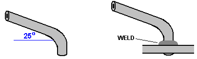 How many jets? I would suggest sixteen, but the number is not critical. The jets of water are more effective if they strike a nearby surface, so we attach a series of baffle plates to the outer housing. How many baffle plates? I would suggest sixteen or thirty two. The diagram drawn by Donnie shows angled top edges, but it is probably easier just to use square plates as there is less cutting and welding if you do. The housing plates need to be 300 mm wider than your drum and have 150 mm clear above it and 150 + 200 = 350 mm clear below it as the bottom of the housing acts as a sump for the liquid which passes through the jets: 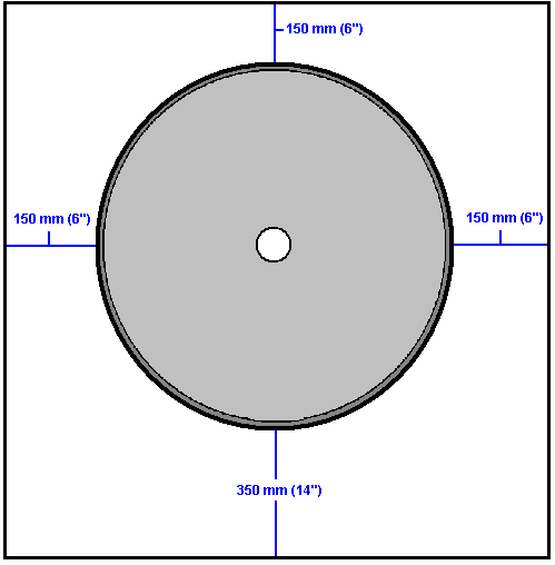 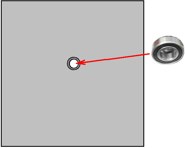 The baffles are welded to the back plate of the drum housing, but be sure that they clear all of the nozzles welded to the drum: 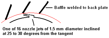 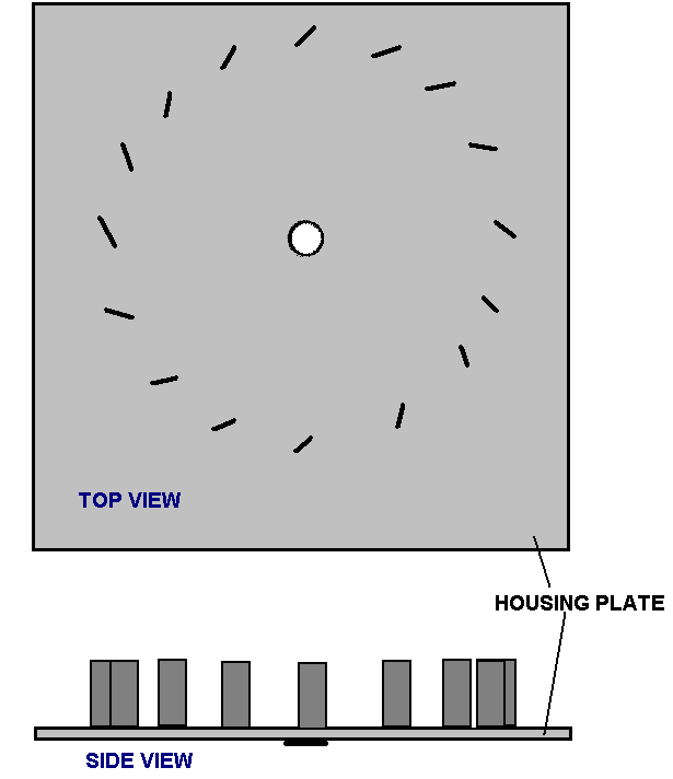 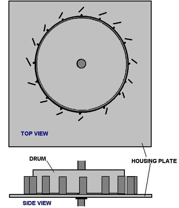 There is no need for additional housing. There is a pump needed to get the system started, and that can be mounted on the outside of the drum housing, as can the generator. The slide valve which controls the amount of liquid allowed into the drum is also mounted on the outside of the drum housing. The supporting axle pipe spins with the drum, driving the alternator generator, providing the required mains voltage AC can also be mounted on the outside of the housing. This overall arrangement produces an device which is much taller than it is wide, so a stability plate is welded to the base in order to provide that missing stability. The overall arrangement could be like this: 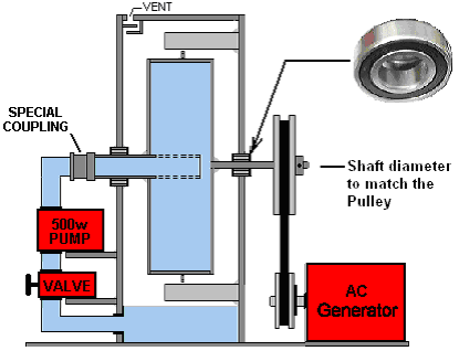 While the axle shaft can be made of two parts welded together and welded to the drum, I suggest that it is more practical to weld the incoming three-inch diameter pipe to the drum and then, choosing a bar diameter which matches the size needed for your chosen pulley wheel, that bar is welded to the other side of the drum as shown above. The part of the axle on the right is solid and provides the drive to the generator: The only item not yet mentioned is the rotating coupling shown above. This coupling needs to be able to rotate at high speed as the power output of this Donny Watts generator is exponential and increases with the square of the speed at which the drum rotates – double the speed of rotation and the output power goes up to be four times greater. This coupling could be like this: This swivelling connector has an internal ball race and it is claimed that it can operate satisfactorily at 2000 rpm, however customers say that these devices leak at speeds above 300 rpm: To get the generator operating requires the pump to be operated and so, either access to mains or alternatively access to a battery and inverter is essential. Once the generator is running, the pump can be powered by the generator. It is stated that when the speed of rotation passes one drum revolution per second, that the liquid passing through the jets causes enough vacuum inside the drum that the pump can be powered down, but it is also a possibility to leave the pump running all of the time. One of these generators with a drum of just 250 mm (10”) can output ten horsepower which is 7.5 kW and that is enough to power a household. However, people sometimes have difficulty in understanding the pressures involved. The drum which revolves is the only place that there is pressure when the generator is operating. The outer case has only two main functions, namely to support the drum axle and to act as a sump to return the liquid to the pump which feeds the liquid back to the drum to be used again. That is, the inside of the main housing is at atmospheric pressure and if you were to install baffle plates to catch the liquid passing through the jets, then it could be open at the top of the case. The concern about the rotating pipe joint leaking is not likely to be a problem because it does not occur until a speed of rotation of 300 rpm is reached. However, the Donnie Watts generator becomes self-sustaining well below that speed, and the liquid exiting through the jets starts sucking liquid in through the intake pipe. So, the intakes pipe, including the rotating pipe joint are under reduced pressure and so if the rotating joint does leak it let air leak into the pump rather than letting liquid leak out. The extra air should not be a problem unless it is really excessive as it will pass out through the jets. Just be sure to allow any excess pressure to leak out of the sump housing without letting any liquid escape. Concerns have been expressed that the pump undergoes unnecessary wear when the generator is running and the pump is not needed. If desired, the pump can have a bypass which is valve controlled like this: 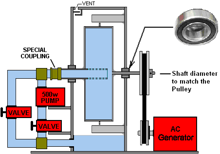 While this does require some additional piping, a valve and two T-junctions for the pipe bypass, it results in a pump which can be switched off when not needed and the new valve used as the drum speed control. Let me stress again that this is an exponential positive-feedback design which will keep accelerating until the bearings fail or the pressure inside the drum causes some form of rupture which will starve the jets of liquid, or the generator might fail due to excessive speed. While this may seem like irrelevant theory, I assure you that it isn’t. You have this generator running and powering your house and the weather is hot. You have an air-conditioning unit keeping your house cool. It draws a lot of current, but then the thermostat switches it off because your house is cool enough. This is a problem. The current draw from the generator goes down by a major amount. This makes the generator shaft much easier to spin, but the drive power from the Donnie Watts unit is now much higher than is now needed. This is not helpful, and the system is now unbalanced and the drum will speed up, spinning the generator shaft faster than it should. If you are standing there and adjust the control valve accordingly, then everything goes back to normal. But the point is that a generator of this type is fine for a fixed load, but you need to pay attention to what the electrical load is if it changes. You could put a warning alarm sensor on the drum shaft or alternatively build an automatic valve adjustment to make an automatic speed control. Let me stress again that this is an exponential positive-feedback design which will keep accelerating until the bearings fail or the pressure inside the drum causes some form of rupture which will starve the jets of liquid, or the generator might fail due to excessive speed. While this may seem like irrelevant theory, I assure you that it isn’t. You have this generator running and powering your house and the weather is hot. You have an air-conditioning unit keeping your house cool. It draws a lot of current, but then the thermostat switches it off because your house is cool enough. This is a problem. The current draw from the generator goes down by a major amount. This makes the generator shaft much easier to spin, but the drive power from the Donnie Watts unit is now much higher than is now needed. This is not helpful, and the system is now unbalanced and the drum will speed up, spinning the generator shaft faster than it should. If you are standing there and adjust the control valve accordingly, then everything goes back to normal. But the point is that a generator of this type is fine for a fixed load, but you need to pay attention to what the electrical load is if it changes. You could put a warning alarm sensor on the drum shaft or alternatively build an automatic valve adjustment to make an automatic speed control. Rick Evans, who is an American developer, has come up with an idea which overcomes the need for a swivelling pipe connection. He proposes rearranging the design slightly so that the rotating 3-inch diameter pipe which is welded to the intake side of the rotating drum just rotates in water as it is enclosed in a small container on the outside of the sump housing which supports the drum. He proposes to leave the pump connected in the circuit at all times, but powered down when the drum gets up to its self-sustaining speed. The arrangement looks like this: 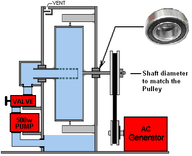 With this arrangement, the valve is still used to control the speed of the drum rotation and if the 3-inch diameter bearing supporting the intake side of the drum happens to leak a bit, then the excess liquid merely spills back into the sump where it came from in the first place. Let me stress that this is just a suggestion at this point in time as this arrangement has not yet been built and tested. As some people find this generator hard to understand, let me explain it in broad outline. The device is essentially a motor. It is a motor which is a spinning drum inside a support housing which acts as a sump. This is a self-powering motor and the faster it goes, the higher the power level which it generates. As that is a positive feedback system, the motor will keep accelerating and gaining power until it exceeds the strength of the materials use to construct it and so it breaks down. In order to prevent that happening, an adjustable valve (which is the equivalent to a large tap or fire hydrant valve) is placed in the pipe which feeds the liquid to the spinning drum. That valve acts as a manual speed control for the motor. In order to produce useful work, this motor design is used to power a separate electricity generator, using two pulley wheels and an AC generator or “alternator”, making the design a Motor/Generator. It is not easy to spin the alternator when it is supplying substantial amounts of electricity to washing machines, tumble dryers, air conditioners, heaters, stoves, TVs etc. and so the alternator acts as a brake, slowing the motor down. That doesn’t matter as the speed control valve can be opened a bit to get the speed back up to what it should be. It is important to spin the shaft of the alternator at the speed it is designed for. Spin it too slowly and it will produce a voltage which is less than mains voltage and a frequency which is less than that of the mains. Spin it too fast and the generator will produce a voltage which is higher than mains voltage and a frequency which is greater than the mains frequency. Typical design speeds for spinning the shaft of an alternator range from 1800 rpm (30 times per second) and 3000 rpm (50 times per second). Alternators are designed to produce either 110 volts at 60 cycles per second for American equipment, or 220 volts at 50 cycles per second for everybody else. This is fine IF the electrical load is constant and the speed valve is adjusted correctly. BUT we have a problem if the electrical load drops suddenly. Because the electrical current draw has dropped, the shaft of the alternator becomes much easier to spin and so it acts as far less of a brake and because the valve setting is unchanged, the motor speeds up. This is not a problem IF there is a human standing beside the generator ready to adjust the valve setting accordingly. Unfortunately, that is not convenient and worse still, many electrical appliances switch themselves on and off on a very regular basis and the basic Donnie Watts design is not able to cope with this. So, it would be very convenient if we were to make the Donnie Watts motor adjust it’s own control valve when necessary. Let’s see if we can come up with a simple system for doing that. Commercial valves are generally not suitable for this as they are either fully ON or fully OFF and are not electrically adjustable to give any intermediate setting. Also, they tend to be far too small a diameter to interest us. For a low-cost solution therefore, it appears that we need to build a simple motor speed control which we can use to give automatic speed control of the motor. At this point in time, the following is just a suggestion as it has not been built and tested in an ordinary working environment: I suggest that we might control the flow of liquid into the drum by building a control system here: 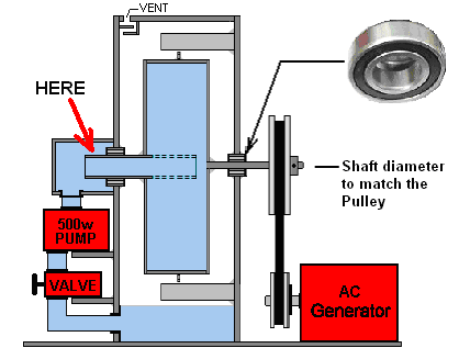 This boxed in area is something which we build and so we can choose to build it in any way that we like. Suppose we added a hinged plate which could be moved to cover the (rotating) intake pipe which feeds the drum: 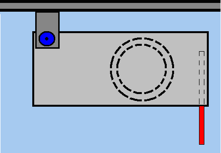 The red strip on the right is a support strip which makes sure of the plate position when it moves. However, we don’t want to block off the pipe completely as that would stop the motor spinning and that would be a nuisance, so we mount the plate so that enough water gets through the pipe to maintain a reasonable rate of rotation at even the lowest setting: 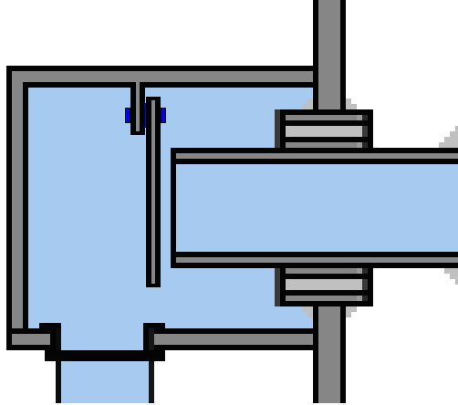 The red support strip is omitted from the above picture as it would obscure the gap which the drawing illustrates. Now, we have to find a mechanism for moving the plate. I suggest a small DC motor with a worm gear on the shaft. This has the advantage that when the motor is not powered, it holds its current position and is not affected by the thing it is driving:  And while it is generally expected that such a motor would drive a rotating shaft it can drive a rack:  And that could be used to rotate the plate in a very precise and secure way: 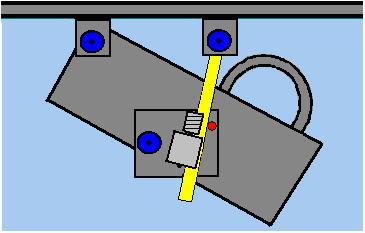 However, some people are appalled at the idea of submerging a motor in a liquid (quite possibly cooking oil) and so perhaps a different way of moving the plate could be used, one which keeps the motor outside the liquid. Irrespective of what arrangement is used to move the plate, a control signal is needed. There are various ways of doing this. One of the easiest is to attach a plastic disc to the drive shaft and embed two or more magnets in it. Those magnets can be the input signal to a rev counter or “tachometer” which can measure the speed of the shaft rotation and output a signal which is proportional to that speed. The output shaft rotation will be at 15 or 25 revs per second if the drum pulley wheel diameter is twice that of the alternator drive wheel. The sensor for picking up the output shaft rotation speed could be a Hall-effect sensor: 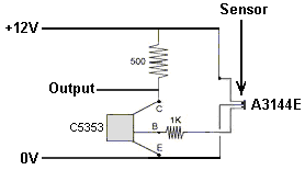 However, please understand clearly that the Donnie Watts generator is perfectly viable without automated operation. For example, if it is cold outside and you need to heat your living space, then switching on a two kilowatt or three kilowatt heater and some lights, allows you to set the intake valve correctly so that they operate continuously. Provided that the heater is not thermostat controlled (or if it is, then it’s heat setting is set so high that it will never be reached, or the heater wired to ignore the thermostat) then the electrical load is constant and the Donnie Watts heater setting will always be correct. In passing, a heater which is on continuously raises the temperature of a room to a very considerable degree as the hours and days go by. Doing that is generally too expensive if you have to pay for the electricity, but with the Donnie Watts generator there is no direct charge for the electricity. When setting up the generator initially, you connect a voltmeter across the output of the generator and then adjust the valve setting so that the generator just reaches the voltage that the manufacturer of the alternator specifies for your particular alternator. For home builders, it would probably be easier to use a 16-sided shape rather than a circular disc:  Apart from being all straight-side cuts, there is the advantage that the plates which form the circumference of the drum can become drilling points for a system which is more simple than using pipe nozzles:  The single drill hole in the middle of the circumference wall of the drum then acts as a jet and using the template to get the drill bit angle the same every time, produces correctly angled water jets. Some people feel that they would prefer to have some more detailed information, so the following are some very basic details for constructing a generator with a 450 mm (18 inch) diameter drum using straight edges. To make the first drum side we start with a square piece of 3 mm thick mild steel 470 mm x 470 mm.  Draw diagonals from the corners to establish where the centre of the square is, then draw vertical and horizontal lines, like this:  Measure 225 mm from the centre point, out along each line and mark each of those points. Then, connect those points to make an even octagon:  Next, mark the central point of each of the eight sloping lines and draw a line from the central point through each of these new points:  Mark 225 mm from the central point out along each of these new lines and then connect these points to form the 450 mm diameter 16-sided drum side:  Then cut along these outside lines to form the first side of the drum: Clamp this side to another piece of 3 mm thick mild steel and mark carefully around it to get the shape and size of the second side of the drum. Cut around this new side and draw some diagonals to establish the centre point. One of these two drum plates needs to have the 3-inch (75 mm) intake pipe installed as an axle. You could get a local steel fabrication shop to drill the hole for you. Alternatively, you could mark the exact position and size and drill a ring of small holes around the circumference and with a small cutting blade in the angle grinder, cut between the holes and then using a grinding disc in a power drill, smooth out the unevenness between the holes to give a reasonable quality hole accurately positioned. Remember to use goggles for both cutting and smoothing. Another way would be to rent a plasma cutter and air compressor for a morning and use that to cut an exact hole. Having got the exactly positioned hole in the drum side plate, it needs to be welded in place. For that, these magnetic angles are enormously helpful:  This is because they are low cost, grip the plate and pipe very strongly and make a perfect 90-degree angle. Using four of these magnetic clamps holds the pipe securely and accurately. Remember that the moment a weld is made on one side of the drum plate, the other side of the drum plate needs to be welded immediately and both allowed to cool as slowly as possible to avoid heat shrinkage pulling the pipe out of its alignment with the drum plate. Remember that the drum plate will be hot enough to burn you even if the weld only took a split second to make, so take care. In other words, if the pipe is vertical, then almost simultaneous welds need to be made on the top of the drum plate and on the underside of the drum plate. The thicker the steel, the easier it is to weld without problems and so welding the pipe is straightforward. It takes a great deal of skill to weld steel sheet of 1 mm thickness without tearing a hole in the sheet, but thankfully, that is not something which you need to do with this design. Having tack-welded the pipe carefully and quickly on both sides, using welds only 6 mm or so long, and having waited for those welds to cool down fully, make two additional tack welds at 180 degrees away from the first two, and then two more pairs so as to have a weld every 90 degrees around the pipe. Then the welding all around the pipe is completed welding only very short lengths in opposing pairs and letting the welds to cool before making the next weld. A cheap workmate like this:  makes a good support for this work and it allows the pipe to be gripped securely while the drum plate is resting horizontally on the bench. If you feel that an open 3-inch (75 mm) diameter pipe is not sufficient to get the liquid into the drum, then make as many openings (drill holes or angle grinder slits) as you consider necessary. Mild steel 3 mm thick can be supplied in 150 mm wide strips. One of those would reduce the amount of steel cutting needed to complete the drum as it is needed for the internal channels and for the circumference wall of the drum:  As the drum diameter is 450 mm and 150 mm is left around the centre and 50 mm is left at each side, the eight internal walls need to be only 225 – 75 – 50 = 100 mm (4 inches) long, which means that they can be cut from the 150 mm wide strip. As we want to use the width of the 150 mm strip to make the sixteen circumference strips, measure the exact width of the strip supplied to confirm that it is 150 mm wide. I have never been supplied a strip which was not accurately 150 mm wide, but check carefully to make sure that your strip is exactly 150 mm wide and adjust the measurements slightly if it isn’t. Ideally, the strip is exactly 150 mm wide and so the inner walls need to be 144 mm wide and 150 mm long:  So each strip can be made with a single cut, chopping off a 144 mm long strip of the 150 mm wide strip. You start by welding these narrower strips as the vertical walls (and be very sure that the shorter plate measurement is the one which is vertical to the side of the drum!):  Use the magnetic clamps to hold each plate vertical when positioning and tack welding it. Complete the welding of these eight plates, remembering to take it slowly, remembering to always use simultaneously opposing welds and allowing each weld to cool naturally. The next step is to attach the second side of the drum. The really important thing here is to align the second side exactly and the magnetic angles are helpful here as well. Measure the straight edges which form the circumference to your drum and cut two 150 mm strips to that exact length. Place the first drum side with it’s welded partitions, horizontally on the workmate and attach one magnetic brace to it, positioning the magnet exactly at the edge of the disc, half way along one straight edge. Do that 90-degrees away with a second magnet. Attach one of your edging strips to each magnet, standing them straight up vertically, then slide the second side on top, aligning a straight edge with a straight edge on the lower drum side. Use additional magnetic braces to attach the upper drum side to each of the two edging pieces attached to the lower drum side. Make sure that all four magnets are fully touching the drum sides and the edging pieces. Go around the whole drum, using a setsquare to confirm that the two drum sides match exactly and be very sure that the flat edges match exactly. Remember that once you make the first tack weld on the second drum side, that is it, and you have no realistic chance to change the positioning. Once you are satisfied that the second drum side is positioned exactly right, make two opposing tack welds on the second (upper) drum side like this:  These welds are made upwards, so be sure you are wearing good strong gloves as getting molten metal on bare skin is not a pleasant experience! Then make two more opposing tack welds like this:  You can then turn the drum over so that all following welding is downwards and you are not liable to get hot metal coming at your hands. There is room to weld inside the drum as the pieces forming the channel walls are only 150 mm long and there is 144 mm of clearance between the drum sides. These eight short pieces hold the drum sides securely and give the drum major strength. Strictly speaking, the above diagrams should show 16-sided sides rather than circles. We come now to attaching strips to the sides of the drum to form the circumference. Remove the magnets and alignment side strips and turn the drum sideways and clamp it in the workmate so that the drum edge is facing upwards and so is easy to work with. Take the two edging pieces already cut, and weld them to the drum in opposite positions around the drum:  The welds can be made inside the drum if you wish. Two more circumference pieces are then measured carefully, cut and welded like this:  Then four more like this:  This is where it becomes interesting. The final plates need to be measured very accurately and they will be welded in place like this:  The V-notch between the plates is very important as it is where the nozzle jets will be drilled: 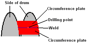  It may be necessary to lower the next circumference plate just opposite the jet exit using a grinding tool so that it does not interfere with the jet of liquid leaving the drum:  So, after all that effort, you now have a strong and secure drum, but it only has the 3-inch diameter inlet pipe attached and we need the axle support bar on the other side of the drum. What diameter should it be? I don’t know, because it needs to have a pulley mounted on it. I would expect it to be about 25 mm (1-inch) in diameter but you need to search suppliers for pulleys and buy two, one for the drum and one to match the drive shaft diameter of your alternator. Obviously, the two pulleys need to work with the same drive belt. Ideally, the drum pulley should be two or thee times the diameter of the alternator pulley. In fact, any ratio up to say, five times would be good as the working output of the alternator will be reached at lower drum revolutions and that would give smoother running if the drum construction is not perfect. So, we have identified what shaft diameter is needed for the drum output and we have purchased a mild steel bar of that diameter. The centre point of the second drum side is marked. If you have cleverly welded it on the inside of the drum, then mark the diagonals to get the centre point. Check it by clamping the 3-inch pipe bearing in the workmate, placing the drum inlet pipe in it and spinning the drum. The centre point should appear stationary when the drum spins. Holding a felt-tipped pen stationary, mark a small circle by touching the drum close to the centre – say about 30 mm in diameter. That is where the pulley bar needs to be welded. Use the four magnetic clamps to position the bar in the middle of the circle with the clamps at 90-degree angles to each other. Spin the drum again to make sure that the bar does not appear to move. If it does, then correct the position until the bar seems motionless. Then tack weld between the magnets. Unfortunately, heat destroys magnets and so welding so close to the magnets is liable to destroy them – thankfully, they are cheap to replace. Now that we have completed the drum, we need to make the support housing which also acts as a sump for the liquid which has passed through the drum. In passing, while the Clem engine used cooking oil as the liquid because the Clem engine generates a good deal of heat, some people suggest using transmission fluid in the Donnie Watts design, primarily so that it lubricates everything which it passes through. However, transmission fluid is very expensive so it seems much more sensible to use cooking oil which is maybe eight times cheaper than transmission fluid. The container which acts as a sump can just be a rectangular box. It is specified that there should be 75 mm clearance on both side of the drum which is 450 mm + 75 mm + 75 mm = 600 mm wide. The sump is to have an additional 200 mm depth and with the 75 mm at the top and the 450 mm diameter of the drum, makes a front and back panel size of 725 x 600 mm. The sides would need to be about 300 mm wide: 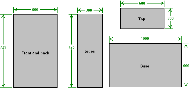 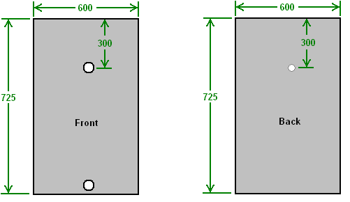 The next step is to construct the baffle plates to catch the jets of liquid coming out of the nozzles of the drum. First, a hole is created in the front panel and the bearing attached. The bearing will be the best 75 mm diameter bearing which will fit your intake pipe and mount securely to the front panel:  With the bearing fitted, place the front panel on the workmate and feed the drum’s intake pipe into the bearing. This gives you a flat, horizontal surface with the drum in it’s exact position. Clamp the drum in place so that it can’t move. One of the magnet clamps is now used to position, and mark the position of the first baffle. With the drum fixed in place, mark the position of the matching fifteen other baffle plates. Unclamp and remove the drum so that there is a clear unencumbered work area. Using just one magnetic clamp, position each baffle plate and tack weld it in position with a tack weld on the drum side and an immediate matching tack weld on the side away from the drum – remember that we need matching welds to stop the cooling weld pulling the baffle plate away from the vertical.  Next, put the drum back again and give it a spin to make quite sure that the drum clears all of the baffle plates. If you are enthusiastic, you could use 32 baffle plates rather than the sixteen shown. I seriously doubt the spacing specified for the housing. The liquid squirts through the drum "nozzles" and hits the baffle plates. But then, where does it go? It has lost it's momentum and will just fall under gravity. Some will fall on to the drum which will hurl it off on to the wall where it will fall down into the sump. Part will fall clear of the drum and will fall down the side of the housing. So, why the gap? 75 mm should be easily enough to allow that to happen no matter what the drum diameter is. Five millimeters of space outside the baffles should actually be quite enough. The physical size and shape of the pump is not important as it is located outside the sump housing. I have been asked what is the minimum pump size, but I don’t know, the most I can say is that Donnie Watts specified a 500 watt pump for his four-foot diameter drum. Please understand that I have never built or even seen a Donnie Watts generator. I believe that it will work exactly as specified (especially since the very similar Clem Motor worked well) but I can’t guarantee that it will. In passing, if the arrangement where there is a pump bypass pipe and valve, then one pump could be used to start a whole row of Donnie Watts generators by disconnecting the pump from each as soon as it is running properly. Of course, in that case, the pump valve needs to be between the drum and the pump to enclose the sump when the pump is removed. Purely On and Off valves are not expensive, even in 3-inch diameter:  It appears that this valve is either fully On or fully Off. There are valves which claim to be fully adjustable under electronic control but they have still to be investigated and assessed. So, for the moment, assume that the generator will be run under constant load and just construct the box surrounding the drum intake pipe as 300 x 300 x 150 mm in size and with a removable 300 x 300 mm side sealed with a plastic or rubber gasket. If you feel that a generator which is restricted to a fixed load output is really not all that useful, then think again. Consider using it to power an Elmer Grimes water supply system. The US patent 2,996,897 (22 Aug 1961) is more than fifty years old and it describes a system which can produce drinking quality pure water. It is effectively an outdoor refrigerator. A series of cone-shaped metal panels are stacked together vertically to save space. Each cone has pipes inside it which pass the cooling fluid through the cones, ensuring that they are always at low temperature. In the same way that a cold drink gets water droplets on the outside of the glass, the cones get water droplets forming on them all the time. A wiper arm like a windscreen wiper on a car then brushes those droplets off, with the wiper arm rotating around the cones continuously, rather than backwards and forwards as a car wiper blade does. This produces a continuous stream of fresh water coming off the cones. Unless there is some good reason why not to, the cones are mounted in a raised position so that gravity can be used to direct the water flow to where it needs to end up. Cones are used as they have a greater surface area than a flat plate of the same diameter would have, and the downward slope of the cone helps the water droplets flow off the cone surfaces. Top view:  Side view:  One of these Grimes systems produces enough water to support a ranch in Texas during a drought, and it could be powered indefinitely by a Donnie Watts generator. Think of the effect one would have on a village which has only access to polluted water (especially if you don’t know the technology of colloidal silver). As it is probably not necessary to produce drinking water all the time, the generator could power electrical cooking in area where firewood is getting scarce, charge mobile phones, power TVs, power fans, refrigerators, etc. The inside of the sump housing is an unpressurised and very wet area. We don’t want any oil leaking out through the drive shaft bearing, so providing a steel umbrella would be a good idea: For this, two triangles of steel are cut and then welded so that most oil landing on them will run off without reaching the bearing: 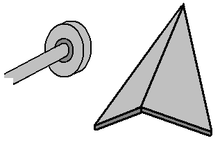 Some people may prefer to use commercially constructed components instead of constructing an adjustable flap for the 3-inch diameter rotating intake pipe to the drum. Well, let’s see if we can come up with a different method of low-cost automatic flow control. For the system to be automatic I suggest that we could use electrically operated valves which can then be governed by a control circuit. The vast majority of such low-cost valves are only half-inch diameter made for central heating systems, and they are closed unless fed with power to open them. I would suggest the following valves as being possible:  This three-quarter inch diameter brass valve costs about £8 and at about the same price we have a plastic one-inch diameter valve:  Half inch plastic versions are available for about £4 but my preference is for the brass three-quarter inch diameter version. However, we can get variable control by using a row of these valves to restrict flow. For this, we use a second liquid filled box like this: 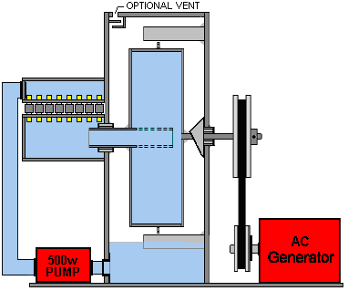 This row of say, ten valves allows ten different flow settings when the valves are switched on or off by the control circuit and there is the added advantage that if the control circuit is powered via the alternator output and there is a major problem where the drive belt snaps or there is any other major fault which removes the alternator drag from the output shaft, then all valves will automatically shut down and block the flow due to lack of voltage to keep them open. The arrangement could be like this: 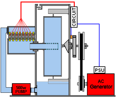 The most direct way of determining the speed of the output shaft is to connect a disc to the shaft and use a sensor to detect how often a magnet in the disc passes by. A rev counter circuit then monitors the shaft speed and switches off valves progressively if the shaft starts to rotate too fast. While the diagram above shows the most secure way to assess the speed of rotation of the generator, for most people it is more convenient to skip as much construction work as possible. So, a way which skips the need for an additional rotor disc and sensor is attractive. For that we can measure the output of the alternator rather than the direct speed of the generator axle. The alternator is an alternating current generator. If you spin the drive shaft of the alternator at it’s design speed then mains voltage is produced. If the shaft is spun faster than it is supposed to be, then a higher voltage is produced. If the shaft is spun slower than it’s design speed, then the output voltage is less than the mains voltage. We can therefore use the voltage of the generator’s output to control the switching of the row of valves, and the design then becomes this: 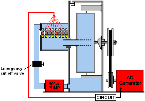 With this arrangement, if the drive belt were to break or the alternator were to develop a serious fault, then the circuit voltage would drop off and as a result, the circuit would no longer supply current to the open valves and they all would close, shutting off the generator which is exactly what is needed. Now, all that is needed is a simple circuit to control the valves. Please understand clearly that I have never been trained in electronics and so I am only self-taught, so feel completely free to consult an expert to provide you with a better circuit.. The three quarters of an inch brass valve has a 20 mm opening and opens if fed 300 milliamps of current at 12 volts. That is 3.6 watts of power for each valve or just 36 watts for all ten valves. The alternator produces mains voltage so we will drop that down to around 12 volts both for safety sake and to make the circuit components cheaper. To drop the voltage down we use a simple power supply comprising of a 3-amp mains transformer to lower the voltage, a diode bridge to convert the output into pulsing DC and a capacitor to smooth out the pulsing: 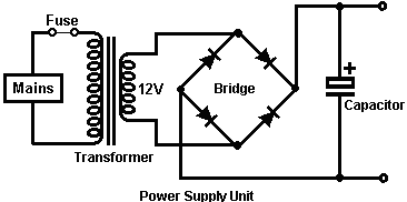 As with all circuits, and especially mains circuits, we install a fuse or circuit breaker as the first component, and we insulate all metal components to make sure that we don’t accidentally touch them and get a nasty shock. Once the voltage is down to 12 volts the circuit is no more dangerous than a 12 volt car battery and it is not necessary to insulate everything. The fuse is a 3-amp fuse. This circuit is deliberately not self-adjusting as we want to use it to detect voltage differences coming in from the alternator which is marked “Mains” in the diagrams. The most important thing is to detect a rise in voltage as that indicates that the generator is starting to rotate too fast and so we want to switch off one or more valves. The circuit for each valve is the same as for all of the others although the adjustment of each circuit is slightly different so that the valves switch off at slightly different voltages. The switching circuit which we will use is called an “operational amplifier” and thankfully that whole circuit comes ready made in a standard chip. For example, the very cheap LM358 chip has two separate “op-amp” circuits in it:  If we connect an LM358 into the circuit we get this:  If the voltage at pin 3 exceeds the voltage at pin 2 then the output on pin 1 will be high (about 10 volts) otherwise the voltage on pin 1 will be low. We will us the high voltage on pin 1 to switch on one of the valves and we will use a high-power high-gain transistor like the TIP132 to do this:  The TIP132 can handle 100 volts, 8 amps and has a gain of 1000, so if it is passing 330 milliamps through the valve winding, then it will need a base current of 0.3 milliamps. That current flows through the resistor “R” which has about 10 volts across it. Resistance = Volts / Amps or 10 / 0.0003 amps which is 33,333 ohms or 33K. However, we will increase the base current by a factor of 3 and use a 10K resistor:  Now we need to get the LM358 to switch off, causing the voltage on pin 1 to drop low, starving the TIP132 of base current and cutting the power to the coil of the valve. For that, we need the voltage on pin 2 to rise above the voltage on pin 3 and we want that to happen if the power supply voltage rises. So, if we connect a multi-turn10K preset resistor across the power supply and feed it to pin 2, then we can set it so that the op-amp triggers with a rise in voltage. A resistor of that type looks like this:  And the circuit becomes:  Now the last step is to provide a reference voltage which does not change if the power supply voltage increases. The approved way is to use a zener diode with a resistor in series with it and in theory, the voltage drop across the zener diode is a reliable reference voltage. I have not found that arrangement to work at all well, so I suggest using ordinary diodes such as the 1N5408 instead, like this:  This arrangement gives about 10 milliamps flowing through the diode chain and some 2.75 volts are generated across the diodes. That voltage does not alter appreciably if the power supply voltage increases. The second op-amp in the LM5408 chip can be used to control the next valve. Pins 4 and 8 are already connected to the power lines, but what was pin 1 is now pin 7, what was pin 2 is now pin 6 and what was pin 3 is now pin 5. The circuit is set up using a bench power supply. Measure the voltage of the power supply powered by the Donnie Watts alternator and then disconnect it. Connect the bench supply in place of the alternator supply and set the voltage to exactly the same value. All op-amps are connected to the four diode reference voltage point. Let’s say that we want the valves to drop out at every 5-volt increase of the mains voltage. If it is a 240 volt mains supply, then the transformer drops that down to 12 volts which makes the change 20 times smaller, so the power supply voltage will go up by only 5 / 20 volts which is only one quarter of one volt. So you adjust the bench power supply up by a quarter of a volt and adjust the first variable resistor so that the first valve shuts off. Lowering the bench supply voltage by that quarter of a volt should have the valve clicking open again. This is repeated with all of the valves so that the second valve drops shut at half a volt higher voltage. The third valve drops closed at three quarters of a volt increase over the original voltage, and so on. When starting the Donnie Watts generator you need the valves open and so a 12V source has to be applied to the valves. Make sure you do that through a press button switch and not a toggle switch because you could easily forget to switch the toggle switch off after the system gets up to speed. The Magnet Pendulum. At the present time, there is a short video clip on YouTube, showing a pendulum which has been running unaided for two years: video and which uses both gravity and magnetism to keep going. The device is installed in a case with transparent sides:  The pendulum itself looks rather like a sledgehammer due to it's rigid shaft and the additional magnets mounted on the weight. The above picture shows the pendulum at the end of it's swing to the right and the picture below, in it's extreme left hand swing position: 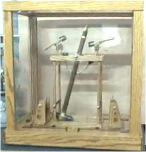 Which indicates the swing covers a fairly short distance. Mounted near the top of the pendulum, there are two pivoted arms which look quite like microphones, due to having large magnets mounted on their innermost ends:  The device operates like this: The pendulum swings to the right and as it does so, it raises a magnet attached to the pendulum shaft by a curved silver arm: 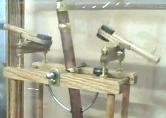 Presumably, the arm is curved to avoid the constructional complications at the pendulum pivot which would be caused by a straight mounting arm attached to the pendulum shaft. The rising magnet attached to the pendulum pushes the magnet end of the rocker arm upwards even though it does not come close to it. The rocker arm is used to raise and lower a plate which has a magnet mounted in it. The raising and lowering is achieved by having two cords attached to the end of the rocker arm and their other ends attached to the two upper corners of the moving plate: 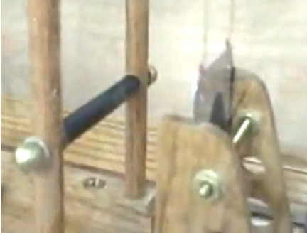 The plate slides in two slots in the support housing and the plate movement is relatively small: 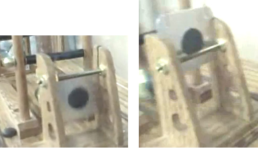 The tipping up of the lever arm drops the plate down as the pendulum approaches the plate. This introduces a magnetic braking effect where some of the momentum of the pendulum weight is stored in the opposing magnetic fields of the pendulum magnets and the plate magnet. This brakes the pendulum movement and gives it a magnetic push on its opposite swing, sustaining it's swinging day after day after day. This is a clever arrangement and the device on display has been built to a very high standard of construction. It does not appear to have any additional energy take off, but seems quite likely that air-core coils could be used along the swing path to generate electrical power. The arrangement appears so close to John Bedini's pendulum battery charger that it may well be possible to use a pendulum of this type to charge batteries just as John does. While this looks like a very simple device, it is highly likely that it requires exact adjustment of the length of the lever arms, the magnetic gap sizes in relation to the strength of the magnets, etc. etc. Repeated small adjustments are probably needed to get the device operating smoothly and sustaining the pendulum swing. All in all though, it is a very interesting device. Gravitational Effects. We are all familiar with the effects of gravity. If you drop something, it falls downwards. Engineers and scientists are usually of the opinion that useful work cannot be performed on a continuous basis from gravity, as, they point out, when a weight falls and converts it’s “potential energy” into useful work, you then have to put in just as much work to raise the weight up again to its starting point. While this appears to be a sound analysis of the situation, it is not actually true. Some people claim that a gravity-powered device is impossible because, they say that it would be a “perpetual motion” machine, and they say, perpetual motion is impossible. In actual fact, perpetual motion is not impossible as the argument on it being impossible is based on calculations which assume that the object in question is part of a “closed” system, while in reality, it is most unlikely that any system in the universe is actually a “closed” system, since everything is immersed in a massive sea of energy called the “zero-point energy field”. But that aside, let us examine the actual situation. Johann Bessler made a fully working gravity wheel in 1712. A 300 pound (136 Kg) wheel which he demonstrated lifting a 70 pound weight through a distance of 80 feet, demonstrating an excess power of 5,600 foot-pounds. Considering the low level of technology at that time, there would appear to be very little scope for that demonstration to be a fake. If it were a fake, then the fake itself would have been a most impressive achievement. However, Bessler acted in the same way as most inventors, and demanded that somebody would have to pay him a very large amount of money for the secret of how his gravity wheel worked. In common with the present day, there were no takers and Bessler took the details of his design to the grave with him. Not exactly an ideal situation for the rest of us. However, the main argument against the possibility of a working gravity wheel is the idea that as gravity appears to exert a direct force in the direction of the earth, it therefore cannot be used to perform any useful work, especially since the efficiency of any device will be less than 100%. While it is certainly agreed that the efficiency of any wheel will be less than 100% as friction will definitely be a factor, it does not necessarily follow that a successful gravity wheel cannot be constructed. Let us apply a little common sense to the problem and see what results. If we have a see-saw arrangement, where the device is exactly balanced, with the same length of a strong plank on each side of the pivot point, like this: 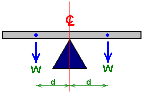 It balances because the weight of the plank (“W”) to the left of the support point tries to make the plank tip over in a counter-clockwise direction, while exactly the same weight (“W”) tries to tip it over in a clockwise direction. Both turning forces are d times W and as they match exactly, the plank does not move. The turning force (d times W) is called the “torque”, and if we alter the arrangement by placing unequal weights on the plank, then the beam will tip over in the direction of the heavier side: 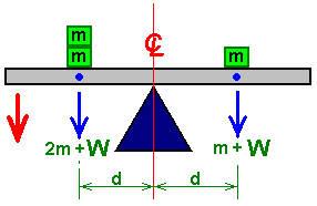 With this unequal loading, the beam will tip down on the left hand side, as indicated by the red arrow. This seems like a very simple thing, but it is a very important fact. Let me point out what happens here. As soon as the weight on one side of the pivot is bigger than the weight on the other side (both weights being an equal distance from the pivot point), then the heavy plank starts to move. Why does it move? Because gravity is pushing the weights downwards. One other point is that the distance from the pivot point is also important. If the added weights “m” are equal but placed at different distances from the pivot point, then the plank will also tip over: 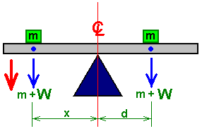 This is because the larger lever arm “x” makes the left hand weight “m” have more influence than the identical weight “m” on the right hand side. Do you feel that these facts are just too simple for anyone to really bother with? Well, they form the basis of devices which can provide real power to do real work, with no need for electronics or batteries. The following suggestions for practical systems are put forward for you to consider, and if you are interested enough test out. However, if you decide to attempt to build anything shown here, please understand that you do so entirely at your own risk. In simple terms, if you drop a heavy weight on your toe, while other people may well be sympathetic, nobody else is liable or responsible for your injury - you need to be more careful in the future ! Let me stress it again, this document is for information purposes only.  Mikhail Dmitriev. Mikhail is a Russian experimenter who has worked for many years developing and testing gravity-powered devices. His persistence has paid off and he has been very successful. His work is shown on Stirling Allan’s web site http://peswiki.com where there are videos and photographs of several of his prototypes. It is envisaged that large versions which generate 6 to 12 kilowatts of excess power will become available for purchase in 2011. Each of his various designs is based on the principle of having weights attached to a wheel and arranging for those weights to be offset outwards when falling and offset inwards when rising. Because of the different lever arms involved, that gives a force imbalance which causes the wheel to rotate continuously and if the weights are of a considerable size, then the rotation is powerful and can be used to generate electrical energy. In order to arrange for the weights to be offset as the wheel goes around, each weight is suspended on a pivoted arm:  For the device to operate as required, that suspension arm needs to be moved to (say) the right when falling and be centred or deflected to the right when rising. Mikhail has chosen to use a small amount of electrical power to make this happen, because the energy provided by gravity in turning the wheel far outweighs the small electrical input needed to make the wheel rotate. Several mechanisms for making this happen have been tested as you can see from Stirling’s presentation. One method is to push the lever arms to the right with a simple rotating disc which has deflector arms attached to it: 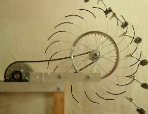 After being given the sideways push, each weight stays off centre until it reaches the bottom of it’s travel. Please remember that while the weights show here are tiny, a full-size working device will have weights which weight a total of perhaps 130 kilograms and the forces involved are then large. The picture above is a little difficult to make out as the rotating disc is transparent and the support for the rotating arms is also transparent. The horizontal metal arm is there to support the transparent panel on which the ‘arms wheel’ bearing is mounted. An alternative method is to use a small motor which drives the arms directly as shown here: 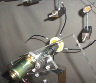 Each weight is held rigidly and so when the motor arm presses against it, the lever arm is pushed out sideways without the weight twisting away from the motor arm. These prototype weights are not heavy, but when a working unit is being built they will have considerable weight, so to get a well balanced arrangement, it might be advisable to have weights on both sides of the wheel so that there is no offset axial load placed on the shaft which supports the wheel: 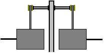 Mikhail’s arrangement works well when it relies on the swinging movement of the weights to keep them off centre during the time when they are falling and you can watch a video of that happening. However, it makes one wonder if it would not be possible to arrange for this movement without the need for a motor, although using a motor is a very clever and sensible method of ensuring rotational power. Perhaps if two stationary deflectors were used, one to keep the weights out to the right when falling and one to keep them out to the right when rising, a viable system might be created. Perhaps something like this: 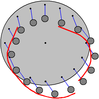 The Veljko Milkovic Pendulum / Lever system. The concept that it is not possible to have excess power from a purely mechanical device is clearly wrong as has recently been shown by Veljko Milkovic at his web site where his two-stage pendulum/lever system shows a COP = 12 output of excess energy. COP stands for “Coefficient Of Performance” which is a quantity calculated by diving the output power by the input power which the operator has to provide to make the system work. Please note that we are talking about power levels and not efficiency. It is not possible to have a system efficiency greater than 100% and it is almost impossible to achieve that 100% level. Here is Veljko’s diagram of his very successful lever / pendulum system: 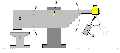 Here, the beam 2 is very much heavier than the pendulum weight 4. But, when the pendulum is set swinging by a slight push, the beam 2 strikes down on anvil 1 with considerable force, certainly much greater force than was needed to make the pendulum swing. As there is excess energy, there appears to be no reason why it should not be made self-sustaining by feeding back some of the excess energy to maintain the movement. A very simple modification to do this could be: 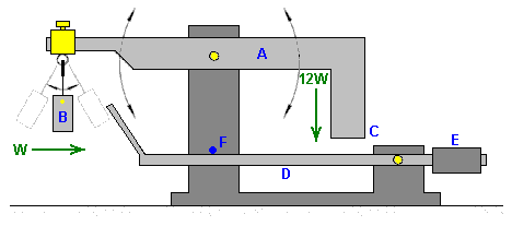 Here, the main beam A, is exactly balanced when weight B is hanging motionless in it’s “at-rest” position. When weight B is set swinging, it causes beam A to oscillate, providing much greater power at point C due to the much greater mass of beam A. If an additional, lightweight beam D is provided and counterbalanced by weight E, so that it has a very light upward pressure on its movement stop F, then the operation should be self-sustaining. For this, the positions are adjusted so that when point C moves to its lowest point, it just nudges beam D slightly downwards. At this moment in time, weight B is at its closest to point C and about to start swinging away to the left again. Beam D being nudged downwards causes its tip to push weight B just enough to maintain its swinging. If weight B has a mass of “W” then point C of beam A has a downward thrust of 12W on Veljko’s working model. As the energy required to move beam D slightly is quite small, the majority of the 12W thrust remains for doing additional useful work such as operating a pump. Other designs. Stirling Allen reports on Bobby Amarasingam’s design which has 12 kilowatts of excess power: here Also reported by Stirling is the Smith-Caggiano gravity/momentum/centrifugal-force generator design. The report is here Another of Stirling’s reports is on the Chalkalis Gravity Wheel which can be seen here Buoyancy While we are aware of buoyancy being used to convert wave power into electricity, we seem to neglect the idea of using the very powerful buoyancy forces (caused by gravity) as a direct tool at locations away from the sea. This is definitely a mistake because serious levels of power can be generated from such a system. One such system is: The “Hidro” Self-Powered Generator of James Kwok. This design demonstrates yet again, the practical nature of drawing large quantities of energy from the local environment. Commercial versions are offered in three standard sizes: 50 kilowatt, 250 kilowatt and 1 megawatt and licensing partners are being sought. This generator which James has designed can be seen at the Panacea-bocaf.org web site www.panacea-bocaf.org and on James’ own web site www.hidroonline.com both of which have video clips explaining how the design works. The method is based on different pressures at different depths of water, gravity, and on the buoyancy of air-filled containers. The system does not rely on wind, weather, sunlight, fuel of any type, and it can operate all the time, day or night, without causing any kind of pollution or hazard. This particular design calls for a water-filled structure of some height, a source of compressed air and a pulley system, and without wishing to be in any way critical, it seems rather more complicated than it needs to be. If, unlike James, you have not done the mathematics for the system, you would assume that the amount of power generated by a system like this would be less than the amount of power needed to make it operate. However, that is definitely very far from reality as considerable excess power is gained through the natural forces of the local environment which make the system operate. Part of the patent application which James made is shown here: HYDRODYNAMIC ENERGY GENERATION SYSTEM  Fig.1 is a cross-sectional view of an embodiment of the energy generation system of the present invention. Here, the energy generation system 10 comprises a vessel 11 in the form of a water tank and a shaft 12 which can rotate about it’s longitudinal axis. The shaft 12 is provided with a helical screw groove 13 and is connected at it’s lower end to a bearing 16 which allows it to rotate freely about its longitudinal axis. The upper end of the shaft is connected to a generator 17 which is a flywheel system. The rotational energy of shaft 12 may be transferred to the generator through a ratchet-cog system 20. A buoyant inflatable capsule 14 is provided along with its guiding mechanism 15 which is in the form of a wire or pole to assist in the smooth vertical movement of buoy 14. There is a first air reservoir 18 located in a lower portion of the vessel 11 and a second air reservoir 19 located in an upper portion of the vessel 11. The first reservoir 18 draws air from the atmosphere, in through air intake port 21. Once the pressure in the first reservoir has reached a predetermined value, a piston 22 is actuated, forcing air through hose 23 into the buoyant capsule 14, which, when inflated, begins to move upwards through water tank 11, as the buoy 14 has become less dense than the fluid 25 (such as fresh water or saltwater) in tank 11. This in turn causes rotation of shaft 12, and activation of the power generator 17, thereby generating power. When buoy 14 reaches the upper limit of its travel, the air in the buoy may be forced to flow through a second hose 24 and into the second air reservoir 19. When air is removed from the buoy it moves downwards through vessel 11 under gravity and with the assistance of ballast (not shown). The downward movement of buoy 14, causes rotation of the shaft 12, which drives the generator 17, thereby generating power. Air stored in the second reservoir 19 may be vented to the atmosphere through a vent 26 if the pressure in the second reservoir 19 becomes too high. Alternatively, air may flow from the second reservoir 19 into the first reservoir 18 through a third hose 27 so that less air must be drawn into the first reservoir 18 when buoy 14 reaches the lower limit of its travel and must once again be inflated with air from the first reservoir 18. The hoses 23, 24 and 27 are provided with non-return valves 28 to ensure that air will flow in only one direction through the system 10. Vessel 11 may be provided with ventilation 29 as required and it may also be provided with access stairs 30 and an access platform 31 so that maintenance may be carried out as required. The system may also be provided with a solar energy collection device 32 to generate at least a portion of the energy required to drive piston 22 and the non-return valves 28. Energy produced by the solar energy collection device 32 may also be used to power a light or beacon 33 to indicate the location of the system 10  Fig.2 shows one arrangement for buoy 14 comprising an inflatable capsule 34. This figure illustrates the shape of the walls of the inflatable capsule 34 when inflated 35 and when deflated 36. Air passes into capsule 34 through hose 23 and exits from the capsule through hose 24. The buoy 14 also has a sleeve 37 attached to it. This sleeve has projections which engage with the helical groove 13 of shaft 12, thereby causing rotation of the shaft when the buoy moves relative to shaft 12. Sleeve 37 is provided with ballast 38, such as stainless steel weights that assist in the downward movement of the buoy when it is deflated. Buoy 14 is attached to a guide pole 15 and the buoy has a pair of arms 39 which slide on the guiding pole 15 and assist in the smooth vertical movement of the buoy  Fig.3 shows one version of the first air reservoir 18. Air is drawn into reservoir 18 through air intake 21. The reservoir includes a piston 22 associated with a spring 40, the piston 22 being provided with seals 41 to prevent leakage of air. When pressure, such as hydrostatic pressure, is applied in the direction of arrow 42, the piston moves to the left of the reservoir 18 compressing spring 40 and forcing air out through outlet 43. A motor 44 is provided to reverse the movement of the piston 22. Reservoir 18 may be fixed to the floor of the vessel. 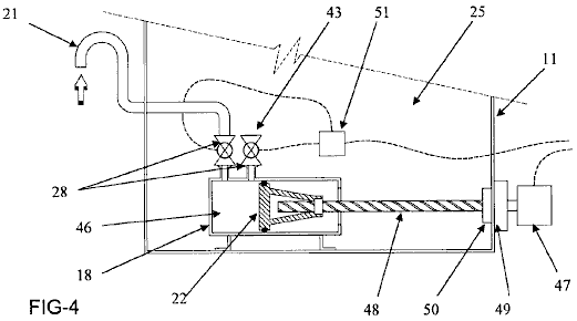 An alternative construction of the first air reservoir 18 is shown in Fig.4. In this embodiment, reservoir 18 is housed within a vessel 11 containing a fluid 25. Air enters reservoir 18 through air intake 21 and is held in a chamber 46. The reservoir has a piston 22 and the movement of the piston 22 towards the left of the reservoir 18 forces air in the chamber 46 out through air outlet 43. Piston 22 is driven by motor 47 which rotates the helically-grooved shaft 48. The motor is linked to the shaft by a ratchet and cog mechanism 49, which is provided with a spring loaded seal 50 on the inner surface of vessel 11. An actuator 51, may be used to control the opening and closing of non-return valves 28 as well as the actuation of motor 47. Fig.5 illustrates a cross-sectional view of an energy generation system according to one of the embodiments of the present invention: 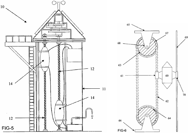 Fig.5 shows an embodiment where which a pair of buoys 14 are present. Each buoy is associated with its own shaft 12 and may move up and down inside vessel 11 independent of one another. In Fig.6, an alternative embodiment of the present invention is illustrated, where the buoy 60 has a connecting method 61 in the form of a cylindrical sleeve through which a guide chain 62 passes. Chain 62 is provided in an endless loop and is located on an upper tracking device 63 and a lower tracking device 64, both of which are pulleys. The upper pulley 63 may be fixed to an upper wall (not shown) of a vessel (not shown) via a bracket 65, while the lower pulley 64 may be fixed to a lower wall (not shown) of a vessel (not shown) via a bracket 66. The connection mechanism 61 contains ratchets which engage with the links of the chain 62 when buoy 60 moves downwards. Thus, as buoy 60 moves downwards, chain 62 also moves, thereby causing both the upper and lower pulleys to rotate in a clockwise direction. The upper and lower 64 pulleys have a series of indentations 67 corresponding to the shape of the links of the chain 62. In this way, the chain 62 sits in the indentations 67 and grips the tracking device (63, 64), thereby ensuring that the tracking device (63, 64) rotates. In the embodiment of the invention illustrated in Fig.6, a work shaft 68 is associated with the upper pulley 63 such that rotation of the upper pulley results in rotation of the work shaft 68. The work shaft 68 is located substantially perpendicular to the direction of travel of the buoy 60. The work shaft drives a generator to produce power. 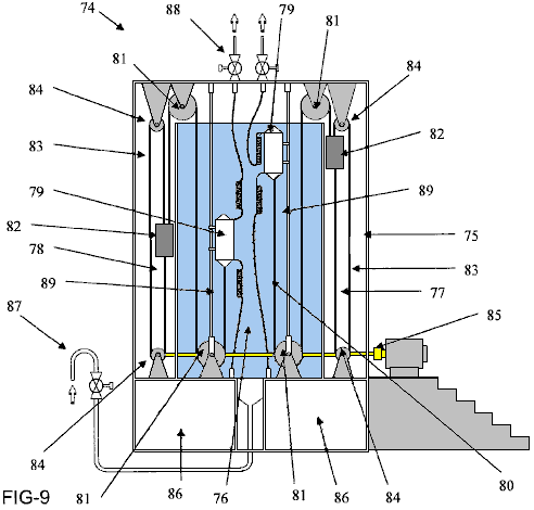 Fig.9 shows an alternative embodiment of this energy generation system 74. The system is comprised of a vessel 75 having a fluid-filled “wet” compartment 76 and one or more “dry” compartments (in this case, a pair of dry compartments 77, 78) with no liquid in them. These dry compartments may be fabricated from any suitable material, such as, concrete, steel, fibreglass, plastic or any combination of materials. The system also has a pair of buoys 79 each with a deflatable bladder-like construction. The buoys have guide rails 89 which ensure that the buoys move smoothly up and down inside the vessel 75. In this embodiment of the invention, air reservoirs 86 are located in the base of the vessel 75. Air enters the reservoirs 86 through inlet 87, while air exiting from the buoy 79 is vented through valves 88. The vented air may either be expelled to the atmosphere or recycled to the reservoirs 86. Each of the buoys is designed to be connected to one end of a chain or rope 80. A weight 82 is connected to the other end of the chain or rope 80. The chain or rope 80 has a series of pulleys 81 such that when the buoy is inflated and filled with air, the buoyancy is greater than the weight 82 and so the buoy rises in the vessel. When the buoy 79 is deflated, weight 82 is heavier than the buoyancy and so the buoy sinks in vessel 75. In the embodiment illustrated here, the weights 82 are located in the dry compartments 77,78. There are several reasons for this, including that, by locating the weights 82 in the dry compartments 77,78, the velocity of the weights 82 in the downward direction is increased, and therefore an increase in the energy produced by the system 74 is experienced. The weights 82 are associated with second ropes or chains 83, such that vertical movement of the weights 82 results in the rotation of the second ropes or chains 83 around a pair of sprockets 84. Rotational energy generated by the rotation of the second ropes or chains 83 is transferred to a power generation device 85 (such as a turbine or the like) in order to generate power (e.g. electrical power) In spite of its mechanical complexity, the Hidro design is offered as a commercial generator with tens of kilowatts of excess power, indicating that buoyancy is a significant method of generating power, based on the fact that water is hundreds of times heavier than air. Due to its weight, movement in water is slow but can be very powerful. The helical groove method of converting the vertical movement of the floats into rotational power is used because of this as it has a very high ratio between shaft turns and movement along the shaft. This can be understood when you consider the fact that a complete revolution of the shaft is caused by the float moving up just one step to the next thread position directly above. The turns ratio for the complete float movement is determined by the angle of the groove cut into the drive shaft. One other thing which needs to be considered for such a project is the weight of the overall structure when filled with water. The overall weight is liable to be many tons and so the footing underneath the generator needs to be very robust. Also, while compressed air is mentioned, giving the impression of cylinders of compressed air or gas, For continuous operation one would expect an air pump to be used. Whether or not an air pump is used, the diameter of the air hoses needs to be considered. Most people think that a gas can flow along a pipe or tube very easily. That is not the case. If you want to get a feel for the constriction caused by a pipe, then take a one metre length of 6 mm diameter plastic tube and try blowing through it. No significant amount of air will pass through the tube even if you blow very hard. The web site www.engineeringtoolbox.com shows this table:  Notice the major difference in carrying capacity of any of these pipes with just the change from a 10-foot (3 metre) length to a modest 20-foot (6 Metre) length, and those lengths are the sort of lengths needed for many applications. Also, look at the figures for, say, the 0.5 inch (nominal) diameter pipe. With just a 10-foot length, it would take a full two minutes to pump just one cubic foot of air through it. It follows then, that pipes of considerably larger diameter are needed for a project like the ‘Hidro’. It is possible to construct a much more simple version of the ‘Hidro’, perhaps like this: A Simple Buoyancy Power Generator 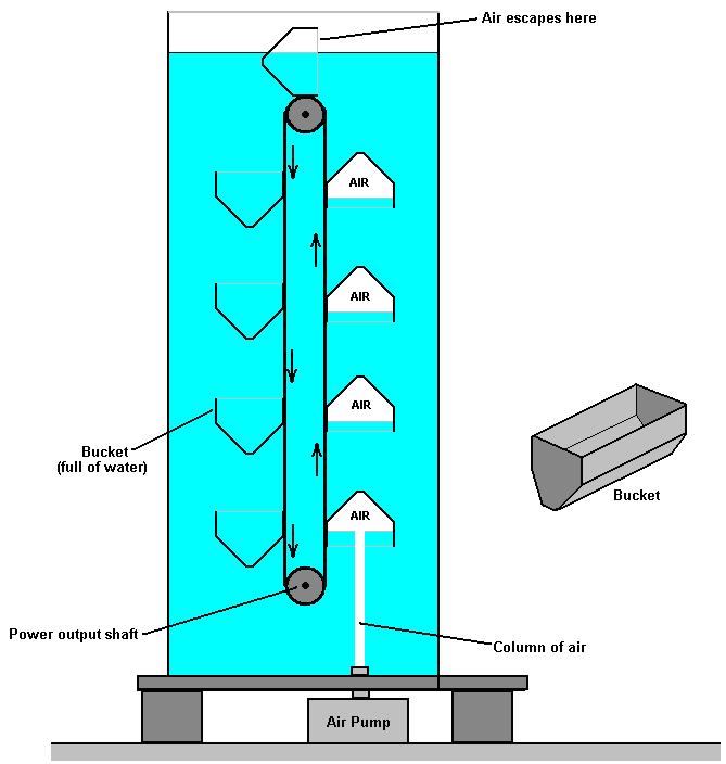 A simple hydraulic, buoyancy-powered generator can be constructed, with two or more horizontal, rotating shafts submerged in water in such a way that they are effectively positioned one above the other. Each shaft has one, and preferably two or more sprocket wheels mounted on it. Each of these sprocket wheels engages with a continuous chain loop which also engages with the sprocket wheel which is positioned vertically above it. These vertical chain loops form a belt-style support for a series of identical buckets. On one side of the vertical belt the buckets have their open face upwards and on the other side the bucket openings are facing downwards. An air pump is positioned directly underneath the set of buckets which have the bucket openings facing downwards. The air pump generates an upward-moving stream of air which collects in the rising buckets, displacing the water filling the bucket. This results in a powerful upward thrust caused by the buoyancy of that bucket, and the thrust causes the bucket to move upwards, rotating both horizontal shafts and bringing another water-filled bucket into position above the air pump. A gearing system transfers the rotation torque thus produced, to a generator which produces electricity for general purpose uses. This is a generator whose input shaft is rotated through buoyancy caused by air-filled containers submerged in a tank of water or some other suitable heavy liquid. Continuous, powerful rotation of the generator shaft is produced through the use of one or more conventional, commercially available air pumps. An air pump is used to fill a series of containers which are open at one end and which are attached to what is effectively a belt arrangement created by two strong chain-link loops which mesh with sprocket wheels mounted on two shafts, either, or both of which can be utilised for the extraction of useful power, preferably for driving an electricity generator but not necessarily limited to that function as any powerful torque has many useful applications. Objectives are to provide a power generation system which is very simple in form and which can be understood, operated and maintained by people with minimal training. Also, a system which uses components which are already readily available, thus avoiding significant manufacturing costs, and one which operates without the need for any kind of complex mechanism or high-precision equipment and which can operate with a wide range of commercially available products. Fig.1, is a simplified partial schematic cross-sectional view showing the main components of the generator as seen from one end 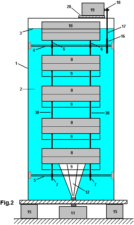 Fig.2, is a cross-sectional conceptual schematic view showing the front view of the generator in its most simple form. 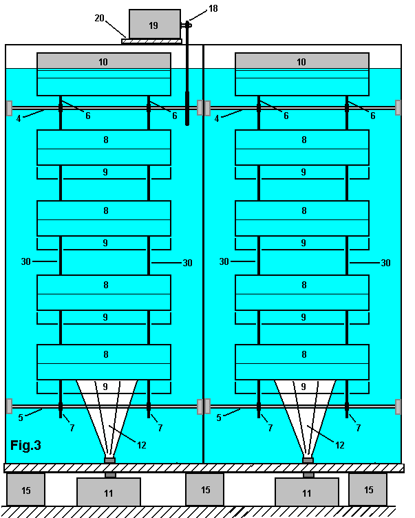 Fig.3, is a cross-sectional conceptual schematic view showing the front view of the generator where more than one set of buckets is used 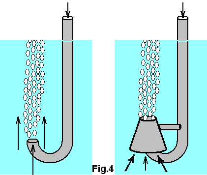 Fig.4, is a perspective conceptual view showing arrangements for a simplified air-feed system which operates from above the tank. Fig.1, illustrates the overall concept of the generator in its most simple form where lightweight rigid buckets are used to capture the rising air from the air pump. In this Figure, a water tank 1, holds water or other suitable liquid 2. The surface of the liquid 3, is indicated to illustrate the fact that a bucket 10, which is in the process of turning over at the top of its orbital motion, is positioned so that one edge of the bucket is above the surface of the water, which allows the air which was trapped inside the bucket to escape into the atmosphere and the water fill the entire bucket causing only a very minor turbulence when doing so. This is a desirable, but not essential feature as the air trapped in any bucket will escape upwards as soon as the bucket starts its downward movement, positioning its open end upwards, although this causes unnecessary turbulence inside the tank. One possible bucket shape is shown in perspective view, but many different bucket shapes may be used, including flexible membrane types or alternatively, hinged-plate types which have very much reduced resistance to moving through the water when in their collapsed state during their downward movement. The buckets 8, 9 and 10, are attached to two strong chains 30, which mesh with the upper sprocket wheel 6, mounted on the upper axle 4, and the lower sprocket wheel 7, which is mounted on the lower axle 5. Although it is not visible in Fig.1, there are two upper sprocket wheels 6, two lower sprocket wheels 7, and two chain loops 30, although these can be seen in Fig.2. The tank is supported on a robust plate 14, which itself is supported by a series of pillars 15 which rest on a secure footing 16, providing operating space underneath the tank for the installation and maintenance of the air pumping equipment. As fresh water weighs 1000 Kg per cubic metre, the weight of the operational generator system is substantial and so this must be allowed for when assessing the footing needed to support the tank and it’s contents. While a thin-wall tank is shown in Fig.1, many different forms of tank may be utilised, including earth bank and plastic membrane styles, or resurfaced abandoned well shafts. The tank of Fig.1 presumes that the lower axle 5 is taken out through the wall of tank 1, using an arrangement similar to that used for the drive shafts which power the screws of ships and other power vessels. While an arrangement of that type provides a drive shaft which is conveniently close to the ground, the much more simple arrangement shown in Fig.2 where the output power is taken off using the very simple chain and sprocket wheel method utilised for the bucket supports (chain 30, and sprocket wheels 6 and 7). In general, the more simple and straightforward any design is, the better it works in practice and the lower any maintenance costs become. Referring again to Fig.1, when activated, air pump 11 produces a stream of air 12, which flows rapidly upwards. This stream of air 12, once established, does not have to push against the head of water as immediately above the nozzle of the pump is a rapidly rising column of air, sustained both by the exit velocity from pump 11 and the natural upward movement caused by the relative weights of water and air (as water is several hundred times heavier than air). This column of air would normally flow straight upwards in calm water, but should it be found that turbulence in the water tends to push the rising air away from its vertical path, baffles can be placed around the pump and positioned so that the air stream is forced to stay within the same section of water taken up by the rising buckets. The rising air enters the lowest of the rising buckets and collects in it, forcing the water out of the open bottom of the bucket. If the rising bucket is not completely filled with air before the next bucket moves between it and the air pump, the trapped air will expand as the bucket rises and the water pressure reduces due to the lesser depth. Any one bucket with a substantial amount of air in it will create a very significant upward force due to buoyancy, air being about one thousand times lighter than water. Each bucket on the rising side adds to that upward force and consequently, the chains 30 need considerable strength. The weight of the buckets on each side of the chain match and so the main advantage of light buckets is to lower the inertial mass of the moving parts. Movement through the water is relatively slow but this is offset by gearing between the output drive shaft and the generator’s input shaft. The power of the system can be increased by adding more buckets in the vertical chain, increasing the water depth accordingly. Other ways of increasing the power include increasing the volume inside each bucket and/or increasing the flow rate produced by the air pump or pumps used. Another simple method is shown in Fig.3 and discussed below. An alternative to air pumps is to use tanks of a compressed, non-polluting gas, possibly air. The buckets shown in the various figures are rigid, very simple shapes, possibly made by a plastic moulding process in order to be cheap, strong, lightweight and permanently water-resistant. There are, of course, many possible variations on this including using rigid hinged plates sealed with a strong flexible membrane, allowing the buckets to fold and become streamlined on their downward path, and opening as soon as they turn to start their upward movement. There are many mechanisms which can provide this movement, but it is a matter of opinion as to whether or not the extreme simplicity of rigid buckets is worth sacrificing Fig.2 shows a schematic layout of the generator when seen from the side. The same numbers apply to the components already seen in Fig.1. The arrangement seen in Fig.2 is the most simple, basic, single bucket set. The near-side rising buckets 8 obscure the view of the far-side falling buckets 9 and only the lowest part of the falling buckets 9 can be seen in this view. Fig.1 shows buckets which are some two and a half times longer than they are wide, but this, of course, is just one option among literally thousands of possible proportions. The size and shape of buckets is related to the performance and number of air pumps being used for any one set of buckets and that choice depends on what is available locally at a reasonable price. It would not be unusual for two or three air pumps to be used side by side along the length of the bucket 8 although Fig.2 only shows a single pump. Fig.2 also shows a simple method for power take off where a large diameter sprocket wheel 16 is mounted on the upper axle 4, and driving a much smaller diameter sprocket wheel 18 which is mounted on the drive shaft of the electricity generator 19 which is mounted on plate 20 which is attached securely to the top of tank 1. Fig.3 shows one of the possible arrangements for increasing the system power without increasing the depth of water used. Here, the axles 4 and 5 extend far enough to allow another set of buckets to drive them, increasing the torque very substantially. While Fig.3 shows one extra set of buckets, there is, of course, no reason why there should not be three or more sets of buckets side by side. It should be noted however, that the partitions shown between the bucket sets are not there just to reduce the water swirling but are needed to support the bearings which are essential for the extended axles, since without those, the diameter of the bars used for the axles would have to increase very markedly to avoid unwanted flexing along their length. While the second set of buckets has been shown aligned exactly with the first set, there is an advantage in offsetting them relative to each other so that the output torque is more even with buckets emptying and filling at different points in the bucket cycle. Fig.4. shows a method for further simplification, where the air is pumped from above the water surface. It is a matter of concern to most people, that the pressure of the head of water above the air pump is a major obstacle to overcome and will be a continuous opposing force during operation of the generator. If air is being injected from underneath the tank, then initially, that pressure head has to be overcome. However, once the air flow is established, a vertical cigar-shaped area of water vortex is established by the rising air stream. This three-dimensional annular vortex negates the water head in the small area immediately above the air nozzle, and almost sucks the air out of the pump, after the initial introduction of the air has been accomplished. There is another way of achieving this desirable effect without ever having to pump against the total head of water, and that is to use a mobile air pipe as shown in Fig.4. Initially, the air pump is started and lowered a short distance into the water. The opposing head of water is not large and the water vortex can be established quite easily. The pipe is then lowered very slowly, so as to maintain the vortex at a progressively lower depth, where, in spite of the increased head of water, the pump does not have to overcome that head. When the pipe outlet reaches the operational depth, it is then rotated to bring it under the set of rising buckets. The major advantage of this arrangement is that the tank is as simple as possible, with no possibility of leaking, and so abandoned wells can be modified to become energy generators. Alternatively, an earth bank can be erected to form an above-ground tank, possibly sealed with a plastic membrane. This method also avoids needing to support the weight of tank and water above a work-area where the air pump or compressed-air cylinders are located and maintained. The creation of the water vortex can be assisted by the addition of a cowl around the pipe exit as shown in this figure, but that is an optional feature. The Ribero Buoyancy Patent. While internal combustion engine demonstrate that considerable power can be had from motion which moves backwards and forwards continuously, that sort of action is not very efficient as there is continuous reversal of the oscillating drive components. The floats in the (very successful) ‘Hidro’ design shown above. A different design is shown in the 2011 patent of Renato Bastos Ribero of Brazil. Here is an excerpt from that patent: Apparatus and associated methods to generate useable energy 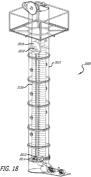 Abstract: The present disclosure relates to an apparatus and associated methods for generating energy by capturing and taking benefit of the energy generated by any quantity of air surfacing inside water. In exemplary embodiments, the apparatus comprises compressing a lower density gas in a liquid medium, allowing the gas to naturally rise to the surface of the liquid medium and then capturing the energy generated by the surfacing gas.  Fig.2 is a perspective upper view of a rotor disc for compressing a gas into a liquid medium. This disclosure is in two stages which, in this case, work together. The first stage consists of the creation of energy with the introduction of air at the bottom part of a water column. Once introduced, the air creates energy when moving towards the surface. The introduction of air into the water is the main point of this first part of the disclosure. A method was created in order to use a very small quantity of energy when doing this. The teeth on the disc, when rotated in water, water to flow away from the area between the teeth, lowering the pressure there and allowing the easy introduction of air in that area. Without air introduction, water would not move away and the pressure would not be reduced. The purpose of the cone is to spread the incoming air. The second section of the present disclosure refers to a system with the objective of capturing the air which is inserted at the bottom of a water column or tank, while moving towards the water surface  As shown in Fig.16, buckets 2030 descend on a continuous chain 2020 which passes around a lower and an upper wheel or pulley. On reaching the lower pulley, the buckets turn around the bottom pulley 2014 and line up again on the ascending side of the chain. Immediately after turning around the bottom pulley, each bucket receives the rising airflow  Fig.17 shows the arrangement at the top of the water tank 2010. Buckets 2030 rising due to being filled with air, turn over as they pass around the top pulley 2018, releasing the air inside them and start descending again towards the bottom pulley. The upper axle 2018 has an estimated rotational speed of 120 rpm. In Fig.17 I (Ribero) am showing the transmission of this energy to an axle at the top of the water column where we have a generator 2050 requiring a rotation of 300 rpm plus an engine connected to another generator with rotation of 600 rpm. This part of Fig.17 is only illustrative to show that we shall generate energy at the primary axle at 120 rpm, or use any kind of transmission to more convenient rotational speeds. I think that the words marked in red indicate that although this patent has been granted, the generator has never been built and is only an idea. Personally, I am highly dubious about the mechanisms which are supposed to give reduced water pressure at the air intake, as I don’t think that they would work, or if they do, certainly not for the reasons stated. What he wants to do can certainly be done, but not in the way that he suggests. If the axles are rotating at the 120 rpm which he suggests, then that would allow less than one eighth of a second to fill each bucket and while the notion of reduced water turbulence through the buckets touching each other, I don’t think that the method described is feasible. So, while we can be sure that buoyancy methods are perfectly capable of generating serious power, we need a better design than either of the two shown here as the Hidro appears to be very expensive to build The Thirty Kilowatt Motor The recent website shows a gravity-powered motor which is capable of driving a 30-kilowatt electrical generator. This is certainly not a home-build project and the cost of construction and day-to-day maintenance cost makes this appear to be a very uneconomic project. However, one enormous advantage of the building of these two generators is that they show very clearly that free-energy is available and perfectly viable. The people building these two constructions point out very clearly that these are graivty-powered motors rather than just electrical generators. While these motors can drive electrical generators, it is emphasised that they can also perform any task which needs a motor, such as pumping, drilling, etc. The size of these motors is substantial as can be seen from the following pictures: 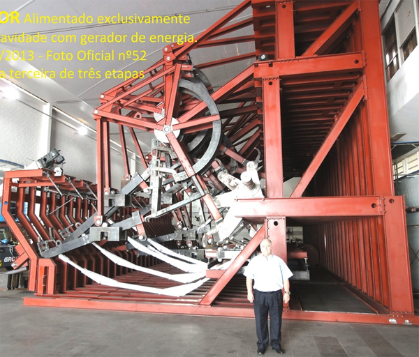 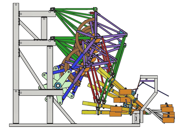 The Torque Generator of William F. Skinner In 1939, William Skinner of Miami in Florida, demonstrated his fifth generation generator powered by spinning weights. His demonstration can still be seen here where he shows his design powering a twelve-foot lathe, a drill press and a power hacksaw, all simultaneously. The newsreel commentator states that the output power was “1200% of the input power” which is COP=12 but it is highly likely that he should have said “1200 times” rather than “1200%” because he continues to state that using the design would allow a one-horsepower (746 watts) input power to power 3,500 homes. If it were COP=12 then each of those 3,500 homes would receive less than 2.6 watts, which is clearly wrong. At the much more likely COP=1200, each household would receive on average, 255 watts, which might be just possible in 1939 when few appliances were electric. Anyway, Skinner’s impressive equipment could be driven by a single cotton thread drive band while powering his whole workshop. It looked like this: 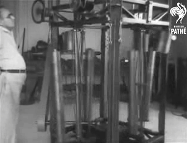 This design has four nearly vertical shafts, each braced to give additional rigidity. These rotating shafts pass their rotating power to the mechanical output drive belt seen on the left. Each of these rotating shafts has a heavy weight in the form of a thick, short cylinder mounted high up near the top of the shaft and what is probably an even heavier weight in the form of a long narrower cylinder attached near the bottom of the shaft as seen just to the right of the output drive belt. These four identical sets of shafts with their pairs of weights spin two or three times per second and produce the whole of the output power. As far as I am aware, Skinner never patented his design or disclosed how it worked. However, the operating principle is very simple indeed although it may take you a while to grasp how it works. You can check this out quite easily for yourself if you have access to an old-fashioned chair with four rigid legs like this:  Tilt the chair over so that it is balanced on one leg. You will notice that almost no effort is involved in keeping it in that position as all of the weight is supported by the floor through just one of the legs. Now, move the top of the chair by a very small amount and keep the top of the chair in that position. You will notice two things: first, very little effort was needed to move the top of the chair and second, the chair now swings around and becomes stationary on the same side that the top of the chair was moved. Notice two other things: the chair swung around because of your moving the top slightly and you did not swing it around, and if the chair is heavy, the amount of energy in the swinging chair is very much greater that the amount of energy which you applied to the top of the chair. If you were to keep moving the top of the chair in a tiny circle, then the chair will spin around continuously for however long that you choose to wobble the top of the chair. The amount of energy in the spinning chair is very much greater than the energy which you are expending to make the chair spin. So from where is that extra energy coming? What is happening is that the chair swings round under gravity to reach the lowest possible point for it with the new position of the top of the chair. But, before it can get there, you move the top of the chair further around and so the chair has to swing further in order the reach the lowest point. But before it can get there, you move the top again ….. The chair keeps swinging round and round, pulled by gravity, for as long as you choose to keep moving the top. But, no matter how heavy the chair, very little effort is needed from you to cause the spinning. Skinner had a mechanism at the top of each vertical drive shaft, and that mechanism kept moving the top of the shaft in a small circle while allowing the shaft to rotate freely at all times. That caused the very heavy weights attached to the shaft to keep spinning around, and he used that power of the heavy spinning weights to power his whole workshop. Moving the top of the shafts required so little power that he used a 93-watt electric motor and to show that he was not even using all the power of that small motor, he used a single cotton thread as a drive band to move the tops of the four power output shafts. His mechanism looks complicated. This is partly due to the fact that there are four identical power shafts with their weights, mounted in the one compact frame and that makes the device look more complicated than it really is. It is also due to the fact that the system shown in the newsreel is William’s fifth version of the device. It is likely that his earlier, much more simple versions worked well and encouraged him to build even fancier versions. There are two forums where members of those forums are trying to work out exactly how his final version machine worked and then replicate the design for current day use as it is a neat system for accessing additional usable power. Those forums are at: www.overunity.com and www.energeticforum.com It needs to be remembered however, that it is not actually necessary to replicate William’s fifth version, but instead it would be quite enough to use the principle of the spinning chair to produce a simple mechanism where the input power is far less than the output power. If we consider what is happening, then perhaps we can understand Skinner’s complicated-looking arrangement. We can consider just one of the four axle shafts The large weight is spinning around in a circle and that motion is then used to power the output shaft. In order to reduce the effort needed to spin the weight, the axle shaft has been made thinner and four bracing rods have been used to brace the shaft in exactly the same way that sailing yacht masts are usually braced with “spreaders” to hold the bracing out from the mast and so give greater overall stiffness. So we can ignore those bracing bars as they have nothing to do with the actual operation of his design, but are merely his choice out of many different construction options. Remember the spinning chair and consider what has to be done to spin Skinner’s heavy weight. The top of the shaft has to be moved in a small circle. Looking down from the top the situation is like this: 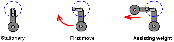 When the system is switched off, the weight attached to the bottom of the shaft comes to rest directly underneath the top of the shaft. When the system is started again, the first move is to shift the top of the axle shaft ninety degrees around. This is the start of the rotary movement and initially, the movement is slow as it takes the heavy weight some time to get moving. To reduce the effort of moving the top of the shaft ninety degrees ahead of the big lower weight, Skinner has added a weight at the top to assist the movement in that direction. 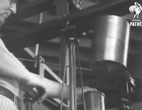 Skinner also took advantage of his very large workshop to use a belt-driven mechanism above the top of the shaft, in order to reduce the effort of moving the top of the axle shaft even further (to the level where it could be driven by a cotton thread). He used four separate identical shafts in his construction for two reasons: first, the overall output power is increased and second, any sideways forces stressing the mounting frame are matched on every side, which is helpful when you have heavy weights on a rotating arm as Skinner did. As the output shafts appear to be rotating at about 150 rpm, Skinner opted to use a straight mechanical drive. Back in 1939, electrically-driven equipment was not as widespread as it is today, but nowadays we would probably prefer to have an electrical output rather than a mechanical drive although that mechanical drive could be used for driving pumps and other low-speed devices. So, we are faced with introducing some form of gearing which can raise that 150 rpm to the much higher level preferred by most alternators. While it would be possible to use an ordinary 12-volt motor as a generator and produce a 12-volt electrical output, it is likely to be more convenient to use an off-the-shelf electrical generator, perhaps a very low-friction one like this which has been designed for wind-power operation and which has a 12V or 24V 3-phase output:  The fact that the output is 3-phase can sound a little daunting, but the conversion to DC is quite straightforward:  The output can be converted to DC with six ordinary diodes or a integrated diode arrangement can be used where there is a connecting tag for each of the three outputs and a separate tag for the DC Plus and for the DC Minus. The currents involved are quite high as 400 watts at 12-volts represents more than 33 amps and the peak output of 500 watts is a current of about 42 amps. For that reason, the 3-phase rectifier blocks are rated at 50 amps which sounds very high until you do the calculations and discover what the current is likely to be. It should also be borne in mind that the DC output wire has to carry that level of current on a continuous basis and so fairly robust wire is needed. If the voltage were 220V then the wire would be carrying more than 9 kilowatts at that current flow, and so the normal 13-amp mains wire is just not sufficient and instead, we need to use thick wire or more than one strand of wire for both the Plus and the Minus connections. This particular generator is not expensive and can output 400 watts of electricity (33 amps) continuously. As the Skinner type appears to be spinning at 150 Hz, a gearing up of the output speed would allow greater output, so perhaps for a home-builder, the physical arrangement might be like this: 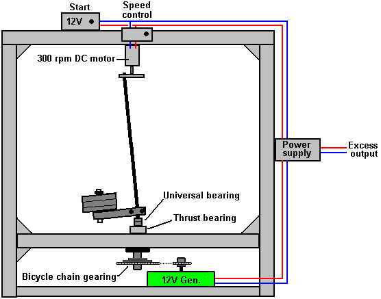 There are, of course, many different forms of construction which might be used, but with each of them, the question is, “how do you make the angled shaft rotate powerfully?”. If you can work out the complexities of Skinner’s fifth version shown in the newsreel, then that would certainly do the job. However, we would prefer a much more simple design and so we do not necessarily have to copy what Skinner did but instead we can just apply the principle which he demonstrated. One possible arrangement might be to imitate the chair experiment using a strong shaft with a weight attached to one side of it, perhaps like this: 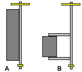 Version “A” uses the weight to stiffen the shaft but doing that raises the centre of gravity of the combined shaft and weight which may not be convenient. Version “B” increases the torque for any given weight by moving the centre of gravity of the weight away from the centreline of the shaft by means of extension arms. As the shaft rotates at a constant rate, the load on the shaft will be essentially constant and there should not be any significant flexing of the shaft although it might bend and remain with that same bend during all of the time when it is spinning if the weight is very high relative to the stiffness of the shaft. We do have to input some power to rotate the top of the drive shaft, but if we arrange things in any one of the hundreds of viable configurations, then the output power will be massively greater than our input power. An alternative arrangement which allows speed control (and so, output power control) is to take some of the generated output of electricity and use that to power an electrical drive which positions the top of the drive shaft. There will be many different ways of achieving that movement. One method for doing this might be: 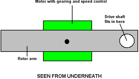 Here, the small electric motor shown in green is geared down and used to move the top of the drive shaft at whatever rate of revolution that we consider to be satisfactory, using a standard DC motor speed controller. It should be noted that no matter what angle is chosen for the axle shaft, that is always a constant relative to the motor arm moving it round in the circle at the top of the shaft. This means that no roller bearing is needed as there is no relative movement and the shaft will automatically take up that fixed angle. The drive motor arm moving the top of the shaft will probably not be long, as Skinner appeared to be moving the top of his shafts by about 40 mm away from the centreline of the bottom pivot, making only one degree or so for the angle of the shaft on every side of the vertical. It is, of course, not essential to convert the output power to electricity and instead it could be used in the same way that Skinner did, driving mechanical equipment such as water pumps for irrigation or extracting water from wells, milling operations for processing grain or for operating any form of workshop equipment. It is also not necessary to build the device anywhere near as large as Skinner did, and small versions could be used to power lighting systems, operate fans or cooling systems or for any other minor household requirements. The power output from the machine can be increased by increasing the weight attached to the output shaft, or by increasing the length of the arm holding the weight, or by tilting the output shaft through a greater angle (which increases the input power needed, but probably not by much), or perhaps by scaling the whole thing up so that it is physically bigger. Skinner’s design uses stiffening bracing on the output shaft, which suggests that the lighter the shaft is, the better the performance. Because of this, a prototype build might use a timber shaft of perhaps, 33 mm square as that is both light and very strong and rigid and it is a good shape for ensuring that there is no slipping of the arm which supports the weights. The top of the shaft is reduced slightly so that it has a circular cross-section. A 300 rpm motor rotates at a maximum of 5 turns per second and so is suitable for rotating the axle shaft. A suitable, low-cost motor of that type, looks like this: 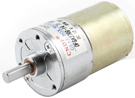 The motor needs to be linked to the shaft in a simple way which ensures that there will be no shaft slippage: 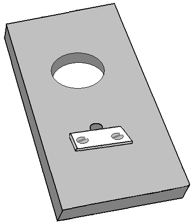 Perhaps cutting a suitable sized hole through a strip of material and using a strip of metal pressed into the flat face of the motor drive shaft (in addition to the hole being a tight push fit) would be adequate for this. A screwed collar or layer of epoxy resin holds the plate firmly to the motor as the plate is positioned below the motor and so gravity tends to pull the plate off the motor shaft at all times. It would initially be assumed that a ball bearing or roller bearing would be needed in this motor arm, but that is not the case as the axle shaft does not rotate relative to the motor arm and while the axle shaft can be a loose fit in the hole, there is certainly no need for a bearing. A commercial DC Motor Speed Controller can be used to bring the shaft rotation speed gradually up from a stationary start to the chosen rate of revolution: 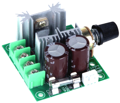 Using a commercial module like this means that no electronics knowledge is needed to build a working generator of this type. There are many options for providing the necessary weight which drives the generator. One possibility is to use a barbell shaft with as many weights as are required, that being a very simple alteration:  One of the hand grips can be cut and used directly as part of the mounting, perhaps like this: 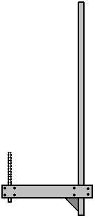 This simple arrangement allows the weight discs to be added and secured in any combination desired. As dumbbells are supplied in pairs, there are four discs of each side which allows a wide range of weight options going up in jumps of just 1 Kg which is very convenient. If the axle shaft has a square cross section, there is no tendency for the lever arm to slide around the shaft The following sketches are not to scale, but one form of construction might be: 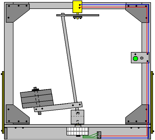 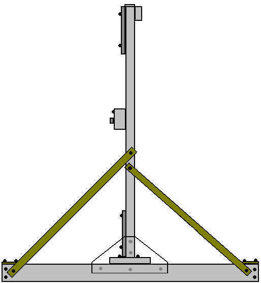 For this style of construction, four pieces of, perhaps, 70 x 18 mm Planed Square Edge timber are cut to perhaps 1050 mm and two 33 x 33 x 65 mm pieces epoxied and screwed to two of the pieces, 18 mm in from the ends:  Then the four pieces are screwed together while resting on a flat surface:  Then corner bracing triangles of MDF are screwed in place:  Then a 130 x 25 mm thick plank is attached across the width at the centre point and screwed in place:  Next, two lengths of the 18 mm thick timbers about 180 mm long are epoxied and screwed to the centre of the 25 mm thick plank, leaving 70 mm clearance to the end of the plank: 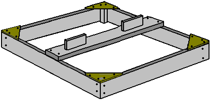 Two timber strips 1350 mm long, are cut and erected vertically, being attached by screws coming upwards through the 25 mm thick plank, and by MDF bracing triangles on one side and across the lower end of the verticals. If a spirit level is used to ensure that the vertical timber is actually vertical, then first, the four corners of the floor frame need to be weighted down to overcome any twisting and the floor frame confirmed to be actually horizontal before attaching the vertical timbers: 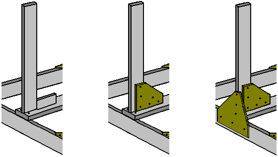 Each vertical needs to be braced on both sides with diagonal strip, either metal or timber: 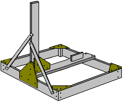 An 18 mm thick timber strip is screwed to the tops of the verticals. This deliberately positions the timber 18 mm off centre as the motor which rotates the top of the axle shaft has to be attached to the middle of this newest timber and that places the motor shaft very close to the central point of the base:  One slight disadvantage is that a packing piece is needed for the triangular MDF bracing pieces which increase the frame rigidity at the top:  At this stage, the construction will look like this: 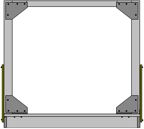 At this point, the 300 rpm motor with it’s actuator arm and the speed-control box can be fitted. The motor is located centrally, and the control box can be positioned anywhere convenient. The control box is merely a 12-volt battery pack of 1.2V NiMh AA-size batteries connected through a push-to-make press button switch and the commercial DC Motor Speed Controller, to the 300 rpm motor. With this arrangement, the motor can be powered up by pressing the button and adjusting the speed slowly up from stationary, getting the rotor weight moving gradually faster and faster until its best operating speed is reached. When everything is in place, then the rectified output of the alternator is fed into the control box, so that the Start button can be released and the device becomes self-powered from part of the output power. The initial step looks like this: 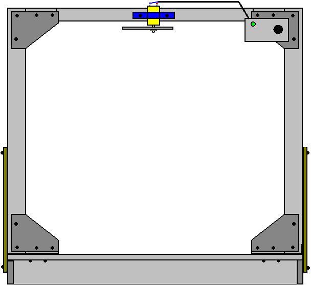 It should be explained that, with the exception of the 25 mm thick plank, all of this construction is only loaded very lightly as rotating the top of the axle shaft does not take much power or effort at all. Almost all of the rotating weight is located at the bottom of the axle shaft and that weight rests on some form of bearing which rests in the middle of the 25 mm plank. For a small version of the generator, such as this one, the rotating weight does not need to be all that great and so, the forces generated by the weight and its rotation about the bearing need not be a major thing. However, in spite of the fact that we are only dealing with limited forces which can be handled by simple components, people may be inclined to use a thrust bearing instead of allowing the weight to rest on the shaft of the alternator. A bearing of that kind may look like this:  Here, the base and inner ring do not move while the top outer ring revolves freely and can support a major load while it rotates. If we choose to use one of these, then an arrangement like this could be used: 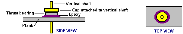 This combination has a cap (shown in yellow) with a central vertical shaft (yellow) attached to it, tightly encasing the upper ring of the bearing whose lower ring is securely attached to the 25 mm thick plank (grey) perhaps using epoxy resin (purple). This allows free rotation of the upper ring and vertical shaft while carrying significant loading. The power take-off in the arrangement shown is from the shaft projecting beneath the plank. Generally speaking, the electrical power output increases with increased speed of rotation, so gearing the alternator up so that it rotates much faster than the axle shaft is desirable and this arrangement may be convenient for that. If it is important to have the power take-off above the plank, then a strong bracket can be used to raise the bearing high enough above the plank to accomplish that. There are two separate forces acting on the bearing. One is always downwards as the bearing supports the rotating weight: 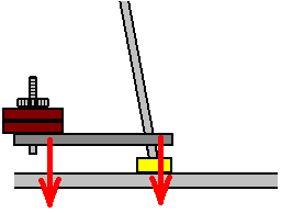 Then there is the sideways forces caused by the rotation of the (unbalanced) weight: 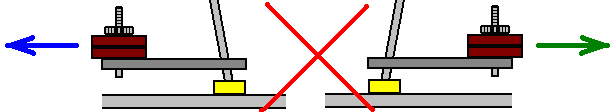 This sideways force is normally considered to be a major problem, however, in this instance, the weight is not being whirled around and trying to escape from the shaft in a horizontal direction, but instead, the weight is turning under gravity powered by its own weight, and the forces generated are quite different and in a different direction. Also, the rate of rotation is very small compared to the speeds which we automatically think about when considering an orbiting weight, typically, this rotation only being between 150 and 300 rpm. As far as the loading on the axle drive motor is concerned, the situation is like this: 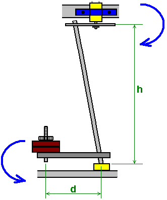 This is the position when at rest. The pull on the motor shaft at the top of the axle shaft is W x d / h where W is the weight at the end of arm d. The situation changes immediately the top of the axle shaft is rotated and the weight W starts to swing under the influence of gravity. I am told that the axle shaft needs to be light. With small weights, a rigid wooden shaft is adequate and it does not flex under the loading. I am assured that the bottom of the axle shaft needs a universal joint and a major version of this generator where the weights are very high, that is certainly true as the shaft will flex if designed to its minimum specification, but under these much less stressed conditions, there will be no flexing of the shaft when it is pulled sideways and as the shaft angle is a constant, I do not believe that any such joint is necessary. However, many people will wish to include one. These bearings come in different forms, and one of them looks like this:  It must be remembered that if a joint like this is fitted, then it will not be in constant motion, that is, the joints will take up one particular position and will maintain that position during the whole of the time that the generator is in operation. A compromise would be to provide a hinged movement in one plane by pivoting the axle shaft joint just above the thrust bearing: 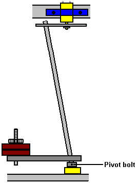 The electrical connections are quite straightforward:  The 12-volt battery pack of 1.2V AA-size batteries is connected to the motor speed controller when the button of the press-button switch is held down. This powers the motor, and as the axle shaft speeds up progressively, the generator starts producing power which is always fed to the speed controller box. As soon as the generator gets up to speed the press button switch can be released and the system runs on power produced by the generator. Excess power will be drawn from the generator output, but those links are not shown in the diagram. Patrick Kelly www.free-energy-info.com www.free-energy-info.co.uk www.free-energy-info.tuks.nl www.free-energy-devices.com |