|
Note: If you are not at all familiar with basic electronics, you might find it easier to understand this chapter if you read chapter 12 first.
The pulsed devices mentioned so far have had moving parts but rotating or fluctuating magnetic fields can be created without moving parts. An example of this is Graham Gunderson’s solid-state electric generator shown in US Patent Application 2006/0163971 A1 of 27th July 2006 which is shown on page A-1038 of the appendix. Another example is: Charles Flynn's Magnetic Frame Another device of this type comes from Charles Flynn. The technique of applying magnetic variations to the magnetic flux produced by a permanent magnet is covered in detail in the patents of Charles Flynn which are included in the Appendix. In his patent he shows techniques for producing linear motion, reciprocal motion, circular motion and power conversion, and he gives a considerable amount of description and explanation on each, his main patent containing a hundred illustrations. Taking one application at random: He states that a substantial enhancement of magnetic flux can be obtained from the use of an arrangement like this:  Here, a laminated soft iron frame has a powerful permanent magnet positioned in it’s centre and six coils are wound in the positions shown. The magnetic flux from the permanent magnet flows around both sides of the frame.  The full patent details of this system from Charles Flynn are in the Appendix, starting at page A - 338. Lawrence Tseung Lawrence has recently produced a subtle design using very similar principles. He takes a magnetic frame of similar style and inserts a permanent magnet in one of the arms of the frame. He then applies sharp DC pulses to a coils wound on one side of the frame and draws off energy from a coil wound on the other side of the frame. He shows three separate operating modes for the devices as follows:  Lawrence comments on three possible arrangements. The first on shown above is the standard commercial transformer arrangement where there is a frame made from insulated iron shims in order to cut down the "eddy" currents which otherwise would circulate around inside the frame at right angles to the useful magnetic pulsing which links the two coils on the opposite sides of the frame. As is very widely known, this type of arrangement never has an output power greater than the input power. However, that arrangement can be varied in several different ways. Lawrence has chosen to remove a section of the frame and replace it with a permanent magnet as shown in the diagram below. This alters the situation very considerably as the permanent magnet causes a continuous circulation of magnetic flux around the frame before any alternating voltage is applied to the input coil. If the pulsing input power is applied in the wrong direction as shown here, where the input pulses generate magnetic flux which opposes the magnetic flux already flowing in the frame from the permanent magnet, then the output is actually lower than it would have been without the permanent magnet.  However, if the input coil is pulsed so that the current flowing in the coil produces a magnetic field which reinforces the magnetic field of the permanent magnet then it is possible for the output power to exceed the input power. The "Coefficient of Performance" or "COP" of the device is the amount of output power divided by the amount of input power which the user has to put in to make the device operate. In this instance the COP value can be greater than one:  There is a limitation to this as the amount of magnetic flux which any particular frame can carry is limited by the material from which it is made. Iron is the most common material for frames of this type and it has a very definite saturation point. If the permanent magnet is so strong that it causes saturation of the frame material before the input pulsing is applied, then there can't be any effect at all from positive DC pulsing as shown. This is just common sense but it makes it clear that the magnet chosen must not be too strong for the size of the frame, and why that should be. As an example of this, one of the people replicating Lawrence's design found that he did not get any power gain at all and so he asked Lawrence for advice. Lawrence advised him to omit the magnet and see what happened. He did this and immediately got the standard output, showing that both his input arrangement and his output measuring system both worked perfectly well. It then dawned on him that the stack of three magnets which he was using in the frame were just too strong, so he reduced the stack to just two magnets and immediately got a performance of COP = 1.5 (50% more power output than the input power). The Transformers of Thane Heins. Thane has developed, tested and applied for a patent for a transformer arrangement where the output power of his prototype can be thirty times greater than the input power. He achieves this by using a figure-of-eight double toroid transformer core. His Canadian patent CA2594905 is titled "Bi-Toroid Transformer" and dated 18th January 2009. The abstract says: The invention provides a means of increasing transformer efficiency above 100%. The transformer consists of a single primary coil and two secondary coils. Magnetic flow is a thousand times easier through iron than it is through air. Because of that fact transformers are generally constructed on a frame made of iron or a similarly magnetic material. The operation of a transformer is nothing like as simple as school teaching would suggest. However, leaving parametric excitation aside for the moment, let us consider the effects of magnetic flow. The way that off-the-shelf transformers work at the moment is like this:  When a pulse of input power is delivered to Coil 1 (called the "Primary winding"), it creates a magnetic wave which passes around the frame or "yoke" of the transformer, passing though Coil 2 (called the "Secondary winding") and back to Coil 1 again as shown by the blue arrows. This magnetic pulse generates an electrical output in Coil 2, which flows through the electrical load (lighting, heating, battery charging, video displays, or whatever) providing it with the power which it needs to operate. This is all well and good but the catch is that when the pulse in Coil 2 finishes, it also generates a magnetic pulse, and unfortunately, that magnetic pulse runs in the opposite direction, opposing the operation of Coil 1 and causing it to have to boost it's input power in order to overcome this magnetic flow in the opposite direction, shown here by the red arrows:  This is what makes current scientific "experts" say that the electrical efficiency of a transformer will always be less than 100%. This effect is caused by the magnetic path being symmetrical. Like the flow of electricity, magnetic flow passes along every possible path. If the magnetic path has low magnetic resistance (generally due to having a large cross-sectional area), then the magnetic flow through that path will be large. So, faced with several paths, magnetic flow will go along all of them in proportion to how good each path is for carrying magnetism. Thane Heins has made use of this fact by making a transformer like this:  This style of transformer has got quite complicated magnetic flows when it is operating, although the diagram above only shows some of the flow paths generated when the input coil “Coil 1” is pulsed. The really interesting result is seen when that input pulse cuts off and we expect return magnetic flow from coil 2 and coil 3. What happens is this:  Assume that coil 2 and coil 3 are identical. The reverse magnetic flux coming out of coil 2 immediately encounters a junction with one path being far easier to use than the other. As a result, the vast majority of that magnetic flow follows the broad path, and only a small percentage flows through the narrow path. The broad path flow meets and is opposed by an identical large flow coming from coil 3, and those flows effectively cancel each other out. This produces a major improvement over an ordinary transformer. But, the small flow reaching the entrance to Coil 1 encounters two identical paths, and only one of those paths goes to coil 1, so the flux divides with half going towards coil 3 and half going through coil 1. That halves the strength of the already small percentage of the original, unwanted reverse magnetic flow into coil 1. The other half runs into the reduced flow from coil 3 and those halves cancel each other out. The overall effect is a really major improvement in the performance of the transformer as a whole. In the patent document, Thane quotes a prototype test which had a primary coil winding with 2.5 ohms resistance, carrying 0.29 watts of power. The secondary coil 1 had a winding with 2.9 ohms resistance, receiving 0.18 watts of power. The Resistive load 1 was 180 ohms, receiving 11.25 watts of power. The secondary coil 2 had a winding with 2.5 ohms resistance, and received 0.06 watts of power. Resistive load 2 was 1 ohm, receiving 0.02 watts of power. Overall, the input power was 0.29 watts and the output power 11.51 watts, which is a COP of 39.6 and while the document does not mention it directly, the primary coil should be driven at it's resonant frequency. A variation of this arrangement is to attach an outer toroid to the existing bi-toroid arrangement, like this: 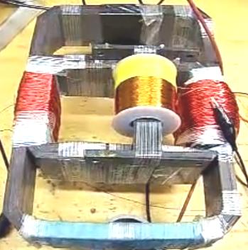 This prototype, as you can see, is fairly simple construction, and yet, given an input power of 106.9 milliwatts, it produces an output power of 403.3 milliwatts, which is 3.77 times greater. This is something which needs to be considered carefully. Conventional science say that "there is no such thing as a free meal" and with any transformer, you will get less electrical power out of it than you put into it. Well, this simple looking construction demonstrates that this is not the case, which shows that some of the dogmatic statements made by present day scientists are completely wrong. At YouTube Thane shows a video where he constructs his bi-toroidal transformer from three ordinary toroids held together with cable ties:  Thane then goes on to demonstrate the performance of this combination:  The LED associated with the power being fed to the primary winding is so low that no light is visible. The output LED is lit so powerfully that the camera has difficulty in displaying it. The dummy load is a single resistor placed across the third winding and there is a major performance difference when it is plugged into place. This video demonstrates very clearly, the difference caused by using a bi-toroidal transformer. This simple and elegant modification of the humble transformer, converts it into a free-energy device which boosts the power used to drive it and outputs much greater power. Congratulations are due to Thane for this technique and for his sharing it openly with anyone who is interested.   Professor Markov’s Transformers Professor Gennady Markov, General Director of STC "Virus" and author of many inventions and discoveries, received an international patent for a new a transformer design which he created. His work involves a new law in the field of physics and electrical engineering. He says: In 1831 Faraday discovered electromagnetic induction. Then his ideas were further developed by Maxwell. For more than 160 years following that, no one advanced fundamental electrodynamics by even a single step. Eight years ago, I applied for an international patent, valid in 20 countries, as I had created a transformer, which has already received four Russian patents. My discovery was made despite the "laws" of the great physicist Faraday who said that “magnetic fluxes in a magnetic circuit should be combined separately with the resulting combined flux moving in only one direction. Only then can you have a working transformer”. I dared to do the opposite: take a coil with two identical windings and operate them towards each other. This creates equal magnetic fluxes, moving toward each other, which cancel each other out, but do not destroy each other as Faraday and Maxwell claimed. I determined a new law: ‘The Principle of Superimposition of Magnetic Fields in Ferromagnetic Materials’. The superimposition - is the addition of magnetic fields. The essence of the law is that the magnetic fields are added, cancel each other, but they are not destroyed. And here the important part is "they are not destroyed" and that is the key fact on which my law is based. I wrote an article on this subject, which was published in the journal "Applied Physics". I demonstrated a transformer at an international exhibition in China, where it caused great interest among scientists and other experts. That transformer had excellent performance and in fact, it can raise or lower the voltage without any need for a secondary winding. My new law allows us, firstly, to create high-power transformers where the weight and size per unit of capacity is 20 to 30 times lower than in conventional Faraday transformers. Second, I created a transformer which, despite its large dimensions and power-handling capabilities, can operate at frequencies up to several megahertz (at the present time, a conventional transformer operates at frequencies of only 30 to 50 Hertz, and if you operate them at 100 Hz or higher, the metal overheats and the transformer breaks down). My transformer can operate safely at frequencies of millions of Hertz. Conventional transformers tend to be very bulky because they contain a great deal of iron with the weight of a standard 4 MW transformer being 3670 Kg. My 4 MW transformer weighs a total of 370 kg. When constructing a new transformer you can use any quality of steel quality and there are virtually no restrictions on the frequency range in which it can operate. Unlike conventional transformers, a new transformer can be transported from the place of manufacture to the point of use quite easily. This new transformer design gives us a huge opportunity to create a new generation of technology. Please note that the transformer does not operate at low frequencies. Its frequency range is 10 kHz to 40 MHz, and the voltage needs to be at least 40 volts. Here is most of Professor Markov’s patent EP 844,626: TRANSFORMER Abstract Several types of transformers are proposed which may be used as the main electrical engineering equipment of electric power stations, substations, power lines, in radio engineering, in devices for measuring, automatic control and regulation. At the heart of the invention lies the principle where the primary winding consists of two sections wound and connected to each other in such a way that during operation of the transformer, the magnetic flux created by one section of the primary winding compensates the magnetic flux created by the other section of the primary winding. The transformer comprises (Fig.2) a magnetic circuit, a primary winding consisting of two sections having an identical number of turns, wound in one direction on a core of the magnetic circuit. The windings of the two sections are connected to each other by their outputs, while the inputs of the windings serve as entrances for the power supply. The secondary winding is wound on the primary winding on the same core of the magnetic circuit, a load RH is connected to the secondary winding. The developed embodiments of the transformer are distinctive in that the sections of the primary winding are wound on one core of the magnetic circuit (3 embodiments) or on two cores of one magnetic circuit (4 embodiments), in that the direction in which the sections of the winding are wound is different (in one or opposing directions), and consequently there is a different connection of the windings, and are also distinguished by the presence of a secondary winding (in one embodiment there is no secondary winding). Description: Background Art Transformers are electromagnetic static converters of electrical energy which have two or more inductively coupled windings and are designed for the conversion of a sinusoidal alternating current of one voltage into an alternating current of another voltage with the same frequency. The principle of operation of a transformer is based on the effect of electromagnetic induction found by M. Faraday in 1831 (B.N. Sergeenko, V.M. Kiselev, N.A. Akimova. Electrical Machines. Transformers. Pub. "Vysshaya Shkola," Moscow, 1989). In accordance with specific features of construction and use, transformers can be divided into power, welding, measuring and special transformers. Power transformers, which are a necessary element of an industrial power network, have attained the most widespread use. Transformers have two basic parts: a magnetic circuit and windings. Furthermore, high-power transformers have a cooling system. The magnetic circuit is the structural base for mounting and fixing windings, taps and other elements of a transformer, and serve for amplification of the magnetic coupling between the windings. The part of the magnetic circuit upon which the windings are arranged, is called the ‘core’, the remaining part, closing the magnetic circuit, is called the ‘yoke’. The windings of a transformer serve to create a magnetic field by means of which electrical power is delivered. The winding of the transformer to which electrical power is applied is called the primary winding, while the winding from which power is taken is called the secondary winding. Known inventions are concerned with the creation of special transformers or with changes of particular structural elements of the transformer; realisation of magnetic circuits from certain materials and their structural appearance, connection of magnetic circuits to each other where there is a number of magnetic circuits n, use of different types of insulation and cooling systems, realisation of the windings, additional elements in order to enhance noise immunity. A transformer for vehicles is known [PCT (WO), 93/14508]. The small-size, light transformer, comprises a shell-type iron core on which inductively coupled input and output windings are wound. A magnetic element with an air gap is provided between the input and output windings, while a magnetic element creating strong magnetic coupling is located between the output windings. The element is disposed in a gap 5d surrounded by the core and consists of a magnetic circuit without gaps and an insulating plate holding the magnetic circuit and insulating it from the core and windings. A transformer is known [PCT (WO), 93/16479], in which the core is made from ferromagnetic wire. A spirally wound core from ferromagnetic wire is proposed. The core is used in a differential current sensor in a switch to open a circuit, which operates when there is a short circuit to ground. The ferromagnetic wire is wound in a spiral, the turns of which are parallel to each other and extend over the whole length of the core. The latter is positioned near current lines, with monitoring of a short circuit therein, wherein both lines are connected to a power source. The currents in them flow in opposite directions. The core interacts with a magnetic field created by those currents. Where a ferromagnetic wire is used, it is possible to increase substantially, the surface area of the core without increasing its cross section, and consequently, its size. A transformer is known [RU, C1, 2041514] consisting of one or several strip cores made from a magnetic alloy comprising silicon, boron, iron and several windings inductively coupled to the core, wherein the magnetic alloy additionally comprises copper and one or several components selected from the group consisting of niobium, tantalum, tungsten, molybdenum, chromium, and vanadium, with the following ratio of alloy components, atom percent: copper - 0.5-2.0; one or several components from the group consisting of niobium, tantalum, tungsten, molybdenum, chromium, vanadium - 2-5; silicon - 5-18; boron - 4-12; iron - balance. A transformer is known [PCT (WO), 93/18529] comprising 3 or 4 types of insulation units with one winding. Transformers of this type are easily assembled with small expenditure of time. A current transformer with strip insulation is known [RU, C1, 2046425] comprising a single-turn or multi-turn primary winding and secondary windings which are placed in a damping screen and have terminals. Wherein the windings are secured by means of insertion support and connecting bushings and are covered with epoxy compounds. The transformer is additionally provided with insulation bushings, a screen which is placed on the primary winding, and support clamps. Insulation bushings are mounted in semi-oval slots of the clamps, the damping screen is made open and consists of two parts, with an insulating pad mounted in the gap between the two parts, and the insertion support bushings are mounted on the insulating bushings in a manner adaptable for securing the damping screen. A high-voltage transformer is known (RU, C1, 2035776] comprising a porcelain housing mounted on a socket on which an active portion enclosed in the housing, is positioned on compressing posts. The active portion consists of a mixed rectangular magnetic circuit with yokes, upper and lower horizontal cores on which windings are positioned. In order to reduce the noise immunity the transformer is provided with additional screens - a middle one, upper and lower ones, and a capacitive screen. A winding for a high-voltage transformer is known [PCT (WO), 93/18528]. A connecting element is secured to the conductive portion of the winding to enhance its mechanical properties, and a second connecting element is connected to the aforesaid connecting element by means of insulating elements. Such, a winding can be used as a low-voltage winding with a small number of turns in dry transformers with a resin poured over them. A heavy-current transformer is known [RU, C1, 2027238] comprising a primary winding disposed on a toroidal core and a secondary winding encompassing the primary winding. Wherein the secondary winding is made by a bundle of flexible conductors placed in the inner cavity of the torus in N sections, and from the outer side of the torus in N-1 sections, where N is the number of turns of the secondary winding, wherein the bundle is arranged in one or more layers on the outer side of the torus. However, all the known transformers are built according to one principle, in, particular - supplying electrical power to the primary winding and taking electrical power from the secondary winding, and they all have these drawbacks: multi-turn secondary windings in step-up transformers, which nevertheless operate in a rather narrow frequency range (50-400 Hz); the limited frequency range of the transformers being related to losses in the magnetic circuit at higher frequencies; high resistance of the windings, i.e. the necessity that the no-load condition of the transformer be taken into account during calculations of the number of turns in the secondary winding to obtain a predetermined output voltage; the complexity of the construction of the transformers when all possible kinds of additional elements, insulation etc. are used to reduce the above drawbacks. Disclosure of the Invention At the base of the invention lies the object of creating such a transformer in which the possibility of winding the secondary winding with wire, including wire with a cross-section equal to the cross-section of the primary winding, is realised, and the reduction of the number of turns in the secondary winding of high-voltage transformers and expansion of the number of variants of existing transformers are attained. This object is achieved in that a construction of a transformer is proposed which comprises a magnetic circuit, at least two windings, inlets for a power supply, outlets for a load, wherein the primary winding consists of two sections with an identical number of turns, the sections being connected to each other in a series circuit. A transformer is proposed in which two sections of a primary winding are wound in one direction on one core of the magnetic circuit, the sections are connected in a series circuit by connection of the outputs of the windings, and the point of their connection serves as an outlet for the load, while the inputs of the windings of the sections serve as inlets for the power supply. The above technical result is achieved by creating a transformer, two sections of the primary winding of which are wound in one direction on one core of the magnetic circuit, the outputs of the windings of the sections are connected in a series circuit, while the inputs of the section windings serve as inlets for the power supply. The secondary winding is wound on the same core of the magnetic circuit, over the sections of the primary winding. The aforesaid technical result is achieved by creating a transformer, two sections of the primary winding of which are wound in opposing directions on one core of the magnetic circuit, the output of the winding of the first section and the input of the winding of the second section are connected to each other in a series circuit, while the input of the winding of the first section and the output of the winding of the second section serve as inlets for the power supply. The secondary winding is wound on the same core of the magnetic circuit over the sections of the primary winding. The indicated object is achieved by creating a transformer in which both sections of the primary winding are wound in one direction on two cores of one magnetic circuit, the output of the winding of the first section and the input of the winding of the second section are connected to each other in a series circuit, while the input of the winding of the first section and the output of the winding of the second section serve as inlets for the power supply. The secondary winding is wound on both sections of the primary winding, encompassing both cores of the magnetic circuit. The same technical result is achieved by creating a transformer in which both sections of the primary winding are wound in opposing directions on two cores of one magnetic circuit, the outputs of the windings of the sections are connected to each other in a series circuit, while the inputs of the windings of the sections serve as inlets for the power supply. The secondary winding is wound on both sections of the primary winding, encompassing both cores of the magnetic circuit. The same technical result is achieved when both sections of the primary winding are wound in one direction on two cores of one magnetic circuit, where the input of the winding of the first section is connected to the output of the winding of the second section, the output of the winding of the first section is connected to the input of the winding of the second section, the points of their connection serve as inlets for the power supply. The secondary winding is wound on both sections of the primary winding, encompassing both cores of the magnetic circuit. The indicated object is achieved by creating a transformer in which two sections of the primary winding are wound in opposing directions on two cores of one magnetic circuit, both sections are connected to each other by connection of the inputs and outputs thereof respectively, and the points of their connection serve as inlets for the power supply. The secondary winding is wound on both sections of the primary winding, encompassing both cores of the magnetic circuit. The following lies at the base of the invention: sections of the primary winding are wound and connected to each other in such a manner that the magnetic flux created by one of such sections during operation of the transformer compensates the magnetic flux created by the other section of the primary winding. If the two sections of the primary winding of the proposed transformer are connected to an alternating current network having a voltage U1, then a current io will flow along them. The magnetomotive force of one section of the winding iow1 due to the current io creates an alternating magnetic flux F1 in the magnetic circuit of the transformer. Similarly, a magnetomotive force iow2, which is equal to the mmf of the first section iow1, appears in the second section of the winding. Since the sections are connected to each other in a series circuit, the alternating magnetic flux F2 appearing in the second section of the primary winding and directed counter to the magnetic flux F1 will compensate the magnetic flux of the first section F1. However, due to the induction of the mmf the permeability of the magnetic circuit changes. When the network current drops during half-cycles, restoration of he permeability occurs in the magnetic circuit, and consequently, an electromotive force (emf) is induced in the primary and secondary windings. Wherein, during a half-cycle of current in the primary winding, the voltage in the secondary winding passes through a whole period. In the case where both windings are wound in opposing directions with an identical number of turns, but are connected to each other in a series circuit by opposing leads (the output of the winding of the first section and the input of the winding of the second section), the magnetic flux in the primary winding io will also be equal to zero, i.e. the same technical result can be attained as in the case where the windings of both sections are wound in one direction. When RH is connected to the secondary winding, the form of the voltage does not change. The output voltage depends on an increase of the number of turns in the secondary winding as compared with the number of turns in the primary winding. Such a realisation of the proposed transformer results in: 1) a reduction in the number of turns in the secondary winding by 10 to 20 times, and consequently, the dimensions of the transformer are reduced; 2) the possibility of winding the secondary winding with a thick wire having a cross section equal to the cross section of the wire in the primary winding; 3) the secondary winding having a number of turns either greater or less than the number of turns in the primary winding, depending on the necessity of a high voltage at the output of the transformer. Brief Description of the Drawings Further the invention will be explained by a description of concrete examples of its embodiment and the accompanying drawings in which:  Fig.1 shows the device being patented - a transformer in accordance with the invention (circuit);  Fig.2 shows another embodiment of the transformer in accordance with the invention (circuit);  Fig.3 shows one of the embodiments of the transformer in accordance with the invention (circuit);  Fig.4 shows one more embodiment of the transformer in accordance with the invention (circuit);  Fig.5 shows one more embodiment of the transformer in accordance with the invention (circuit);  Fig.6 shows one of the embodiments of the transformer in accordance with the invention (circuit);  Fig.7 shows one of the embodiments of the transformer in accordance with the invention (circuit);  Fig.8 shows a stylized dependence of the increase of current and voltage in the primary and secondary windings of a transformer with a ferrite magnetic circuit; Fig.9 shows a stylised dependence of the increase of current and voltage in primary and secondary windings of sheet steel Best Variants of Carrying Out the Invention  A transformer in accordance with the invention, according to the embodiment shown in Fig.1 comprises a magnetic circuit 1, a first section 2 of a primary winding, a second section 3 of the primary winding, a1 and x1 - the input and output of the winding of the first section, a2 and x2 - the in and out of the winding of the second section of the primary winding, RH1 - the resistance of a load connected to the first section, RH2 - the resistance of a load connected to the second section of the primary winding. The two sections of the primary winding are wound on the magnetic circuit 1: the first section 2, the second section 3 thereon in one direction, and they have an identical number of turns. The outputs x1 and x2 of the windings are connected to each other in a series circuit, while the inputs a1 and a2 of the windings are separately connected to a power supply. A load resistance is connected parallel to each section of the winding: RH1 in the path of the current from the power supply to the first section of the winding and to the point of connection of the windings of the sections, and RH2 correspondingly to the second section of the primary winding  A transformer in accordance with the invention according to the embodiment shown in Fig.2 is made similar to the transformer according to the embodiment shown in Fig.1. A distinction is in the presence of secondary winding 4, which is wound in a third layer on the sections 2 and 3 of the primary winding on the same core of the magnetic circuit 1. A and X designate the inlet and outlet (in and out of the phase) of the secondary winding, RH - the resistance of the load connected to the leads A and X of the secondary winding.  A transformer in accordance with the invention according to the embodiment according to Fig.3 is made similar to the transformer according to the embodiment shown in Fig.2. A distinction is that the sections of the primary winding are wound in opposing directions. The output of the winding of the first section x1 and the input of the winding of the second section a2 are connected to each other in a series circuit, the other leads of the sections a1 and x2 serve as inlets for the power supply.  A transformer in accordance with the invention according to the embodiment shown in Fig.4 is made similar to the transformer according to the embodiment shown in Fig.2. A distinction is that the sections of the primary winding 2 and 3 are wound on two cores of the magnetic circuit 1. The sections are connected to each other via opposite leads - the out of the winding of the first section and the in of the winding of the second section. Secondary winding 4 is wound on both sections of the primary winding and encompasses both cores of the magnetic circuit.  A transformer in accordance with the invention according to the embodiment shown in Fig.5 is made similar to the transformer according to the embodiment shown in Fig.4. A distinction is that the two sections of the primary winding are wound in opposing directions, the outputs x1 and x2 of the windings of the sections are connected to each other in a series circuit, while the inputs a1 and a2 of the windings of the sections serve as inlets for the power supply.  A transformer according to the embodiment shown in Fig.6, is made similar to the transformer according to the embodiment shown in Fig.4. A distinction is that the in of the first section a1 and the out of the second section x2, and also the output of the first section x1 and the input of the second section a2 are connected to each other, and the points of their connection serve as inlets for the power supply.  A transformer according to the embodiment shown in Fig.7, in accordance with the invention, is made similar to the transformer according to the embodiment shown in Fig.6. A distinction is that the sections are wound in opposing directions, by the inputs a1 and a2 and by the outputs x1 and x2 the windings of the sections are connected to each other, and the points of their connection serve as inlets for the power supply. The principle of operation of the proposed transformer according to the embodiment shown in Fig.1 is as follows: 1. Open circuit (no-load conditions) The inputs a1 and a2 of the windings of sections 2 and 3 are separately connected to a power supply U (not shown), the outputs x1 and x2 of the windings of those same sections are connected to each other in a series circuit. A current i flows through the windings of those sections, this current causes a magnetomotive force mmf in each section of the winding which is equal to iw. Since the fluxes in each section are equal and directed in opposing directions they are mutually compensated and reversal of magnetisation of the core does not occur, but as a consequence of maintenance of the principle of superimposition of magnetic fields in a magnetic circuit, the latter interacts with the fields on a microscopic level which results in stressed interaction of a domain structure and a change in the magnetic permeability of the material of the magnetic circuit. Thus, a change of the current passing through the sections of the primary winding in time results in a change of the permeability, while a change of the latter causes an emf to appear in those windings between the point of connection of the sections and the inputs of the windings, but shifted by phase in time relative to the current passing from the supply source. Due to this, the voltage at the output of the transformer is increased by 10 to 20 times with actually just one primary winding. 2. Operating mode (with a load connected) The load resistance RH1 is connected in the path of the current i from the power supply U to the first section 2 of the winding and to the point of connection of the outputs of the sections, the load resistance RH2 is connected accordingly to the second section 3 of the winding. The current i from the power supply is passed through the formed closed loop, wherein the primary current i is increased in each loop proportionally to the load RH, which results in a change of the emf in the loop - an increase of the emf. At a low load resistance (equal to the resistance of the winding) the voltage U will be equal to the voltage drop on the winding, when the load resistance tends to increase to infinity, the secondary voltage U will increase proportionally, as a result of which the emf at the output of the transformer will increase dozens of times when there is one primary winding. The principle of operation of the transformer according to the embodiments shown in Fig.2 to Fig.7 is similar to the principle of operation of the transformer according to the embodiment shown in Fig.1. A distinction lies in the presence of a secondary winding 4. Since the primary winding for the mmf in those embodiments remains open, a no-load emf is always induced therein, i.e. a self-inductance current is not created in the winding and all the mmf energy is provided as an emf of the secondary winding. Under such conditions, the intensity of the electric field per unit of length of the conductor of the winding in the secondary winding can exceed by ten times, the intensity of the electric field in the primary winding, which is set by the power supply. As a result the secondary winding can have fewer turns as compared to the primary winding, while the voltage is dozens of times greater than the mains voltage. Wherein the form of the voltage and current in the secondary winding repeats the form of the voltage and current in the primary winding. Fig.8 shows a stylised dependence of the increase of current and voltage in the primary and secondary windings of a transformer with a ferrite magnetic circuit. It should be noted that the permeability mu of the magnetic circuit changes with time in the following manner with a sinusoidal form of current: it increases from 0 to pi /4, then from pi /4 to pi /2 it drops, and from pi /2 to pi 3/4 the speed of restoration of the permeability again increases and from pi 3/4 to pi the restoration of mu is slower. As a result of such a change of the magnetic permeability, an emf is induced in the secondary winding at a doubled frequency and there is a complete period of the secondary current for one half-period of the current in the primary winding. Fig.9 shows a stylised dependence of an increase of current and voltage in the primary and secondary windings of a transformer with a magnetic circuit of sheet steel. With this type of magnetic circuit there is a shift of the form of the primary and secondary current curve from pi /6 to pi /4 while the form of the current is maintained. The transformation ratio for each type of transformer was determined experimentally. Concrete examples of the operation of different types of transformers are given below in order to better understand the invention. The same results were obtained with embodiments of transformers for which examples are not provided. Example 1. M600HH-8 K100-60-15 ferrite rings were used as the magnetic circuit. Two sections of the primary winding, one over the other, were wound on a core of the magnetic circuit assembled from four rings. The outputs of the windings of both sections were connected in a series circuit, a load resistance RH was connected parallel to each section - one end to the point of connection of the sections, the other - to the inputs of the sections, the inputs of the windings of each section were connected to the power supply. The number of turns in the sections was identical and equal to 60. The transformation ratio for this transformer was 11. The results of measurement of the voltage at the output of the transformer are presented in Table 1, Example 1. Similar results were obtained when the transformer was made with a ferrite U-shaped magnetic circuit. Example 2. A ring-type magnetic circuit made from sheet steel and designed for a power of 2.5 kW was used as the magnetic circuit. Two sections of the primary winding were wound on the core of the magnetic circuit, wherein both sections were wound in one direction with their outputs connected in a series circuit, the inputs of the sections connected to the power supply. A secondary winding was wound on the primary winding (the direction in which it is wound does not affect the operation of the transformer). The transformation ratio was determined experimentally and was equal to 5. The number of turns of one section of the primary winding was 110, the number of turns of the secondary winding was also equal to 110, the diameter of the wires in the primary and secondary windings was identical and equal to 1.2 mm. A load was connected to the leads of the secondary winding. The voltage was measured at the input of the primary winding and at the output of the secondary winding, i.e. on the load. The results of measurements are presented in Table 1, Example 2. Example 3. U-shaped ferrites were used as the magnetic circuit. The magnetic circuit was assembled from four units. Two sections of the primary winding were wound on the two cores of the magnetic circuit, each section on one core. The sections were wound in opposing directions, but with an identical number of turns. The total number of turns in the primary winding was 120. The outs of the windings of the sections were connected in a series circuit, the inputs were connected to a power supply. A secondary winding, encompassing both cores, was wound on the primary winding. The number of turns in the secondary winding was 120. The transformation ratio was determined and found equal to 10. The results are presented in Table 1, Example 3. Example 4. A U-shaped magnetic circuit made from sheet steel was used as the magnetic circuit. Two sections of the primary winding were wound on both cores of the magnetic circuit, each section on one core. The sections were wound in one direction, the number of turns in each section was 120. The output of the winding of the first section and the input of the winding of the second section, and also the input of the winding of the first section and the output of the winding of the second section were connected to each other, and the points of their connection were connected to the power supply. The secondary winding was wound on the primary winding, the number of turns in the secondary winding was 120. The transformation ratio of this transformer was 8.5. The results of measurement are presented in Table 1, Example 4.  Industrial Applicability Samples of all types of transformers were made and have been working for from three to five years. All these examples were tested and can serve as electrical engineering equipment in laboratory practice and in industrial enterprises. A Lenz-Law-Free Transformer This is an extract from a document dated January 2014 by an anonymous author whose ID is “Jack Noskills”. He says: This short paper describes a simple method how to build a Lenz-Law-free resonant transformer. Lenz law is not violated but it is used to create more efficient transformer. Without Lenz law this setup could not work. First some simple tests are presented which forms foundation of the device. Then based on the results of these tests I built the transformer which confirmed my test results. It is important to understand the method as that will give you understanding. When you understand it, you can build it using different components than I used. 1. The Effect of capacitors in resonant LC-circuits The capacitor’s value in a Parallel Resonant LC-circuit controls the attenuation level of band-stop filter. A low value of C makes the resonant area smaller and attenuation steeper. A high value of C makes the resonant area wider and the attenuation level lower. When investigating resonant effects, it is wise to start with a high value of C. I used 440 nF to 2000 nF. In any Series Resonant LC-circuit the frequency response has a notch at the resonant frequency. The frequency response is the opposite of that in a Parallel LC-circuit. To get maximum effect it is therefore best to have high attenuation level at a primary Parallel LC-circuit (low C) and a high amplification level at a secondary LC-circuit (also low C). The “Q-factor” is the inductive reactance of a coil divided by its DC resistance. The Q-factor determines the resonant rise in a resonant circuit and so the higher the Q factor is, the higher the power output will be. In a coil, the DC resistance can be minimised using thicker wire and fewer turns. Inductive reactance can be maximised using a higher resonant frequency which is controlled by the L and C components of the circuit. Smaller L and C values produce an increased resonant frequency. There is plenty of information about the Q-factor on the web. I just wanted to put a short introduction to Q-Factor here so that you will understand that a high Q resonant LC-circuit can be dangerous. 2. Two Kinds of inductances Any simple helical coil wound on a core affects only another helical coil which has been wound underneath it or on top of it. If two coils are placed beside each other there is little interaction between them. Let’s call this the ‘local inductance field’. A coil wound on a closed-loop core affects any coil on that same core and the coil also has a much higher inductance than an air-core coil. Does this mean that the local field disappears? No, it doesn't. This effect can be used to make a simple over unity device. 3. Testing of closed-loop cores I used E-shaped parts from low power, laminated iron transformers and put those E parts together. I used a primary coil of very high inductance and fed AC through it. The E plates snapped together and stayed that way even after power was disconnected. I tried several times, sometimes the force was strong and sometimes they did not stick together at all. The strength clearly depended on the input AC waveform. When I separated the E plates they no longer stayed together, so something was interrupted in the core. While the cores were fixed together they did not have any external magnetic effects and another piece of iron would not stick to the core. This demonstrated Ed Leedskalnin’s perpetual motion holder effect. Conclusion: There is something moving inside the core and the core has zero resistance to that flow. Let’s call the flow “magnetic current”. I then put three identical coils on the core, one had a load connected to it and the others were left unconnected. I applied AC to the primary. There was same voltage at both output coils. Short-circuiting one output coil caused power to began to flow in the primary and at the same time voltage dropped to half in the unconnected output coil. The following, seemingly unimportant and obvious conclusion can be made: Conclusion: A secondary coil also creates magnetic current and different secondary coils affect each other in opposite ways. Next, I connected various points in the core with iron. Points that I used for testing are shown here:  When iron was connected between points 1 and 2 there was no effect. When connected between points 2 and 3 there was a notable effect: a sound and sort of vibration when iron approached the core which seized when both ends touched the core. When connected between points 4 and 5 there was the same effect but stronger. In this case power output of the core dropped while power input remained the same. Conclusion: Magnetic current inside the core wants to loop back to itself through every possible route it can. For the next test I used a nanoperm core, and I wound coils of about 50 turns for both the primary and the secondary. The primary was fed with AC from the output of an audio amplifier and the secondary was connected to a loudspeaker. I then played some music from my PC through the audio amplifier. I heard the music and higher frequencies were attenuated while lower frequencies sounded fine. What I had got was a low-pass analogue audio filter. Conclusion: There can be all frequencies active in the output coil at the same time. Hence there can also be magnetic current active at the same time at all frequencies in the core. Based on these simple tests I then reached the following overall conclusion: In a closed-loop core there can be a flowing magnetic current which varies with time when the core is energised using AC electric current. The magnetic current has summing/subtracting properties and it also has a perpetual motion property. It can be modelled as a sine wave and sine waves can be manipulated to our advantage. 4. Using two coils in a resonant LC-circuit Below are pictures of C-I shaped and E-I shaped cores which show how coils should be wound. All coils are wound in the same direction and connected from the ends. When coils are used like this their closed loop magnetic currents cancel each other and only a local inductance field remains. This is why there is a resonant frequency but much higher than otherwise possible. For example, I used two 160 turn coils and resonant frequency was between 12-13 kHz. One coil of 20 turns in my nanoperm core blocks everything above 1.5 kHz. And I can push 260 watts from my audio amplifier.   Now you may think that this is of no use. If there is a power collection coil then it will not collect anything as magnetic currents inside the core are cancelled. But if these two coils are used as outputs and they are driven by a primary coil which is wound over both of them then the result is that power is generated. Both outputs will then be in exactly the same phase and when connected correctly they amplify each other while the primary circuit does not see a thing as the opposing phase magnetic currents cancel each other out - see Figure 3.   The primary coil is in fact a solenoid, it has no magnetic loops and it has low inductance. Secondary coils form closed loops and they have higher inductance. The more secondary coils which are used, the more magnetic current (in correct phase) will be circulating inside the core. Don Smith called this ‘resonant magnetic flux’. Thick multi strand wire (not Litz type!) should work best, few turns and a capacitor. But any thickness of wire will do. Warning: Begin using small diameter wires, something below 0.5mm. I haven't tested thick wires but resonant rise will occur. Also, you had better start with low-Q resonant circuits as you don't want kilovolts generated near you. Tuning is now easy. First you make a parallel LC-circuit using secondary coils, see Figure 2. For the core you can use a toroid shape, C-I or E-I core pieces. The E-I shape pieces should be the most efficient. Next find the resonant frequency of the L-C circuit which you have just created. Now disconnect the secondary coils and do the same for your primary coil. Adjust the number of turns in the primary coil or amount of capacitance until you get a close enough resonant frequency in the primary matching with the secondary coil’s resonant frequency which you have just found. Now connect the load and feed the primary coil with a pure AC sine wave. Pulses do not work because a square wave pulse contains all frequencies which in turn creates magnetic currents at all frequencies resulting in a total mess of magnetic flow inside the core. The input definitely has to be a pure sine wave. There has got to be amps running in the primary LC-circuit so that the primary capacitor is filled. If you get resonance but see no power then try using a higher frequency. If you use E-I or C-I type cores, make sure that there are no air gaps between the pieces forming the core. There has to be a closed magnetic circuit in the core. Using an LED as a load obviously does not work because it prevents resonant rise in the output LC-circuit. I suspect that E-I works best when core dimensions are such that the core area in the middle leg is twice that of the outer legs. Magnetic currents created by the secondary coils should be equal so that their sum is always zero. Permeability of the core does not matter and you can use iron or ferrite. You need to use a frequency that is within the limits of what the core material can handle. The Nanoperm material which I used can handle frequencies up to 1 MHz. 5. My results My input source was an audio amplifier, I expect that it outputs power at 5 volts but I really don’t know. I cannot measure it as I have no meters. I used the GoldWave audio editor to create a sine wave input. It has a nice expression evaluator that allows you to do frequency sweeps easily. GoldWave is a free software download available from www.goldwave.com. I used a M-088 Nanoperm core from Magnetec (µ was 80,000) with 0.3 mm wire. First I had about 160 turns in each secondary and 20 meters wrapped in the primary, about 120 turns or so (far too much but that was my initial guess). I had to use high number of turns because my input was limited below 20 kHz. I was lucky to find suitable L and C combinations so I could see a glimpse of the resonant action. Since I don’t have any meters I used halogen bulbs. I put a 5-watt 12 volt bulb in the primary and 10-watt and 8-watt 12 volt bulbs in the output. I did a sweep and as the frequency went through the sweet spot output power increased. At resonant frequency somewhere between 12 - 13 kHz there was no light at all in the primary halogen but both of the output bulbs were lit to about half brightness. Now that I got it, I reduced the number of turns in the secondary coils to half and changed the capacitance from 440nF to 1000nF. The resonant frequency at the output changed a bit but since the resonant area was wide it did not make a notable difference. Now I got more light, almost full brightness and halogens were way too hot to touch. Again no light visible in the primary side bulb. So what did I just do? DC resistance dropped to half in the output coils so their Q factor was doubled giving double the resonant rise in the output LC-circuit. Cool! I observed the same action in the primary LC-circuit. There I used 40 meters of wire in the primary and I got much less power output. In that case the Q-factor dropped to half which explains the results nicely. 6. Things to try after a successful replication Bi-filar windings should lower the total value of L and so a higher resonant frequency can be used. At the output there could be bi-filar windings without capacitors because high voltage capacitors are expensive and dangerous when loaded. Then place a correct capacitor in primary LC-circuit to tune in. The Screened Transformer of David Klingelhoefer David Klingelhofer was impressed with the Thane Heins transformer designs and so he started experimenting with variations and improvements to the design while Thane moved on to motor design. David’s design is called the “Gabriel Device” and it uses a ‘Nanoperm’ M-416 toroid size 150 x 130 x 30 mm available from Magnetec GmbH which is wound with 300 feet (92 metres) of AWG #16 enamelled copper wire which is 1.29 mm in diameter. That wire was used primarily because it was to hand at the time. The coil wound directly on the toroid forms the secondary coil and it is wound in the way generally known as CCW for Counter-Clock-Wise. For this, the wire passes over the toroid, down through the hole, up the outside and continues on the right hand side of the first turn. The toroid looks like this:  The highly unusual feature of the design is that this high-permeability toroid is now encased in cold-rolled steel half-doughnut shaped pieces:  David places this steel screen between the primary and secondary windings of the transformer. On the surface, it looks impossible for the device to work, but it does work, the best performance being an output of 480 watts for an input of 60 watts which is COP=8. The actual values are an input of 0.5A at 120V and an output of 4A at 120V. Every transformer has a limit and that limit is reached when the magnetic power flowing through the toroid reaches the maximum amount which that toroid can handle. However, the construction of the toroid is completed by the two half-toroid steel pieces being connected together in a way which does not allow electrical current flow between them, possibly, glued together using epoxy resin. Finally, some 400 feet (122 metres) of the same AWG #16 wire is wound around the steel shell. The critical part of this arrangement is the thickness of the metal shield. In his patent 433,702, Tesla discusses the use of such a protective shell with the intention of delaying the response of the secondary winding to the magnetic field of the primary winding. For that, the shield needs to saturate in exactly the right length of time and Tesla states that experimentation is needed to determine the thickness of the shield. He used iron wire or insulated thin iron sheets or strips to construct his shield. In my opinion, iron is needed rather than steel as steel magnetises permanently (unless it is good quality stainless steel) while iron does not become permanently magnetised, but we need to go with the recommendation of those people who have built and tested this design, and they find steel to work well in use, although it is specified as “cold-rolled” steel. In this design it is not the same requirement as that of Tesla in that the objective is to catch the return magnetic field going from the secondary coil back into the primary coil where it opposes the input power. While the brilliant dual-toroid technique of Thane Heins is very effective, it is not the only way of achieving spectacular performance from a transformer as can be seen here: The High-power Motionless Generator of Clemente Figuera In 2012 a contributor who uses the ID ‘Wonju-Bajac’ started a forum to investigate the work of Clemente Figuera at www.overunity.com and member ‘hanlon1492’ contributed enormously by producing English translations of Figuera’s patents. Clemente Figuera of the Canary Islands died in 1908. He was a highly respected individual, an Engineer and University Professor. He was granted several patents and was known to Nikola Tesla. Figuera’s design is very simple in outline. In 1902 the Daily Mail announced that Mr. Figuera, a Forestry Engineer in the Canary Islands, and for many years Professor of Physics at St. Augustine’s College, Las Palmas, had invented a generator which required no fuel. Señor Figuera has constructed a rough apparatus by which, in spite of it’s small size and it’s defects, he obtains 550 volts, which he utilises in his own house for lighting purposes and for driving a 20 horse-power motor. The Figuera Device looks like a complicated transformer, but in fact, it isn’t. Instead, it is two sets of seven opposing electromagnets with an output coil positioned between each opposing pair of electromagnets. The physical position of the electromagnets and output coils is important as they are positioned very close to each other and there are induced magnetic fields between adjacent electromagnets and between the output coils due to their close proximity. The two sets of electromagnets are wound with very low-resistance, high-current wire or possibly, even with thick foil. The information given in the Figuera patent states that the electromagnets will be referred to in the patent by the letters “N” and “S” and it is now thought that those two letters are deliberately misleading as people tend to think of those letters referring to “North magnetic pole” and “South magnetic pole” while in reality, the electromagnets almost certainly oppose each other, that is, with North poles facing each other or possibly, with South poles facing each other. The arrangement is believed to be like this when seen from above:  This arrangement creates a magnetic Bloch wall (or magnetically null point) in the centre of the yellow output coils and the position of that magnetic balance point is very easily moved if the power supply to the two sets of electromagnets is altered slightly and any movement of that magnetic balance point creates a substantial electrical output due to the alteration of the magnetic lines cutting the turns of wire in the yellow output coils. While the sketch shown above indicates a small gap between the electromagnets and the output coils, it is by no means certain that any such gap is needed and while winding the three coils is more convenient if they are separate, when wound and being assembled, their cores may well be pushed together to form one continuous magnetic path. Another thing which has confused people (including me), is the drawing in the patent which looks like an electrical commutator, but which is not part of the Figuera generator design. It looks like this:  The dotted lines indicate internal electrical connections, so for example, contact 14 is connected to contact 3, but let me stress again that this unit is not part of the design and while it is used to “explain” the actual operation, I would not be surprised if it were not intended to misdirect people from the actual operation. This point has been stressed and it has been suggested that the actual working device is magnetic in nature and could be constructed like this:  This looks like a very simple device but it is an item of major importance in the Figuera design. First, the core is solid iron (sometimes called “soft iron” but if you were beaten with a bar of it you certainly wouldn’t call it “soft”). The most important characteristic of such a core is its magnetic properties as it is able to store energy. Please remember that this switching device is primarily magnetic in nature. It looks like this:  This core is then wound with thick wire – perhaps AWG #10 or 12 SWG (2.3 x 2.3 mm square wire) . The turns of wire should be tight, side by side and sit exactly flat on the top surface as the wire there will be contacted by the sliding brush:  The sliding brass contact or “brush” is dimensioned so that it connects across two adjacent wires so that there is never any sparking as the brush contact slides around the circle of wires. The brush is driven by a small DC motor. In order for the sliding brush to contact the wire, the plastic insulation needs to be removed from the top half of the wire with the remaining insulation keeping the turns from short-circuiting together. The wire is wound half of the way around the iron core and a short length of wire is left to make an electrical connection. An additional winding is then made to cover the remaining half of the core and again, a length for connection is left before cutting the wire. This gives you two windings each covering 180 degrees around the core. The wire turns are strapped tightly with tape or cord wound around the side of the core as that holds the wires securely in place. The two wire ends on each side are connected together, giving a 360 degree winding with good electrical connections 180 degrees apart. There are many ways to arrange the small DC motor so that it drives the brush slider. The motor could be mounted on a strip passing over the core, or on the baseboard, or to one side using a belt or gearwheel drive link. It does not matter which direction the brush moves around the core. The speed of rotation is not critical either although it does determine the alternating frequency of the output. In most cases, the output will power a heating element or will be converted to DC to give the local mains frequency and voltage. When we first look at a device like this, we immediately think of the flow of electric current passing through the wire wound around the iron core. It appears as if the current is limited by the overall length of the wire between the brush position and the two outputs, but the reality is that while that is correct to a certain extent, the main control of the current flow is the magnetic field inside the circular iron core, and that field causes reluctance (resistance to current flow) proportional to the number of coil turns between the brush and each output. This alters the current flow to the set of “N” electromagnets compared to the current flow to the set of “S” electromagnets. As the magnetic intensity generated by the set of “N” electromagnets increases, the magnetic intensity generated by the set of “S” electromagnets decreases. But, as the magnetic power of the set of “N” electromagnets overcomes the magnetic field of the set of “S” electromagnets, that magnetic field gets pushed back into the soft iron core of the commutator device, essentially storing energy in that core. When the system needs to replace the energy lost in heating, it can use that stored magnetic energy in the commutator core, raising the overall efficiency. In this design, the current flowing through the electromagnets is always in the same direction and never drops to zero, merely oscillating in its intensity. The overall arrangement is like this:  While the sketch above shows a 12-volt battery, there is no great reason why it should not be 24-volt or higher, especially if the wire used to wind the electromagnets is smaller diameter. The amount of power needed to create a magnetic field is not related to strength of the magnetic field and a larger number of turns of thinner wire with a small current flowing through the wire can create a stronger magnetic field than few turns of thick wire with a large current flowing through those turns. The Alexkor Zero-Back-EMF Coils Alex in Russia who has shared several of his motionless pulse-charging systems for batteries, now shares his design which does not appear to have any back-EMF effect on the primary coil. If that is the case, then any increase in output current draw does not have a corresponding increase in the current flowing through the primary coil. That is completely different to the way in which a conventional transformer operates. The arrangement is somewhat like the Transmitter / Receiver arrangement of Don Smith and while it looks to be a simple arrangement, is isn’t. Alex draws his coil configuration like this:   Here, his chosen form of construction is a frame of twelve lengths of 20 mm diameter plastic pipes – four at the top, four at the bottom and four verticals. Each pipe is filled with ferrite powder and there is an output coil wound on each of the four vertical pipes. Suspended in the centre is the primary coil which is 15 mm in diameter. All five coils are wound using 0.5 mm diameter enamelled copper wire (swg 25 or AWG #24). While Alex’s drawing shows a single strand of wire, the actual arrangement for the four output coils is that they are wound as a single layer bi-filar coil:  For this, the output coils are wound with two strands of wire side by side, in a single layer along the length of the plastic pipe. Then, the start of one wire is connected to the end of the other wire. As the coils are filled with ferrite, they can operate at high frequency, when the 15 mm primary coil is fed with either DC pulses or an AC sine wave. Each output coil can provide a separate output or the output coils can be connected in series to give a higher voltage or connected in parallel to give a higher output current. Alex also shows how ferrite toroids can be used, even with 220V mains, to give back-EMF-free transformer operation. If the input frequency is as low as the mains, then the toroids may be iron-dust types or they can be constructed from iron shims in the same way that ordinary mains transformers are constructed. However, please understand clearly that the current flowing through any coil connected across a high voltage source such as 110V or 220V and using any of the following configurations, is limited by the impedance of the coil itself. ‘Impedance’ is effectively ‘AC resistance’ at the frequency of the AC voltage supply. If the coil impedance is low, then the current flowing through the coil will be high and since the power dissipated by the current flow is Voltage x Current, the power dissipation with increased current goes up very quickly when the voltage level is as high as 220 volts. The power dissipation is in the form of heat which means that with excessive power dissipation, the wire in the coil is liable to melt or ‘burn out’ in an impressive flash of flame, smoke and blackened wire. Consequently, the coil winding needs to have many turns and the wire diameter needs to be sufficient to carry the current flow – the wire table on page 1 of the Appendix shows the current which can be carried by each size of wire when wound into a coil. If there is no back-EMF effect with the following configurations, then the current in the primary winding connected across the mains will not be affected by the other coils, so remember that when preparing the primary coil. The first arrangement uses three toroids to give four separate outputs. The amount of current which can be drawn from any secondary depends on the amount of magnetic flux which can be carried by the magnetic core or cores between the primary coil and that particular secondary coil. Obviously, the output current draw will also be limited by the current-carrying capacity of the wire used in the secondary coil. If that level of current is exceeded for any length of time, then the insulation of the wire will fail, turns will short-circuit together, the coil impedance will drop, the current increase further and the coil will burn out – so, common sense is called for  Here, the primary coil “1” is wound on a toroid which is horizontal in the picture above, and the secondary coils “2” are wound on toroids which are shown as vertical in the drawing. The important point here is that the toroids with the secondary coils, touch the primary coil toroid at right angles, that is, at 90-degrees. For convenience of winding the coils, any toroid can be assembled from two half toroids which allows the coil to be wound separately and when completed, slid on to one of the C-shaped half toroids before the two halves are placed together to form the complete toroid. The second arrangement uses three toroids:  The third arrangement uses four toroids in a more powerful arrangement where the magnetic flux carrying capacity of the transformer is doubled as the cross sectional area of the toroids inside each coil is doubled. This is a more difficult arrangement to construct and if the coils are to be wound on a separate coil winder, then the toroids each need to be made from one half-toroid plus two quarter toroids so that the coils can be slipped on to two separate quarter-toroid sections which are curving in opposite directions, unless of course, the inside diameter of the coils is a good deal larger than the toroid cross section (which reduces the number of turns for any given length of coil wire):  If these simple transformer arrangements operate as back-EMF-free devices as claimed, then the current draw from any, or all, of the secondary windings does not have any effect on the current flowing through the primary coil. This is quite unlike present day commercial transformers which are wound symmetrically, which in turn causes the current draw in the secondary coil to force an increased current in the primary winding. Alex (www.radiant4you.net) also shows another arrangement which uses seven toroids. He states that this arrangement is also free from the energy-wasting back-EMF designs used at present in most commercial items of equipment. He specifies that the intended operating frequency is 50 Hz which is the frequency of the mains as the difference between 50 Hz and the 60 Hz used in America is not significant in any way. This frequency suggests that the toroids could readily be made of iron as in commercial transformers. The prototype was wound with 0.5 mm diameter wire and aimed at a power level of 100 watts. The capacitors are high-power oil filled with capacitances up to 40 microfarad and rated at 450V when using 220V mains input. The tuning is very much like that of the RotoVerter shown in chapter 2. The physical layout is:  The central toroid is wound all around its circumference as indicated by the blue colour. This winding is fed directly with the input current source which would normally be from the mains or from a mains transformer, probably at a lower voltage. There are then twelve output coils, six shown here in green and six shown in red. For best operation, each of these output coils need to be ‘tuned’ to the central coil and that needs to be done by altering the capacitor size by experiment to get the best performance from each coil. When properly set up, increasing the current draw from any of the output coils does not increase the power flowing into the central input coil. This contradicts what is normally taught in schools and universities as they are only familiar with symmetrically wound transformers and motors where increased output current does indeed oppose the input power, causing increased input current and heat waste. The circuit is:  The blue coil has the power input at “A” and the capacitor in series with each coil is there to get all of the windings to resonate at the same frequency. The items “B” and “C” represent the useful load being powered by each coil, although, obviously, only two of the twelve output coils are shown in the circuit diagram above, and there are an additional five green and five red coils which are not shown in the circuit diagram. 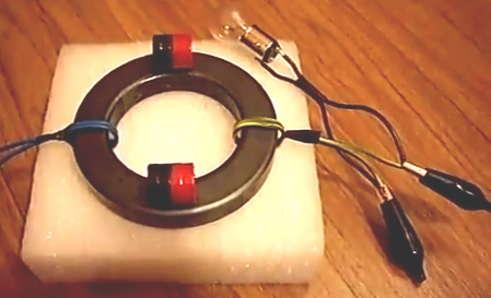 It is probably worth remembering that adding a magnet to a toroid or closed-loop core transformer can boost the output provided that the permanent magnet is not strong enough to saturate the core completely and prevent oscillation of the magnetic flux. This has been shown by Lawrence Tseung, Graham Gunderson and others, and so it might be worth while to experiment further with these configurations along the lines shown in the video here. The Easiest Version: Alexkor has produced a simplified Lenz-law-free design, using commercial toroids already wound as step-down mains transformers. One supplier is here with transformers of this type on offer:  The technique is to remove the plate covering the central opening and connecting the 220V and 110V windings in series. Two of these transformers are used, each of them connected with their 220V and 110V windings wired in series and then the toroids either placed side by side or alternatively stacked on top of one another with a 1 millimetre thick sheet of plastic between them. In the configuration where the toroids “A” and “B” are placed side by side, a power extraction winding “D” is wound between them:  In the case where the toroids “A” and “B” are arranged in a stack with 1 mm plastic sheet between them, the power extraction winding “D” is wound around the two toroids, enclosing them both:  While the winding “D” is shown as a narrow strip in the diagram, that is only to make the drawing easier to understand as in reality, the winding “D” is continued all the way around the whole of the circumference of the toroids and it can be many layers deep to suit the desired output voltage. Toroid “A” has a tuning capacitor “C1” which is adjusted in value to achieve resonance in that circuit as that minimises the current flowing into toroid “A” from the mains. Toroid “B” has a capacitor “C2” which is adjusted to give the highest output voltage (typically 600 volts) coming from toroid “B”. The purpose of toroid “B” is to divert the reverse magnetic flow in Toroid “A” and so, produce an efficient working system. The load “L” is in theory, a dummy load, but in reality there is no reason why it should not be considered to be an actual working load if that output is convenient to use. The output winding “D” is free of the Lenz law effect and the input current from the mains is not affected in any way when the current draw from coil “D” is increased, or even short-circuited. Alexkor stresses the fact that as the toroids are supplied already wound, this is actually a very easy design to replicate.   The Self-Powered Generators of Barbosa and Leal In July 2013, two Brazilian men, Nilson Barbosa and Cleriston Leal, published a series of patents which appear to be very significant. Their patent WO 2013/104042 published on 18th July 2013, is entitled “Electromagnetic device for Capturing Electrons from the Ground to Generate Electricity” and has some very interesting features. It describes a simple device which they describe as an “electron trap”. Their patents are written in Portuguese and an attempted translation of three of them is included at the end of the Appendix. An unusual feature of this design is the fact that it has a continuous conductive loop, in which it is claimed, current flows continuously, even without the need for an applied voltage. Instead, it is the magnetic fields of electromagnets which keep the current flowing. They state that an insignificant amount of input power produces a substantial power output, and they consider a COP of 100 to be about the minimum performance which can be expected from the design. That is a 1 watt input for a 100 watt output. One version of the electron trap looks like this:  The inventors describe their device like this: “this electromagnetic-field-generating device, powered by a power source, produces an electromagnetic field which induces an electric current in a closed conductive circuit, creating an interaction between the magnetic poles of the equipment and the magnetic poles of the earth - through both electromagnetic attraction and repulsion. An endless supply of electrons is drawn from the earth into the conductive closed loop, which is connected to the ground through a conductive interconnected grid. The attracted electrons add to the current already flowing in the conductive closed loop, making power available for driving high-power loads, although the device itself is supplied with only a small amount of power.” One very interesting feature is that the continuous-loop coil formed by wire 4 in the diagram above, is literally, only two turns of wire. The power-gaining mechanism, amazingly, is the earth wire (shown in blue) which is merely wrapped around wire 4 and not directly connected to it as the electron-transfer link is by induction. With this arrangement, the current circulating in the closed loop wire 4, attracts more electrons from the ground, flowing through the wrapped connection of wire 5, into wire 4, augmenting the current flow there by a major amount. Wire 3 can have an alternating voltage applied to it in order to get alternating current in wire 4, but please understand that the current flowing in wire 4 is not the result of the current in wire 3. If the current in wire 3 is DC, then the current in wire 4 will be DC as this is not a conventional transformer, but instead, it is an electron trap, operating in an entirely different way. The electron trap can be connected in an AC circuit of this type:  Here, the earth wire 5 is wrapped around the continuous loop wire 4, feeding it additional electrons captured from the ground. The ends of wire 4 are connected together to form the loop, and that connection also forms the positive side of the output (where a DC output is being produced). The magnetic field produced by the current flowing in wire 3, acts on the electron flow coming from the earth, but as it does not provide any of the electric power flowing in wire loop 4, the current flowing in wire 3 can be tiny, without affecting the power output. In their patent WO 2013/104043, also of 18th July 2013, they show several different ways of connecting their electron trap in a useful circuit. For example, like this:  Here, the battery 13, is used to power an ordinary inverter 12, which produces a high alternating voltage, in this case, at very low power. That voltage is applied to the wire 3.1 to 3.2 of the electron trap, creating an oscillating magnetic field, which creates an oscillating inflow of electrons into the closed loop wire (4), which creates an amplified electrical output at the same frequency – typically 50 Hz or 60 Hz as those are the common mains frequencies. That amplified power output from the electron trap 14, is passed along wire 18 to an ordinary diode bridge 10, and the pulsing DC from the bridge is smoothed and used to replace the battery input to inverter 12. The battery is now switched out of the circuit and, as well as making the overall circuit self-powered, the power coming from the electron trap is used to recharge the battery if it needs recharging (and/or, perhaps, to charge the batteries of an electric car). Because the electron trap needs almost no input power at all, the input power to the inverter is very small, and so a good deal of additional AC power can be drawn off through cable 17, and used to drive powerful electrical loads, with no electrical power being needed from the battery. Being self-powered, the COP value for the circuit is infinity. Just as there are several different ways of using an electron trap in a circuit, there are several ways of constructing and connecting an electron trap. While it is possible to arrange the components so that the power output is 2-phase or 3-phase, here we will just deal with the ordinary, household, single-phase power supply. The first variation is to use more than one frame. Two frames can be connected like this:  This is the actual drawing from the patent and it presents a slight problem in that it is not physically possible to implement the number 4 wire in the way shown. Each frame will have two complete turns wound on it, although the drawing does not show this. Because of the inaccuracy of the drawing, I am not able to say if the coil turns on frame 2, are in the same direction as those on frame 1. There are four possible ways of winding these 2-turn coils when interconnecting them, so perhaps experimentation can be used to determine which method works best. With this two-frame arrangement, there is just the one earth wire 5, as before, again, it is wrapped around wire 4 rather than being physically connected to it. The continuous wire loop 4 has two ends as before, but there are now two 3.1 wire ends and two 3.2 wire ends. The Portuguese translation programs produce highly questionable results for this area of the patent, but I gather that the inventors intend the two 3.1 ends to be connected together and the two 3.2 ends to be connected together, and then the joined ends are treated exactly as before, effectively putting the two windings in parallel. One disadvantage of this design is that it is not portable due to the earth connection. Barbosa and Leal deal with this problem in their patent WO 2013/104041 of the same date where they show a method of constructing an electron trap which collects excess electrons from the air. If you feel that there are no excess electrons in the air, then consider the fact that all of the aerial designs in chapter seven all extract and use those electrons. Also, consider the amount of electricity in a lightning strike, where much of the electrical energy comes from the air, and remember that world wide, there are between 100 and 200 lightning strikes every second. The free-electrons-in-the-air electron trap is somewhat more complicated than the earth-wire electron trap, with four pairs of coils (3 and 4) being mounted inside two aluminium hemispheres (1):  The methods for using the air-electrons trap are the same as those for the earth-wire electron trap. An earth-wire video demonstration is here: here with 22 watts producing 6 kilowatts. To further research this invention, try the extensive information available via here. 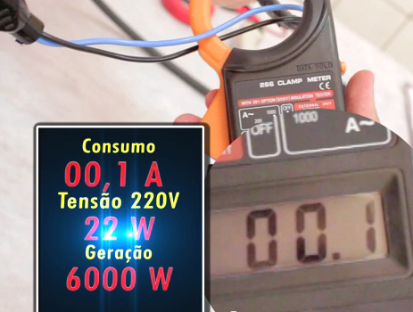 An attempted translation of the three Barbosa/Leal patents is here: ELECTRIC ENERGY GENERATION SYSTEM WITH FEEDBACK Inventors: Nilson Barbosa et Cleriston de Morales Leal  Abstract: The present invention relates to electric energy generation equipment comprising a basic circuit formed by a rectifier (10), for example, an AC/DC converter connected in series to an inverter (12), for example, a DC/AC converter, and a bank of batteries (13) connected in series between the rectifier (10) and the inverter (12). An electron-capturing element (14), which can be either a free space electron-capturing element or, alternatively, an earth electron-capturing element, is connected in series to the basic circuit formed by the rectifier (10), the inverter (12) and the battery assembly (13). The bank of batteries (13) powers the basic circuit because it is connected to the system. Consequently, the inverter (12) converts direct current into alternating current and supplies this current to the electron-capturing element (14). After receiving the electric current from the inverter (12), the electron-capturing element (14) starts capturing electrons from the alternating current and powering the rectifier (10), which converts the alternating current into a direct current in order to recharge the bank of batteries (13) and power the inverter (12) which powers the electron-capturing element, closing the feedback loop, and also providing electric energy for consumption by external loads. WIPO Patent Application WO/2013/104043 Filing Date: 01/11/2013 Application Number: BR2013/000016 Publication Date: 07/18/2013 Assignee: EVOLUÇÕES ENERGIA LTDA (Rua Santa Tereza 1427-B Centro - Imperatriz -MA, CEP -470 - Maranhão, 65900, BR) Technical field The present invention relates to a device for generating electricity, in particular self-powered equipment for generating electricity. Description of the Related Art There are many methods for generating electricity using electromagnetism, but all of these are electromechanical devices using magnets and have limited generating capacity and an ecological impact which makes them unsuited to large scale projects. Objectives of the Invention The aim of this invention is the sustainable generation of electricity, using a generator which is able to produce large amounts of electricity from an extremely low input current, which initially is supplied by a bank of batteries, but subsequently is supplied by the output from the generator which is also able to power external loads. The above objective, and other objectives, are achieved by the present invention through the use of a typical Uninterruptible Power Supply circuit comprising of an AC/DC rectifier feeding a battery bank which powers a DC/AC inverter, which is connected to a device to trap electrons from space (as described in Brazilian patent application No. BR1020120008378 of 13th January 2012) or alternatively, a device which extracts electrons from the Earth (as described in Brazilian patent application No. BR1020120008386 of 13th January 2012), which then passes the extracted electrons to the AC/DC rectifier, charging the battery bank, thus closing the loop as well as providing electricity to power external loads. The self-powered system for generating electricity from the present invention can be fixed or mobile. It is fixed when using electron capture from the earth due to the ground connection, or mobile when using electron capture from space. The self-powered electricity generating system of this invention may be configured in several different ways, each using the same inventive concept but using different arrangements of components. Different versions include single-phase, two-phase or three-phase versions, producing outputs of any power and voltage. Brief Description of the Drawings The present invention will now be described with the aid of drawings, but this patent is not limited to the versions and details shown in these drawings, although they show additional details and advantages of the present invention. The drawings: Fig.1 - shows a basic circuit system for self-powered electricity generation of the present invention  Fig.2 - shows a first embodiment of the constructive system for self-powered electricity generation of the present invention  Fig.3 - shows a second embodiment of the self-powered system for generating electricity of the present invention  Fig.4 - shows a third embodiment of the self-powered system for generating electricity of the present invention  Fig.5 - shows a fourth embodiment of the self-powered system for generating electricity of the present invention  Fig.6 - shows a fifth embodiment of the self-powered system for generating electricity of the present invention; Detailed description of the Invention: There are different ways of closing the self-feeding cycle depending on the circuit configuration chosen. Some of these arrangements are shown in Figures 2 to 6, wherein the main circuitry continues to oscillate, continuously generating instant electricity. As shown in Fig.1, the self-powered system for generating electricity comprises a basic circuit consisting of a rectifier (AC/DC converter) 10 which is connected in series to an inverter (DC/AC) 12. A bank of batteries 13 is connected between the rectifier 10 and the inverter 12. The output from the DC/AC inverter 12, connects to an electron-trap 14 which can extract electrons from space (as described in Brazilian patent application No. BR1020120008378 of 13th January 2012) or alternatively, extracts electrons from the Earth (as described in Brazilian patent application No. BR1020120008386 of 13th January 2012). When connected, the battery bank 13 provides power to the DC/AC inverter 12 which converts the direct current into alternating current and provides current to the electron-trap 14. The output of the electron trap 14 is passed through wire 18, to the AC/DC bridge rectifier 10, which keeps the battery bank charged as well as powering the DC/AC inverter 12. Additional power is passed to external equipment through wire 17.  Fig.2, shows another embodiment of the system of this self-powered electric power generation equipment. It comprises a typical Uninterruptible Power Supply circuit of a battery charger (AC/DC converter) 21 connected to a drive device (a DC/AC inverter) 23 and between them, a battery bank 22 forming the basic circuit. Additional devices are an electron-trap 27 which may collect free electrons from space (as defined in Brazilian patent application No. BR1020120008378 of 13th January 2012) or, alternatively, collects electrons from the Earth (as described in Brazilian patent application No. BR1020120008386 of 13th January 2012). The 3-phase electronic switch 24 normally connects 24.1 to 24.3 connecting the electron trap 27 to inverter 23. Connected in parallel is the surge suppressor 25, which, when activated, via filter 26, causes switch 24 to disconnect the 24.3 to 24.1 link and instead, connect 24.3 to 24.2. An alternative arrangement for use in emergency situations, is to use the system no longer self-powered. For this, the system is comprised of a power input from an external power source, directly to the interconnection point 29 to provide power to surge suppressor 25, which provides power to feed the power output point 28 in order to power external loads. When the electron-trap 27 is turned off, the electronic transfer switch 24 reverts to its default position which connects point 24.1 to point 24.3 causing the circuit to function, once again, in its self-feeding mode. As soon as the electron sensor 27 provides sufficient power to the over-voltage sensor 25, it operates the transfer switch 24 through filter 26, ending the self-feeding phase and supplying energy directly to the power output point 28, in order to feed external loads.  Fig.3 shows another embodiment of the self-powered system for generating electricity, comprising a device which includes the basic circuit of a typical Uninterruptible Power Supply, consisting of a battery charger (AC/DC converter) 31 connected to a drive device (inverter DC/AC) 35 and attached to them, a battery bank 32. This basic circuit together with other devices is connected to an electron-trap 37 for collecting free electrons from surrounding space or, alternatively, an Earth-connected electron trap 37. We have then, a bank of batteries 32 connected to the DC/DC converter 33, which is connected to the phase transfer switch 34 / 34.1 which is connected to point 34.3, which connects to the inverter 35, and so, the electron-trap 37.  Fig.4 shows another embodiment of the system for self-powered electricity generation which is comprised of a basic circuit of a typical uninterruptible power supply, consisting of a battery charger (AC/DC converter) A connected to an inverter (DC/AC) 42 and attached to them, battery bank 41, and this basic circuit together with other devices are connected to a free space electron-capture device 44 or an earth-connection electron-trap 44. Comprising thus, a battery charger A connected to a battery bank 41, which is connected in series with inverter 42 at point B which is in series with point C of inverter 42 which is in series with the electron sensor 44, which is in series with the phase transfer switch 43 via the three-phase load output connection point 45. The phase transfer switch 43 is in series with the inverter 42, which is connected in series the (AC/DC converter) battery charger A feeding the battery bank 41. An alternative construction for use in emergency situations, in which the system ceases to be self-powered, the system may include power input from an external power source, via the interconnection point 46, thus providing electricity output 45, to power external loads. The battery bank 41 provides power to the inverter 42 which converts the direct current into alternating current and feeds the electron trap 44. The phase transfer switch closes when the batteries need recharging. Sensor 44 captures electrons, producing alternating current, which feeds the phase transfer switch 43 with alternating current input power. The phase transfer switch 43 feeds the inverter 42 which charges the batteries, closing the self-powering loop which provides power at the output 45, feeding both the power input and any external loads.  Fig.5 shows another embodiment of the system for self-powered electric power generation equipment comprising a circuit which includes a typical uninterruptible power supply comprising a battery charger (AC/DC converter) 51 connected to a DC/AC inverter 53 and attached to them, a battery bank 52. This basic circuit together with other devices are connected to a space free-electron capture device 56 (as defined in Brazilian patent application No. BR1020120008378 of 13/1/12) or, alternatively, an earthed free-electron collector 56 (as defined in Brazilian patent application No. BR1020120008386 of 13/1/12). This then comprises a battery charger 51 which is connected in series with a battery bank 52, which is connected in series with the inverter 53, which is connected in series with the transformer 55 at its point C, which is in series with its point B which is in series with the electron collector 56, which is in series with the battery charger 51 which is connected to the load exit point 58, which is also the circuit entry point 59, which is in series with the phase transfer switch 54 section 54.1, which is connected to terminal 54.3, which is in series with point A of the transformer 55 which exits at point B. Points A and 54.3 as well as the parallel points 54.1 and 54.2, are all parallel to the battery charger 51, the battery bank 52, the inverter 53 and to point C of the transformer 55. An alternative construction for use in emergency situations, in which the system ceases to be self-powered, the system may include an external power input point 59, allowing phase transfer switch 54 to provide power output 58, to feed external loads. Battery bank 52 provides power to the inverter 53, which converts the direct current into alternating current, feeding point C of the transformer, which comes out at points B and A of the transformer 55. Point B of the transformer feeds the electron-trap 56 producing alternating current which feeds the battery charger 51, recharging the battery bank 52. The battery charger 51 is connected in parallel with the transfer switch 54 via connection points 54.1 and 54.3, feeding point A of the transformer, which comes out at point B. Point A of the transformer and the switch transfer points 54.3 and 54.1 are in parallel to the battery charger 51, the battery 52, the inverter 53 and point C of the transformer 55.  Fig.6 shows another embodiment where a rectifier 61 is connected to an inverter 63 and a battery bank 62, and to a space free-electron trap 64 or alternatively, an earth electron trap 64 comprising thus, a delta (AC/DC) converter 61, which is connected in series to a battery bank 62, which is connected in series with the (DC/AC) inverter 63, which is in series with the electron collector 64 which is connected in series with the delta converter (AC/DC) 61 whose AC part is in series with the alternating AC current inverter 63 via a connecting wire 65 which is in parallel with the DC part of the delta converter 61 with the battery bank 62 and the DC part of inverter 63. An alternative construction for use in emergency situations, in which the system ceases to be self-powered, the system may comprise a power input from an external power source, via the interconnection point 66 connected to the delta converter 61, the output 67 supplying power, to the external loads. Battery bank 62 provides power to the inverter 63, which converts the direct current into alternating current, powering the free-electron collector 64. The captured electrons from collector 64 form an alternating current which feeds the delta converter 61 via an output power load wire 67. The alternating part of the three-phase delta converter 61 is fed with alternating current from inverter 63 via connecting wire 65, which is connected in parallel to the continuous DC delta converter 61, which feeds the battery bank 62 and with the continuous portion the inverter 63, closing the cycle of self-feeding and supplying power at the output 67, which is the output power point. Having described examples of preferred embodiments, it should be understood that the scope of the present invention encompasses other possible forms of construction, using the electron collectors connected to a basic circuit of a typical uninterruptible power supply of energy, known as a UPS, comprising a rectifier device (an AC/DC converter) 10, connected to one inverter (DC/AC converter) 12, and attached between them, an energy storage device (typically, a battery bank). A very important part of the above patent is the device described as a “collector of free-electrons”, either from the earth or from space. We have to go to the patent applications mentioned above to find the details of these designs: Application Number: BR2013/000015, Publication Date: 07/18/2013, Filing Date: 01/11/2013 Assignee: EVOLUÇÖES ENERGIA LTDA (Rua Santa Tereza 1427-B Centro - Imperatriz, MA- CEP -470 - Maranhäo, 65900, BR) Technical Field The present invention refers to electromagnetic equipment for electric power generation or alternatively for thermal power generation. More specifically equipment capable of producing abundant electricity and thermal energy from a tiny amount of input electrical energy. Description of the Related Art According to Lenz's law, any induced current has a direction such that the magnetic field it generates opposes the change in magnetic flux which produced it. Mathematically, Lenz's Law is expressed by the negative sign (-) that appears in the formula of Faraday's Law, as follows. The magnitude of the induced emf (ε) in a conducting loop is equal to the rate of change of magnetic flux (ΦΒ) with time:  As an example of application of Faraday's Law, we can calculate the electromotive force induced in a rectangular loop that moves in or out, with constant speed, a region of uniform magnetic field. The magnetic field flux through the surface limited by the loop is given by:   A conductor traversed by an electric current immersed in a magnetic field undergoes the action of a force given by:  Thus, the effect of the current induced in the loop appears as forces Ff, and F - FM. The first two cancel each other out and the third is cancelled by an external force Pext needed to maintain the constant speed loop. As the force FM must oppose the force Fext, current (i) induced in the loop by varying the magnetic flux must have the meaning indicated in Fig.3. This fact is a particular example of Lenz's Law. Considering the experimental activities discussed with Faraday's law, when a magnet approaches a coil, the induced current in the coil has a direction as shown in Fig.1. This generates a magnetic field whose north pole is facing the north pole of the magnet, that is, the field generated by the induced current opposes the motion of the magnet. When the magnet is moved away from the coil, the current induced in the coil has a direction opposite to that shown in Fig.1, thereby generating a magnetic field whose south pole is facing the north pole of the magnet. The two poles attract each other, that is, the field generated by the induced current opposes the movement of the magnet away from the coil. This behaviour is present in all current power generators, and known as ‘engine brake’ is highly undesirable as it increases the resistance and so, the energy loss. When two electromagnetic coils are placed facing each other, as shown in Fig.2, there is no current in either of them. At the instant of power-up of one of the coils, the current in the coil, generates an induced current in the second coil. When powered up, the current in the coil goes from zero to its maximum value, and then remains constant. Thus, when the current is changing, the magnetic field generated by it, (whose north pole faces the second coil) is also changing and so the magnetic flux of this field through the second coil is also changing. Then there is a current induced in the second coil whose sense is such that the magnetic field it generates tends to decrease the flow mentioned above, that is, its north pole confronts the north pole of the first field coil. When the power switch is opened, the current in the first coil drops from its maximum value to zero, and correspondingly its magnetic field decreases. The flux of the magnetic field in the second coil also decreases, and the induced current now flows in the opposite direction. This current flow direction produces an enhancing magnetic field, that is, it has a south pole facing the north pole of the field of the first coil. Thus, there is a realisation of the principle of conservation of energy, expressed by Lenz's law, wherein any induced current has an effect which opposes the cause that produced it. Assuming that the induced current acts to favour the variation of the magnetic flux that produced the magnetic field of the coil, it would have a south pole facing the north pole of the approaching magnet, causing the magnet to be attracted towards the coil. If the magnet were then released, it would experience an acceleration toward the coil, increasing the intensity of the induced current and thus create an enhanced magnetic field. This field, in turn, would attract the magnet with increasing force, and so on, with a continuing increase in the kinetic energy of the magnet. If energy were to be withdrawn from the magnet-coil system at the same rate at which the kinetic energy of the magnet increases, then there would be an endless supply of energy. So it would be a perpetually operating motor, which would violate the principle of conservation of energy. Therefore, it can be concluded that current generators feature a large energy loss during the generation of electricity. Objectives of the Invention An objective of the present invention is to contribute to the generation of sustainable energy, proposing an electromagnetic machine capable of producing abundant electricity from an extremely low input of electrical energy. The above objective and other objectives are achieved by the present invention by a device comprised of at least one electromagnetic field-generating device (without a core or with at least one core) powered by an electrical power source (without a core or with at least one core) having their coils, or sets of coils, wound on at least one common conductive member in a closed circuit which itself has a polarised voltage which is connected to at least one conductive interconnection element which is connected to a grounding grid, these interconnections creating a new technical effect, namely, the appearance of an electric current which keeps circulating in a closed conductive loop, and which can therefore be used to power external loads. The device which is the object of the present invention operates as follows: the electromagnetic field generating device, powered by a power source, produces an electromagnetic field which induces an electric current in a closed conductive circuit, creating an interaction between the magnetic poles of the equipment and the magnetic poles of the earth - through both electromagnetic attraction and repulsion. An endless supply of electrons is drawn from the earth into the conductive closed loop, which is connected to the ground through a conductive interconnected grid. Attracted electrons add to the current already flowing in the conductive closed loop, making power available for driving high-power loads, although the device itself is only supplied with a small amount of power. Thus, advantageously, the device which is the object of the present invention, acts as a trap for electrons from the earth and this allows the generation of electricity. Advantageously, the present electromagnetic equipment generates either electricity or thermal energy, providing access to this new source of energy is through an electromagnetic field. The interconnections of the components of the electron-trap of the present invention, cause an advantageous new technical effect, namely, the appearance of an electric current which keeps circling in the conductive closed circuit, with or without voltage being applied and even without a load being connected to the loop - provided that the electron-trap is connected. The proposed sensor can also be used to generate thermal power, depending on the form in which you want to use the effect of the flow of electrical current produced in this electromagnetic equipment. For the generation of thermal energy in amounts proportional to the power of the electron-trap, through the movement of electrons in the conductive closed loop itself, the resistance should be increased by increasing the number of turns around the cores in the conductive element of the closed circuit, and in that instance, the coils of the electromagnetic field generating device, will then be made of heat-insulated electrical circuit components, bearing in mind the required temperature which is to be produced. The thermal energy generated by the electron-trap can be used in any application from domestic to industrial applications. This technology can also be used for various technical purposes in electric machines. By "electrical machines", it should be understood to include: static electrical machines, transformers, ballasts, rotating electrical machines, synchronous machines, dual power supply machines, current rectifiers in synchronous cascade, external pole machines, synchronous current machines alternating current machines and/or direct current machines, electronic equipment and electrical resistances. The capture of electrons can provide single-phase, two-phase or three-phase supplies, operating at low, medium or high voltage. The capture of electrons by induction, does not impact on the environment. The fact is that we use as the capturing force, only a negligible amount of electricity relative to the current captured by the sensor. The relationship between power input and the quantity of electricity generated by the electron-trap is at least 1 to 100, that is, for each 1 watt provided to the sensor, there is at least 100 watts of power available for external loads. This relationship, however, is not limited, as it depends on the mounting of the electron-trap and the objectives of the circuit, and so, the generated power can be greater than 100 times the input power. Another advantage of the earthed electron- trap proposed in the present invention is that the electron-trap can transport electrons from point "A" to point "B" without a voltage drop across the closed-loop conductive element - if it is biased with a voltage - regardless of the distance between the points depending on the strength and quantity of the electromagnetic field generating devices. It is also possible to transport electrons when the conductive element in a closed circuit is itself not polarised. Thus, the electric current is transported without voltage, just by the magnetic field formed between the device and the generator of the electromagnetic field. Brief description of the Drawings The present invention will now be described with the aid of drawings, but the design is not limited to the implementations shown in these drawings, although they show other details and advantages of the present invention. The figures show:  Fig.1 - illustrates Faraday’s law.  Fig.2 – is a representation of Faraday’s law.  Fig. 3 – is a representation of Faraday’s law.  Fig. 4 - is a perspective view of an electron-trap with a single phase coil.  Fig.5 – is a perspective view of a single-phase electron trap with two coils.  Fig.6 - is a representation of the effect of electromagnetic flux in the coils around the cores of the electron trap.  Fig.7 - is a representation of an electrical circuit with two coils of the link/coil conductor polarised.  Fig.8 - is a representation of an electrical circuit with two coils of the link/coil conductor not polarised. Detailed Description of the Drawings Fig.4 shows one of several types of electron-trap proposed by the present invention, where the electron-trap is single-phase and consists of at least one electromagnetic field-generating device with at least one set of coils, in this case it happens to be an electromagnetic type coil with one common magnetic core, but it could alternatively have any number of windings of any kind and shape. However, the electron-trap proposed by the present invention can be constructed with a different type of electromagnetic field generating device, such as an electromagnetic inductor or magnet of any type or shape, or any combination of them, and in unlimited numbers for each phase of the electron trap. When winding these coils, for example, coil 4-4, each coil must have at least one complete turn, preferably two turns if the objective is to generate electricity, and preferably four turns if the objective is provide thermal energy. The number of turns in the coils wound around the common core, is directly related to the amount of current to be generated. At least one conductive interconnection element, in this case the driving member 5 - which can be copper or any other suitable conductive, material whether insulated or not insulated, connects or loop-links wire 4 to the ground grid. The connection between the conductor 5 and wire 4 is by electromagnetic induction. Winding 4 is also the power supply for the loads which are to be powered by the captured electrons. Also in Fig.4, the power wires 3.1 and 3.2 (live phase and neutral) have an input from an external power coil 1 which can be energised from any external source of electricity such as a power grid. The trapped electrons can be configured to supply DC or AC current. Thus, if the coil 1 power source is alternating electrical current - AC, then the electron-trap provides alternating electrical current. If the power source is continuous electrical current - DC, then the electron-trap provides continuous electrical current - DC. The electrical supply provided by the trapped electrons can be single-phase, two-phase or three-phase, and at low, medium or high voltage. Fig.5 shows an electron-trap with two single-core phase coils: 1 and 2, although these coils may be of any type and shape. However, the electron-trap proposed by the present invention can be constructed with other types of electromagnetic field generating device, with at least one electromagnetic inductor or electromagnet which can be of any type and shape, with any combination of them, and in unlimited quantities in each phase of the electron-trap. The coils on frames 1 and 2 may have other shapes, but they must each have at least one complete turn, particularly in coil 4. The number of turns in this winding are directly related to the amount of current to be generated. This coil also makes the interconnection between the coils 1 and 2 forming the link between their two cores. At least one conductive interconnection element, in this case the driving member 5 - which can be copper or any other suitable conductive, material whether insulated or not insulated, connects or loop-links wire 4 to the ground grid. The connection between the conductor 5 and wire 4 is by electromagnetic induction. In electron-traps which have numerous sets of coils 1 and 2, the ends of all of the power-supply conductors 3.1 can all be connected to each other, and all of the 3.2 conductor ends may be connected together. Thus, all of the coils 1 and 2 can be fed exactly the same voltage. The power to energise coils 1 and 2 can be provided from any external source of supply of electricity such as a power grid. In electron-traps which have numerous coils 1 and 2, a single coil winding 4 connects the cores of all of the coils 1 and 2. The diagram shown in Fig.6, illustrates the magnetic induction 6 around the core "X" of the coil 1. This induction causes electrical current flow in the conductor coil link 7/4, attracting electrons from the earth, through the conductive member 5, to the magnetic field of the electron-trap, where those electrons are added to the current generated by induction in the link coil 4 conductor loop circulating between north and south magnetic poles. Fig.7 shows how the connections should be made in one version of the electrical circuit of the electron-trap proposed in this invention. The diagram shows the electrical circuit of an electron-trap where the link/coil driver 4 is polarised with a voltage. This is one form of construction for an electron-trap which has two coils 1 and 2, where a link/coil loop conductor 4 is biased with a voltage, that is, there is a link connecting the coil conductors 4 of a power supply 3.1 or 3.2, whatever the stage. In this way, earth electron-traps, by adopting this circuit, that is, with the link/conductor loop 4 and polarised voltage on coils 1 and 2, besides being used as a power source for external loads, can also be used for thermal power generation. Fig.8 shows how connections should be made in another electric circuit electron-trap proposed in this invention. the circuit illustrates a circuit of an electron-trap with a non-polarised link / coil driver 4. This is one form of construction of the electron-trap where a link / coil conductor 4 of the spiral conductor coils 1 and 2 is not polarised, that is, there is no such link connecting conductor / conductor coil conductors 4 of a coil 3.1 or 3.2. Thus, earth electron-traps adopting this circuit, that is, with the link coil not polarised, the current flows without there being voltage in the link/coil conductor 4 joining the first and second coils by electromagnetic induction. They can also be used for generating thermal energy. The structure of the circuit - in the open or closed coils 1 and 2, and always in the closed link / loop lead 4 - makes it possible to generate current by induction and electron capture by electromagnetism on the link conductor 4 - where current is generated and stays in motion with or without voltage, as the coils 1 and 2 are being fed. Thus, the present invention provides a new concept for electrical energy generation, since it is obtained from an electric current circling without consumption and even without an output load being attached to it. Additionally, because the induced electrical current flows regardless of the voltage present, it can be used as a current stabiliser for electrical networks whether they be single-phase, two-phase or three-phase, with low, medium or high voltage. SPACE ELECTRONS TO GENERATE ELECTRICITY Application Number: BR2013/000014 Publication Date: 07/18/2013 Filing Date: 01/11/2013 Assignee: EVOLUÇÕES ENERGIA LTDA (Rua Santa Tereza 1427-B Centro - Imperatriz -, MA - CEP -470 - Maranhão, 65900, BR)  Abstract The invention relates to a device that comprises at least three sets (A, B, C, D) of at least one device for generating an electromagnetic field (3) and (4), powered by an electricity source (without a core or with at least one core) the cores thereof or any extension thereof, preferably the windings or sets of windings thereof, being surrounded by at least a single conductive element forming a polarised and energised closed-circuit (5), the sets of electromagnetic-field generating devices (3) and (4) being linked together by their opposing poles to encourage the interaction of their electromagnetic fields, which ideally, are located between two hollow metal hemispheres (1) so as to concentrate and enhance the electromagnetic fields, these interconnections causing, as a novel technical effect, the emergence of an electrical current that circulates, with or without voltage, in the conductive element forming a closed-circuit (5) - even if no load is connected. Description FROM SPACE, FOR ELECTRICITY GENERATION" Technical Field The present invention relates to electromagnetic equipment for electrical power generation and/or thermal power generation. More specifically, equipment capable of producing abundant electricity and thermal energy from a tiny input of electrical energy. Description of the Related Art According to Lenz's law, any induced current has a direction such that the magnetic field it generates opposes the change in magnetic flux that produced it. Mathematically, Lenz's Law is expressed by the negative sign (-) that appears in the formula of Faraday's Law, as follows. The magnitude of the induced emf (ε) in a conducting loop is equal to the rate of change of magnetic flux (ΦΒ) with time: As an example of application of Faraday's Law, we can calculate the electromotive force induced in a rectangular loop that moves in or out, with constant speed, a region of uniform magnetic field. The magnetic field flux through the surface limited by the loop is given by: A conductor traversed by an electric current immersed in a magnetic field undergoes the action of a force given by: Thus, the effect of the current induced in the loop appears as forces Ff, and F - FM. The first two cancel each other out and the third is cancelled by an external force Pext needed to maintain the constant speed loop. As the force FM must oppose the force Fext, current (i) induced in the loop by varying the magnetic flux flux must have the meaning indicated in Fig.1. This fact is a particular example of Lenz's Law. Considering the experimental activities discussed with Faraday's law, when a magnet approaches a coil, the induced current in the coil has a direction as shown in Fig.2. This generates a magnetic field whose north pole is facing the north pole of the magnet, that is, the field generated by the induced current opposes the motion of the magnet. When the magnet is moved away from the coil, the current induced in the coil has a direction opposite to that shown in Fig.2, thereby generating a magnetic field whose south pole is facing the north pole of the magnet. The two poles attract each other, that is, the field generated by the induced current opposes the movement of the magnet away from the coil. This behaviour is present in all current power generators, and known as ‘engine brake’ is highly undesirable as it increases the resistance and so, the energy loss. When two electromagnetic coils are placed facing each other, there is no current in either of them. At the instant of power up one of the coils, the current in the coil, generates an induced current in the second coil. When powered up, the current in the coil goes from zero to its maximum value, and then remains constant. Thus, when the current is changing, the magnetic field generated by it, (whose north pole faces the second coil) is also changing and so the magnetic flux of this field through the second coil is also changing. Then there is a current induced in the second coil whose sense is such that the magnetic field it generates tends to decrease the flow mentioned above, that is, its north pole confronts the north pole of the first field coil. When the power switch is opened, the current in the first coil drops from its maximum value to zero, and correspondingly its magnetic field decreases. The flux of the magnetic field in the second coil also decreases, and the induced current now flows in the opposite direction. This current flow direction produces an enhancing magnetic field, that is, it has a south pole facing the north pole of the field of the first coil. Thus, there is a realisation of the principle of conservation of energy, expressed by Lenz's law, wherein any induced current has an effect which opposes the cause that produced it. Assuming that the induced current acts to favour the variation of the magnetic flux that produced the magnetic field of the coil, it would have a south pole facing the north pole of the approaching magnet, causing the magnet to be attracted towards the coil. If the magnet were then released, it would experience an acceleration toward the coil, increasing the intensity of the induced current and thus create an enhanced magnetic field. This field, in turn, would attract the magnet with increasing force, and so on, with a continuing increase in the kinetic energy of the magnet. If energy were to be withdrawn from the magnet-coil system at the same rate at which the kinetic energy of the magnet increases, then there would be an endless supply of energy. So it would be a perpetually operating motor, which would violate the principle of conservation of energy. Therefore, it can be concluded that current generators feature a large energy loss during the generation of electricity. Objectives of the Invention The present invention aims to contribute to the generation of sustainable energy, proposing electromagnetic equipment capable of producing abundant electricity from an extremely low input of electrical energy. The above objective and other objectives are achieved in the present invention by a device comprising at least three sets of at least one electromagnetic field generating device (without a core or with at least one core) powered by an electrical power source, having their cores or any extension of them, with their coils or sets of coils, wound on at least one common conductive member in a closed circuit which is polarised by a voltage source, and these sets of electromagnetic field generating devices are arranged with their poles in confrontation, to promote the interaction of electromagnetic fields, and, preferably, positioned between two hollow metallic hemispheres, in order to focus and enhance their electromagnetic fields - these interactions cause a new technical effect - the emergence of an electric current which keeps flowing in a closed loop, with or without voltage being applied to that closed loop, current which is capable of powering external loads - even if no load is attached to it. The device which is the object of the present invention operates as follows: Sets of electromagnetic field generating devices to be powered by an electrical power source, produce an electromagnetic field which induces an electric current in a closed conductive circuit, creating an interaction between the magnetic poles, and through repeated electromagnetic attraction and repulsion, provides an endless supply of electrons to the conductive closed loop itself. The electrons attracted by this technique, augment the current flowing in the closed conductive loop, which provides the current to power external loads of high power, in spite of the fact that the device itself is supplied with only a small level of power. Thus, advantageously, the device which is disclosed in the present invention forms a trap for electrons from space, resulting in the generation of electricity. The interconnections of the components of the electron-trap cause, a new technical effect, namely, the appearance of an electric current which keeps circling in a closed circuit, even without any voltage being applied to the closed circuit, and even without a load being connected to it. The present electromagnetic equipment generates electricity or thermal energy, providing access to this new source of energy through the use of an electromagnetic field. The proposed sensor can also be used for the generation of thermal energy depending on the form of circuit which is to be used, resulting from the flow of electric current produced by this electromagnetic equipment. This field generates a flow of electric current induced by electromagnetic coils, which appears in the linking interconnecting devices generating electromagnetic fields with electromagnets, inductors or magnets. This chain operates in a manner favourable to the variation of the magnetic flux produced by the magnetic field in the electron-trap. Thus, it creates a north pole and a south pole, providing an endless supply of electric current without resistance between the links which interconnect the devices which are generating the electromagnetic fields. So, induced electric current is generated with or without voltage in the interconnection links of electromagnetic field-generating devices, depending on the connection method of the electrical circuit of the electron-trap. The free-electrons collected by the space electron-trap can form alternating current (AC) or direct current (DC). The ratio of input power to output power is 1 to 100, that is, the generated power can be 100 times greater than the input power when there is at least one link / coil driver between the coils and the inductors or electromagnets. This relationship, however, is not limited to a factor of 100, as it depends on the shape of the electron-trap and its objective. Another advantage of the free space electron-trap of the present invention is that, with thermal insulation of the components in the electric circuit, it is possible to produce thermal energy at low, medium or high temperature, through the movement of the electrons in the conductors, coils and/or electromagnets. The temperature generated is linked directly to the number of turns in the coils. Thermal power generation performed by the sensor can be used for boiling and/or evaporation of liquids to be used in other types of energy generation, for example, replacing the use of coal and natural gas. Another advantage of the proposed electron-trap of the present invention is that the electron-trap can transport electrons from one point "A" to a point "B", without a voltage drop in the link - if it is polarised - regardless of the distance between the points, depending on the strength and quantity of the electromagnetic field-generating devices. It is also possible to transport the electrons when the link devices generating the electromagnetic field are not polarised. In this way, the electric current is conveyed without voltage but only by the magnetic field formed between the coils. This methodology can be used in various fields. Because of its simple construction, the electron-trap is a simple device which is compact, and performs low-cost power generation which can be used in all types of machinery, equipment and devices of all kinds, and many areas of application which require electricity in order to operate. The electron-trap can have single-phase, two-phase or three-phase output, and can generate electric current at low, medium or high voltage. Brief description of the Drawings The present invention will now be described with the aid of drawings, but the design is not limited to the implementations shown in these drawings, although they show other details and advantages of the present invention. The figures show: Fig.1 - illustrates Faraday’s law Fig.2 illustrates Faraday’s law where a magnet approaches a coil of just one turn.  Fig.3 is a view of one metallic hemisphere seen from above.  Fig.4 is a bottom view of the hemisphere with the coils in place.  Fig.5 is a side view of the free-space electron-trap.  Fig.6 is an underside view of the space electron-trap, with its coils and electromagnets.  Fig.7 a view from above of the space electron-trap with its coils and electromagnets.  Fig.8 is a perspective view of an electron-trap with its coils. Fig.9 shows the circuit diagram of the device, indicating the effect of electromagnetic field.  Fig.10 - shows the circuit diagram of the connection of the inductor coils in sets (A, B, C and D).  Fig.11 - is an electromagnetic diagram representation of north and south poles of the sets of coils (A, B, C and D).  Fig.12 is a representation of the electrons being attracted and repelled by the device. Detailed Description of the Drawings Fig.3 is a top view of one of the two hollow metallic hemispheres 1 which is part of the electron trap of free space proposed in this invention. Hemisphere 1 is preferably made from, but not limited to, aluminium, and it has mounting tabs 2. Fig.4 is a bottom view of metallic hemisphere 1. It has four electromagnetic field generating devices 3, positioned around the hemisphere and fixed to support 6 which is attached to hemisphere 1 by mounting tabs 2. Fig.5 is a side view of the free space electron-trap. It shows the two metallic hemispheres 1 and 2 (which form an imperfect sphere), and three of the coils 3 which are attached to the mounting tabs 2 and three inductors 4 which form the closed circuit itself, and which are attached by conductors 5, and support member 6 on which are mounted coils 3 and their components. Fig.6 and Fig.7 show the top and bottom views of the metallic hemisphere 1 which accommodates four coils 3 attached to the holder 6 (not shown) which is secured to the hemisphere 1 by its mounting tabs 2. Fig.6 also shows the inductors or electromagnets 4 their corresponding coils 3 and their interconnecting conductors 5. Each coil 3 and its linked inductor 4 forms a set. In Figures 6 and 7 there are four such sets, marked A, B, C and D. The coils 3, connected by their links 5, each have at least one turn, and if the objective is to generate electricity, then preferably two turns, and if the objective is thermal energy, then four turns. The coils 3 may have various different shapes. The number of turns in the coil 3 are directly related to the amount of current to be generated, and the connecting links 5 may be either a single conductor or more than one conductor, the cross-sectional area of conductor 5 being selected to carry the current which is to be generated. In sets A, B, C and D, the link conductors 5 have at least one turn around coils 3. This winding is connected to the respective electromagnets 4 of each set (A, B, C and D) as shown in Figures 6 and 7. Please note that the inductors and electromagnets 4 can be any type of inductor, and other types of coil may be used. Fig.8 shows the inter-connecting coils 5 for each of the five sets A, B, C or D linking between coils 3 and 4 in each set. As shown in Fig.6 and Fig.7, the link 5 makes the connection between coils 3 and 4. This means that the wires marked 5.1 are all connected together, and the wires marked 5.2 are all connected together. Doing this, establishes the interconnection links 5 shown in the drawings. The power supply wires marked 7.1 are connected together as are the wires marked 7.2. The wires marked 7.1 are connected to the live phase of the external power supply, while the other ends marked 7.2 are connected to the neutral of the external power supply. In the space free-electron trap of the present invention, the coils 3 can be either single-phase, two-phase or three-phase. Also, the coils 3 may be powered by any voltage (V). The power coil 3 can be energised by any source of electrical energy such as a power grid. The electron-trap can be configured to produce alternating current or direct current. So, if the external power supply is alternating electrical current - AC, then the electron-trap provides an alternating electrical current output. If the power supply is DC, then the electron-trap provides an output of continuous electrical current - DC. The electron-trap can be configured for single-phase, two-phase or three-phase operation, with low, medium or high voltage outputs. Fig.9 shows an electron-trap circuit diagram with four sets A, B, C and D of inductor coils 3 and 4. Induction is produced around core 9 of the three sets of coils A, B, C and D. The effect of the interaction of the electromagnetic fields 11 is shown. The induction via core 9, causes the circulation of electric current in the links 5, attracting the free electrons through the electromagnetic field of the trap. Then, the electrons join with the current generated by induction on link 5, circulating between the magnetic poles north-south and south-north. By way of example, the coils 3 are shown wound on a single phase column type core, but these can also be of any kind or shape. The electron-trap proposed by the present invention can be constructed with another type of electromagnetic field generating device which has at least one electromagnetic coil or magnet or electromagnetic inductor which can be of any kind or shape, or any combination of those, and with any number in each phase of the electron-trap. The electron capture occurs through an electromagnetic field which is formed with the connection of coils 3 with the electromagnets or inductors 4 through the links 5 between the eight components This closure produces the displacement of the electrons in the coil 3 set (A) (for simplicity, referred to as coil 3A), these electrons are attracted by the protons of coil 3D, and are repelled by the electrons of the electromagnetic field of the coil 3D itself. These coil 3D electrons are attracted by the protons of the coil 3B, and are repelled by the electrons of the electromagnetic field of coil 3B. These electrons of coil 3B are attracted by the protons of coil 3C, and are repelled by the electrons of the electromagnetic field of the coil 3C itself. Similarly, the 3C coil electrons are attracted by protons of the 3A coil, and are repelled by the electrons of the electromagnetic field of the coil 3A itself. These coil 3A electrons are attracted by the protons of the 3D coil, and are repelled by the electrons of the electromagnetic field of the 3D coil itself. Analogously, the coil 3D electrons are attracted by the protons of the coil 3B, and are repelled by the electrons of the electromagnetic field of the coil 3B itself. These 3B coil electrons are attracted by the protons of coil 3C, and are repelled by the electrons of the coil itself induced 3C, and then the coil 3C electrons are attracted by protons of coil 3A, and are repelled by the electrons of the electromagnetic field of the coil 3A itself. That cycle continues as the sets of coils A, B, C and D are being fed by a voltage. These endless attractions and repulsions generate an electric current in the link coil 5. In the electron-trap, the voltage is stable. Regardless of the amount of current generated-which can be very high, the voltage will be the same in the electric circuit of the sensor, because the current moves through the attraction and repulsion of the electrons, regardless of voltage. Fig.10 illustrates a circuit diagram of the electrical connection between the coils 3 and 4 in sets A, B, C and D. It can be seen that the sets A, B, C and D are enclosed between the coils 3 and their associated inductors or electromagnets 4. The supply conductors 7.1 and 7.2, of sets A, B, C and D must be interconnected. When feeding power to the coils 3 and 4 the phase should be connected to 7.1 and the neutral to 7.2. The sets A, B, C and D after being fed with electric current, generate voltage through the attraction and repulsion of the electrons in the linking coil 5, where there is at least one output load 8.1, which should be connected joining sets A and C, and at least one load output 8.2, which should be connected joining sets B and D. The output points 8.1 and 8.2 are the respective phases and neutral of power points 7.1 and 7.2. In this way, a singl-phase electron-trap is created by two pairs of sets of coils/inductors 3 and 4. The 3/4 electromagnet coil set can be replaced by a 3/3 coil set, without any disadvantage to the electron-trap. Sets A, B, C and D, are inserted into a hollow metal hemisphere 1 preferably constructed from - but not limited to - aluminium. The hemisphere 1, whose function is to concentrate and maximise their electromagnetic fields, simulating an electron cloud, has a fixed support 6 connected to attachment tabs 2, and to which the coils 3 are fixed. Fig.11 is a diagram of the electromagnetic north and south poles of the inductor coils 3 and 4 of sets A, B, C and D of the electron-trap. The electromagnetic behaviour described for Fig.9 is again demonstrated by the formation of the magnet assembly to the North Pole and South Pole being attracted and repelled by the lines of force of the magnet from the point "A" to point "D", point "A" to point "B", the point "B" to point "C", point "C" to point "A", and so on, as long as there is an electromagnetic field. The electromagnetic field of the space electron-trap provides that induced current in a direction similar to the variations of the magnetic flux that produced it. So, the magnetic field creates a north pole and a south pole in each of the sets A, B, C and D, as shown in Fig.11. By feeding the coils 3 of the electron-trap with a desired voltage a magnetic field is generated in coils 3, between the four sets A, B, C and D, which form a flow of electrons. This flow of electrons augments the electron flow which is circulating in the closed-loop link-coil 5, thus implementing free electron capture from space. The electromagnetic field of the coil 3A runs north to south, the electromagnetic field of the coil 3B runs north to south, the electromagnetic field of the coil 3C flows from south to north, and the electromagnetic field of the coil 3D flows from south to north, as shown in Fig.11. It should be noted that the sets A, B, C and D can be formed by any combination of coil, magnet and electromagnet. The south to north electromagnetic field induces current flow in the coil 3A. The north to south electromagnetic field induces current flow in the coil 3B. The north to south electromagnetic field induces current flow in the coil 3C and The north to south electromagnetic field induces current flow in the coil 3D. The induced current flow can have any power and it can be single-phase, two-phase or three-phase current. Fig.12 shows the electrons being attracted and repelled by the induction coils 3 and 4. Being repelled and attracted by electromagnetic induction, the electric current flows without resistance. The electron-trap produces electromagnetic waves which can be used for various purposes, including signal transmission at any frequency and for any purpose. The capture is caused by these electromagnetic waves. The same physical effect can be achieved by the combination of the capture devices of other technologies, including electromechanical, electric, electronic, electromagnetic, or through the combination of a magnet or any other magnetised materials. The space free electron-trap of the present invention is a renewable source of electrical power production and a new way of generating energy through the capture effect, generating flows of electrons, generating ordered movement of electrons - electric current - as shown in Figures 9, 11, and 12. Electrons can move without any voltage difference in the continuous loop 5. Alternatively, the loop may be biased with any chosen voltage. The relevant Barbosa and Leal patents in Portuguese can be downloaded here: http://www.free-energy-info.tuks.nl/Barbosa1.pdf http://www.free-energy-info.tuks.nl/Barbosa2.pdf http://www.free-energy-info.tuks.nl/Barbosa3.pdf. The First Barbosa and Leal Replication While many people have tried to replicate the Barbosa and Leal power generator design which draws power from the Earth, and failed. One man whose forum ID is “Clarence” read the relevant patents and knew immediately how the design works and what items in the patents are misdirection by Barbosa and Leal. He has built his own implementation of the circuit and it works perfectly. He has generously shared the relevant details. Please understand that what follows is not a description of where to start experimenting, but instead it is an actual working design. Build it as described and it will work. Build it differently and it won’t work. Clarence has this to say: In the Barbosa and Leal patent they make a vague reference to the Lenz Law. It just so happens that this is the key to the whole device. On the overunity forum, a circuit diagram posted by member “ZeroZero” showed the exact and complete method of defeating the Lenz Law, although most forum members did not seem to understand the importance of the circuit. However, I knew immediately that Lenz’s Law was just another name for back-EMF. The Lenz Law effect is overcome by winding the single primary coil in a clockwise direction and the AWG #4 2.5 turn windings are wound on the bare core in an anti-clockwise direction and that totally negates the Lenz Law. What does this achieve? It gets rid of the voltage component in the secondary windings, leaving only the amperage component! When you wind two toroids exactly the same using this method and connect them as shown below, you create a loop similar to a horseshoe magnet with a keeper on it and the amperage in the loop just goes on circulating round and round as shown by Ed Leedskalin. This is the same principle. The loop has the ability within itself to add unlimited amperage, instantaneously to the neutral green Ground Return wire accordingly as the load requires. The only limit to the available amperage is the current-handling capacity of the looped black wire. You can touch the black wire loop connections with bare hands because as there is no voltage, there is no resulting shock. The connecting of the AWG #10 phase wire to the bottom loop wire only serves to orient the polarisation of the amperage. The oriented spinning of the amperage in the loop induces the amperage needed by the load, into the Captor output. This little toroid can allow the loop to load an AWG #4 wire enough to melt it !! The toroid primary wires Live to Live and Neutral to Neutral should be powered from the inverter by a separate circuit Another separate circuit should be used with the Live connected to the bottom black looped wire in order to polarise it. The Neutral powers the input to ground. The return ground rods are linked in a series loop and then, from a convenient ground rod to the green 2.5-turn loop around the black captor loop and then on to serve as the captor Neutral to the load. You will know that you have enough ground rods when the Captor rms output voltage matches the rms voltage of the inverter, and then, you will probably have to add about another ten ground rods in order to keep the rms voltage of the Captor output from dropping. If the Captor rms output voltage drops – simple – add more ground rods. Please understand clearly that without sufficient ground rods, the apparatus just will not work. Here is a connection pattern where many earthing rods are used:  The circuit diagram from ZeroZero shows this arrangement:  The direction of winding is vitally important as are the wire sizes. You will notice that the windings on the two magnetic frames are in opposite directions, and, the thick wire loop windings are both in opposite directions, and, the thick wire winds also oppose the thin wire winding on the same frame. Looking from above, the thick wire forms the shape of the numeral 8. The thick wire is AWG #4 with a diameter of 5.19 mm and the other core windings are AWG #10 with a diameter of 2.59 mm. The “polarising loop” is produced by taking a few turns of the AWG #10 wire around the insulation of the AWG #4 wire – the wires inside the cables are not actually joined together. The input and output are marked as “mains” as either 110V or 220V can be used, however, not actually fed from the mains as that would create a ground loop, but instead, the input is from an inverter. The earth wire is AWG #6 with a core diameter of 4.11 mm. While the magnetic frames above are shown as rectangular, they are actually circular toroids (which was what Barbosa and Leal used but failed to mention). The ones used by Clarence are type TD300 1120 toroids with a diameter of 5.2 inches (132 mm) and a thickness of 2.3 inches (58 mm) each weighing 6.2 pounds (2.8 Kg) and available from www.tortran.com. Clarance remarks that building this power generator replication is not cheap and he has spent more than US $2000 on his replication. Mind you, with an output power of 3 kW, this unit meets all of his household electrical requirements. It is said that all builders should get a global or national Geomagnetic Map of their area before building, but Clarence says that he is in a “dead” area anyway, so there is probably little point in this as the number of earthing rods needed in your area is found by trial anyway, and knowing in advance does not change that number.  Another edition of the circuit diagram is:  Here are some pictures of Clarence’s successful build: 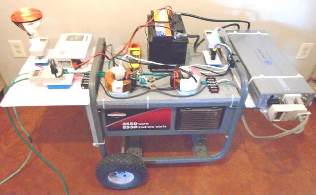 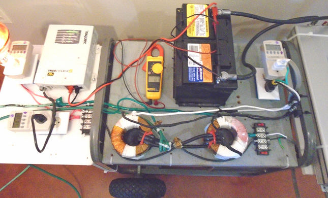 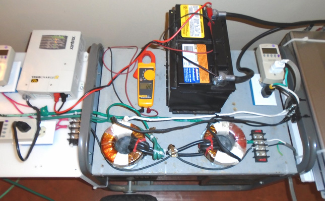 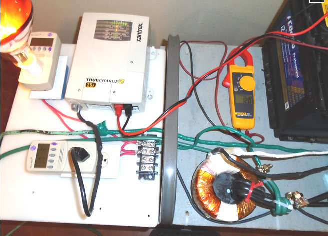 Components used were: Toroids: ----------- Bridgeport Magnetics : Tortran: www.tortran.com Contact: Michael Kharaz E-mail: sales@bridgeportmagnetics.com Tortran Division- Contact us - Bridgeport Magnetics Group Custom ordered toroid (2 required): TD300-1120-P, 300VA, 60Hz, Primary 120V, 160 degrees winding on toroid surface, no secondary winding - $125 USD each Smart Battery Charger: -------------------------------- Xantrex TrueCharge2 Battery Charger - 20Amp model Website: www.xantrex.com Xantrex Dealers list: Where to Buy - N. America Available from Amazon.com: Amazon.com: Xantrex 804-1220-02 TRUECharge2 12V 20A Parallel Stackable Battery Charger: GPS & Navigation Looks like the price is around $260 to $300 USD - depending where you order from. Minimum recommended battery bank size for use with the 20Amp Charger model is 40 Ah 12V Pure Sinewave Power Inverter ------------------------------------------------- AIMS POWER 3000 Watt 12VDC Pure Sine Wave Power Inverter - Model: PWRIG300012120S Website: http://www.aimscorp.net/3000-Watt-Pu...-Inverter.html Available from: InvertersRUs - $699 USD http://www.invertersrus.com/aims-pwrig300012120s.html Amazon - $799 USD http://www.amazon.com/AIMS-Power-PWR...+wave+inverter Forum moderator “Level” who has done an excellent job of retrieving and displaying Clarence’s material here: www.energeticforum.com, says: Stick to the battery and inverter method as the power source, as that is the only way you can avoid a ground loop to the mains electrical power system. The one exception is you might be able to avoid such a problem when powering from the mains if you use an isolation transformer, but isolation transformers can be expensive and have a limited capacity as well. Caution: Also beware that an inverter with an output of 120 volts or 240 Volts can kill you if you touch live wires, so don't build such a setup if you don't understand such things. You need to take necessary safety precautions. Ultra-simple Free energy System from Lorrie Matchett The style of operation used by Barbosa and Leal looks as if it is related to the developments of Lorrie Matchett. On 16th June 2008, Lorrie Matchett published his very simple design for a device which captures usable free-energy (video: YouTube). His device is based on a very simple and well-know principle of static electricity. This is a principle which is taught in schools all around the world but is generally considered to be of no importance as static electricity is considered too low-power to be of any use. I seriously doubt that anyone who has been struck by lightning would consider static electricity to be “low-power” and suggesting that to them is likely to expand your vocabulary with some words which are seldom heard. Important Note: the following details mention the use of mains voltages and so let me stress that this presentation is for information purposes only and must not be construed as being a recommendation that you construct or use any such device. Should you choose to ignore this and construct and use Lorrie Matchett’s device, then please be fully aware that you do so entirely at your own risk and nobody else is in any way responsible for the results of what you do. The principle which is being used here is that an electrically charged object causes the migration of opposite charges on the surface of any object brought close to it. For example if a charged surface if brought close to a metal sphere, then this happens:  The ordinary metal sphere “B” which has no particular charge on it is very much affected by being close to a charged surface “A” and the closer it gets, the greater the effect. The surface of the sphere had an even distribution of positive and negative charges on its surface, giving it an overall charge of about zero, but the charged surface changes all that. The positive charges on surface “A” attract the negative charges on the surface of the sphere causing them to migrate towards surface “A”. While the positive charges on surface “A” do repel the existing positive charges on the surface of the sphere, the migrated negative charges of the sphere itself have an even greater effect, causing the segregation of electrical charges shown above. The situation returns to normal if the sphere is moved away again. However, the situation changes considerably if the metal sphere “B” is connected to the ground:  The movement of charges on the surface of the sphere is the same as before, but the Earth has millions of spare charges of both kinds and so, immediately siphons off the excess positive charges on the side of the sphere away from charged surface “A”. You will notice that charged surface “A” is not directly involved in any way and no charge moves from “A” to “B”. The same effect is seen if the surface “A” is negatively charged (except for the fact that the sphere has positive charges rather than the negative charges shown above. The only current flow is along the wire connecting the sphere to the earth connection. Lorrie Matchett uses this principle, and for the charged surface he connects one end of a brass rod to the ‘Live’ side of a 100V 60 Hz mains electricity supply. The other end of the brass rod is not connected to anything else. This produces this situation for 8.3 milliseconds:  And then for the following 8.3 milliseconds the mains reverses and you get this situation:  The result of this is that there is a backwards and forwards flow of static electricity along the earth connecting wire, a flow which reverses direction sixty times per second. This is not conventional electricity but is the same form of electricity which is collected by an aerial. Nikola Tesla’s patents show many different ways of utilising this static electricity, as does Herman Plauson in his patent (www.free-energy-info.com/Chapter7.pdf). Thomas Henry Moray produced fifty kilowatts of continuous power from quite a small aerial. Paul Baumann of the Swiss commune produced several kilowatts from static electricity. Lorrie Matchett settles for just a few watts and he does it like this: He connects the live wire of a 110V (RMS) AC mains supply to a brass rod 28-inches (710 mm) long and 3/16 inches (4.76 mm) in diameter. The rod is not directly connected to anything else and so does not form part of a closed loop circuit and so, no current flows from the mains. It must be stressed that the rod and connecting wire are potentially very dangerous and need to be insulated very carefully to ensure that touching them will not cause an electric shock. Please understand very clearly that as no current of any kind is drawn from the mains that this circuit is not “stealing electricity from the mains”. For convenience, and only for convenience, Lorrie uses the earthing system of the house mains supply by connecting a green earthing wire to the earth pin of his mains plug. It needs to be clearly understood that this has nothing directly to do with the mains supply and any good quality separate earth would be at least as good as the earthing point inside the mains plug. Effectively, there is only one mains connection. Instead of using a metal sphere as shown in the illustrations above, Lorrie uses a coil of wire wound around the insulation layer on his brass rod, and he passes the alternating flow of static electricity, drawn from the earth, through a standard diode bridge as shown here:  Lorrie covers the brass rod with insulation which is as thin as possible. He suggest heat-shrink tubing for the insulation and on top of it he winds 0.405 mm diameter, solid-core enamelled copper wire, covering a 24-inch (610 mm) length of the rod, placing the turns closely side by side and leaving 2-inches (50 mm) clear at each end of the rod. Thicker wire should not be used. He also shows a 500 milliamp fuse in the mains supply line. I am not at all happy about that as that fuse can power five incandescent 100-watt mains bulbs connected in parallel, and do you really want that amount of power flowing through you if your insulation is not good enough and you touch it? If you use a fuse in that position I would suggest a 20 mm glass quick-blow 100 mA fuse (mainly because no smaller one is readily available). The fuse is not needed for the circuit and is there in an attempt to protect careless humans. The coil wound on the insulated brass rod is only connected at one end and that end goes to one of the two “Alternating Current” tags on a 3A diode bridge. Lorrie does not specify the voltage rating for the diode bridge, but it needs to be a minimum of 170-volts if the mains is a 110V (RMS) type, and double that for a 220V (RMS) mains connection. I have no idea why he specifies a 3-amp rating, but the minimum bridge available locally at 3-amps which I would recommend is a 400V rated unit which is supplied at trivial cost. We need to understand the effect of the diode bridge. It halves the available voltage and doubles the frequency as illustrated here:  A 110V supply is supposed to swing from Minus 155V to Plus 155V and back again sixty times per second, which is an overall voltage swing of 310V. When passed through a diode bridge that changes to a voltage waveform which swings from Zero volts to Plus 154V and back again 120 times per second, which is an overall voltage swing of 154V which is an average or “RMS” voltage of 109V due to the sine wave shape. In the rest of the world, the mains voltage is 220V (RMS) nominal, alternating fifty times per second and the Live mains wire is colour coded brown in the UK and the earth wire yellow/green stripes. In passing, the Neutral wire is white for the American 110V system and blue for the 220V system used in the UK. This design has been brought to my attention by Jes Ascanius of Denmark who is a very able developer of all kinds of free-energy designs. He has replicated this design of Lorrie Matchett and confirms that it works. He has also taken the design further and shares some of the practical details which he has discovered through his own experimentation: For greater power, additional rods can be used:  While brass is considered to be the best material for the rod, the diameter is not critical in any way and any size from 5 mm to 20 mm can be used and instead of a rod, a length of brass pipe should be quite suitable. It is also possible to use other materials for the rod but doing that reduces the output power available. Jes has checked the output of his implementation with the mains fuse removed. The result was an output voltage of 2.6V picked up from the many 220V 50Hz signals generated by the mains wiring all around the place for lighting and sockets. When the fuse is inserted, the voltage rises immediately to 129V with two rods or 162V with five rods. When that voltage is loaded with a 7-watt LED lighting array, the voltage gets pulled down to 61V, but good lighting is being produced for zero current draw from the mains. I would expect that putting a reasonably large capacitor across the load, that the reservoir effect of the capacitor would improve the LED output. Jes initially used two long rods wound with coils:  And later, five rods. His AC ammeter is sensitive enough to show that due to inefficiencies caused by the tiny stray capacitance between the rods and the coils, there is a very slight current draw from the mains. The mains wattage is far less than the output wattage of the system. An improvement implemented by Jes is adding four high-speed BYV27 diodes to the ordinary diode bridge like this:  This has the effect of improving the action of the diode bridge and allows more power to extracted from each cycle of the energy flow. When using two brass rods, Jes gets his 5-watt LED array to light up like this: 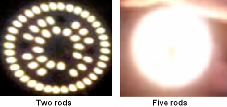 Lorrie also extended his development to a remarkable 48 rods: 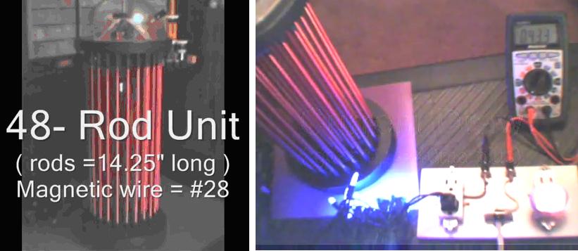 Video link. The electrical output could be used to charge batteries. Adding extra turns does not increase the output voltage. If the number of turns in each coil matches the output load, then the output power will be greater Alexkor in Russia, who is expert in recharging batteries has experimented with this concept and he uses ten coils connected in parallel. He does not use brass, but instead uses the much shorter 300 mm long, 3 mm diameter welding rods with their chemical coating removed. Also, these rods are only used to raise the effectiveness of two separate coils wound on each rod. Each coil is 700 to 750 turns of 0.4 mm diameter wire and the connections are made to the coils and not the rods, as shown here for a single coil pair :  Alex isolates his set of 10 coil-pairs inside a short length of plastic piping:  and uses them to power his battery-charging circuit:  Some people claim that these Matchette style circuits just draw power from the mains. I do not believe that that is the case (although there is a very small leakage caused by the slight capacitance between the coils and the rods, and that is indeed, charged for by the electricity supply company. For drawing power from the mains, a circuit like this is used:  Here, the output voltage is determined by the number of turns in the coils and the available current is controlled by the number of rods involved:  You will notice that these circuits have connections only to the mains and nowhere else. These are not circuits which I use, nor do I recommend that you use it either. The green bars are iron welding rods with the chemical coating removed. These are then wound with a single layer of 0.5 mm diameter enamelled copper wire – that is swg 25 or AWG 24 size wire (a power hand screwdriver is said to be good for coil winding like that). The side-by-side wire coil is then coated with shellac or high-voltage varnish. I am told that with 220V mains power and a 1A diode bridge, that power can be drawn from the circuit without anything being recorded on the electricity supply meter. This is a seriously dangerous circuit as it can produce high voltage at the output of the bridge and that power could kill you. No power drain is recorded, presumably because the coils are wound in opposing directions. Now that is a circuit which could be considered to “steal” power from the mains. The Matchett style circuit is different in that the power flows through the circuit from the ground. Barbosa and Leal demonstrated 169 kilowatts of power flowing from the ground, and as they powered their circuit from a battery-driven inverter and not the mains, there was definitely no question of ‘stealing’ mains power. The battery input also allowed them to establish the actual performance as 104 times more energy flowing out of their circuit than the energy flowing into it. Actually, I’m not at all convinced that the circuit shown above does actually draw net power from the mains. The mains meter charges you for power assessed by multiplying the average voltage by the average current, even when those two are out of step and you receive less power than you are charged for. In this instance, if no current draw is registered on the meter, then perhaps as a result of the opposing direction coils, the power drawn is matched by an equal amount being returned to the mains and there may not be any real net current draw. Either way, I do not recommend the use of these circuits. Theodore Annis & Patrick Eberly have produced a variation on this multiple-magnetic-path method which is shown in their US Patent Application 20090096219. They have opted to use a motionless reluctance switch which is a solid-state device which can block magnetic flow when energised. They have arranged one of their devices like this:  The ring shown in grey is a magnet which connects to the ring shown in yellow through two diagonal ‘reluctance’ (magnetic flow) switches. The yellow ring can carry magnetic flux and the control box marked 118 switches the diagonal strips on and off in turn, causing the magnetic flux to reverse it’s direction through the yellow ring. The coils wound on the yellow ring pick up this reversing magnetic flux and pass it out as an electric current. While only one pair of rings are shown here, the design allows for as many rings as are needed to be connected together as shown here:  The patent says: "The currently preferred motionless reluctance switch is described by Toshiyuki Ueno & Toshiro Higuchi, in their paper entitled "Investigation of the Dynamic Properties of a Magnetic Flux Control Device composed of Laminations of Magnetostrictive Piezoelectric Materials" - University of Tokyo 2004. As shown in Fig.4, this switch is made of a laminate of a Giant Magnetostrictive Material 42, a TbDyFe alloy, bonded on both sides by a Piezoelectric material 44, 46 to which electricity is applied. The application of electricity causes the reluctance of the piezoelectric material to increase.  The full patent application is included in the Appendix. However, very interestingly, there is another, completely different patent application from Annis and Eberly, with the same publication date and the same number. It is not at all obvious to me how that could be, but here is the bulk of that other patent application (the original being in the Appendix) BASED UPON MAGNETIC FLUX SWITCHING Abstract In an electrical energy generator, at least one permanent magnet generates flux and a magnetisable member forms the single flux path. An electrically conductive coil is wound around the magnetisable member, and a plurality of flux switches are operative to sequentially reverse the flux from the magnet through the member, thereby inducing electrical current in the coil. A “Figure of Eight” construction comprises two continuous loops of magnetisable material sharing a magnetisable member common to both loops. An alternative configuration uses stacked loops and a separate piece of material acting as the magnetisable member. One end of the magnet is coupled to one of the loops, with the other end being coupled to the other loop. Each loop further includes two flux switches operated in a 2 × 2 sequence to sequentially reverse the flux through the magnetisable member. A relatively small amount of electrical power is used to control the magnetic flux of a permanent magnet by switching the flux between alternate paths. The resulting power from the switched magnetic flux yields substantially more power than the power required for the input switching. Description FIELD OF THE INVENTION This invention relates generally to energy generation and, in particular, to methods and apparatus wherein magnetic flux is switched through a flux path to produce electricity. BACKGROUND OF THE INVENTION Magnetic flux may exist in “free-space,” in materials that have the magnetic characteristics of free-space, and in materials with magnetically conductive characteristics. The degree of magnetic conduction in magnetically conductive materials is typically indicated with a B-H hysteresis curve, by a magnetisation curve, or both. Permanent magnets may now be composed of materials which have a high coercively (Hc), a high magnetic flux density (Br), a high magneto motive force (mmf), a high maximum energy product (BHmax), with no significant deterioration of magnetic strength over time. An example is the NdFeB permanent magnet from VAC of Germany, which has an Hc of 1,079,000 Amperes/meter, a Br of 1.427 Tesla, an mmf ranging up to 575,000 Ampere-turns, and a BHmax of 392,000 Joules/meter3. According to Moskowitz, “Permanent Magnet Design and Application Handbook” 1995, page 52, magnetic flux may be thought of as flux lines which always leave and enter the surfaces of ferromagnetic materials at right angles, which never can make true right-angle turns, which travel only in straight or curved paths, which follow the shortest distance, and which follow the path of lowest reluctance (resistance to magneto motive force). Free space presents a high reluctance path to magnetic flux. There are many materials which have magnetic characteristics similar to those of free space. There are other materials which offer a low or lower reluctance path for magnetic flux, and it is these materials that typically comprise a defined and controllable magnetic path. High-performance magnetic materials for use as magnetic paths within a magnetic circuit are now available and are well suited for the (rapid) switching of magnetic flux with a minimum of eddy currents. Certain of these materials are highly non-linear and respond to a “small” applied magneto motive force (mmf) with a robust generation of magnetic flux (B) within the material. The magnetisation curves of such materials show a high relative permeability (ur) until the “knee of the curve” is reached, at which point ur decreases rapidly approaching unity as magnetic saturation (Bs) is reached. Some of these non-linear, high-performance magnetic materials are referred to as “square” due to the shape of their B-H hysteresis curves. An example is the FINEMET® FT-3H nanocrystalline core material made by Hitachi of Japan. Other examples include Superperm49, Superperm80, SuperMalloy, SuperSquare80, Square50, and Supermendur, which are available from Magnetic Metals in the USA. A “reluctance switch” is a device or means that can significantly increase or decrease (typically increase) the reluctance of a magnetic path. This is ideally done in a direct and rapid manner, while allowing a subsequent restoration to the previous (typically lower) reluctance, also in a direct and rapid manner. A reluctance switch typically has analogue characteristics. By way of contrast, an off/on electric switch typically has a digital characteristic, as there is no electricity “bleed-through.” With the current state of the art, however, reluctance switches exhibit some magnetic flux bleed-through. Reluctance switches may be implemented mechanically, such as to cause keeper movement to create an air gap, or electrically by various other means. One electrical reluctance switch implementation uses a control coil or coils wound around a magnetic path or a sub-member that affects the path. U.S. Navy publication, “Navy Electricity and Electronics Series, Module 8 -Introduction to Amplifiers” September 1998, page 3-64 to 3-66 describes how to modulate alternating current by changing the reluctance of the entire primary magnetic path by these means, one of which is used in a saturable-core reactor and the other in a magnetic amplifier. Flynn, U.S. Pat. No. 6,246,561; Patrick et al., U.S. Pat. No. 6,362,718; Pedersen, U.S. Pat. No. 6,946,938; Marshall, and US Patent Application 2005/01256702-A1 all disclose methods and apparatus that employ this type of reluctance switch for switching magnetic flux from a stationary permanent magnet or magnets for the purpose of generating electricity (and/or motive force). Another electrical means of implementing a reluctance switch is the placement within the primary magnetic path of certain classes of materials that change (typically increase) their reluctance upon the application of electricity. Another electrical means of implementing a reluctance switch is to saturate a sub-region of a primary magnetic path by inserting conducting electrical wires into the material comprising the primary magnetic path. Such a technique is described by Konrad and Brudny in “An Improved Method for Virtual Air Gap Length Computation,” in IEEE Transactions on Magnetics, Vol. 41, No. 10, October 2005  Another electrical means of implementing a reluctance switch is described by Valeri Ivanov of Bulgaria on the web site www.inkomp-delta.com, shown in Fig.1. An electric toroid 110 is inserted into a primary magnetic path (100), so that the primary magnetic path is divided into two sub-paths 110A and 110B. A net magnetic flux reduction effect in the primary magnetic path 100 results from the combination of the effects in the two sub-paths 110A and 110B, each of which results from different physics principles. In the first sub-path 110A, the magnetic flux generated by applying electrical current to the windings 110 around toroidal path 110 opposes and subtracts from its portion of the magnetic flux 103 received from the primary magnetic path 100 yielding a reduced magnetic flux, which is also further reduced by a decrease in the sub-path 110A's relative permeability thereby increasing the reluctance of the sub-path. In the second sub-path 110B, the magnetic flux generated by applying electrical current to the toroid windings 111 adds to its portion of the magnetic flux 103 received from primary magnetic path 100 yielding an increased net magnetic flux that approaches or exceeds the knee of the material's magnetisation curve thereby reducing its relative permeability and increasing its reluctance. SUMMARY OF THE INVENTION This invention is directed to methods and apparatus where magnetic flux is switched in both direction and intensity through a flux path to produce electricity. The apparatus broadly comprises at least one permanent magnet generating flux, a magnetisable member forming the flux path, an electrical conductor wound around the magnetisable member, and a plurality of flux switches operating to reverse sequentially, the flux from the magnet flowing through the member, thereby inducing electrical current in the coil.  The preferred embodiment includes first and second loops of magnetisable material. The first loop has four segments in order A, 1, B, 2, and the second loop has four segments in order C, 3, D, 4. The magnetisable member couples segments 2 and 4, and the permanent magnet couples segments 1 and 3, such that the flux from the magnet flows through segments A, B, C, D and the magnetisable member. Four magnetic flux switches are provided, each controlling the flux through a respective one of the segments A, B, C, D. A controller is operative to activate switches A-D and B-C in an alternating sequence, thereby reversing the flux through the segment and inducing electricity in the electrical conductor. The flux flowing through each segment A, B, C, D is substantially half of that flowing through the magnetisable member prior to switch activation  The loops and magnetisable member are preferably composed of a nanocrystalline material exhibiting a substantially square BH intrinsic curve. Each magnetic flux switch adds flux to the segment it controls, thereby magnetically saturating that segment when activated. To implement the switches, each segment may have an aperture formed through it and a coil of wire wound around a portion of that segment and through the aperture. The controller may be at least initially operative to drive the switch coils with electrical current spikes. The first and second loops may be toroidal in shape, and the loops may be spaced apart from one another, with A opposing C, and 1 opposing 3, and with B opposing D and 2 opposing 4. The magnetisable member in this case is preferably a separate piece of material. Alternatively, the first and second loops may form a “Figure of eight” shape, with the two loops intersecting to form the magnetisable member. The permanent magnet(s) and the material comprising the magnetic paths are preferably proportioned such that the material through the common segment is at or slightly below its maximum relative permeability before the electrically conducting output coil is energized. In the preferred embodiments, the power resulting from the switched magnetic flux yields substantially more power than the power required for the input switching. BRIEF DESCRIPTION OF THE DRAWINGS Fig.1 is a drawing of a prior art reluctance switch in the form of an electrical toroid inserted into a primary magnetic path; Fig.2 is a detail drawing of a reluctance switch according to the invention; Fig.3A and Fig.3B are detail drawings showing the use of four reluctance switches according to the invention; Fig.4 is a drawing which depicts a preferred embodiment of the invention; Fig.5 is a detail drawing an alternative reluctance switch according to the invention implemented through split laminations; Fig.6A and Fig.6B show the operation of an energy generator according to the invention; Fig.7A is an exploded view of a preferred energy generator construction; Fig.7B is a side view of the construction shown in Fig.7A; Fig.8 is a simplified schematic diagram of components used to simulate the apparatus of the invention; Fig.9A is a diagram that shows the current delivered to one pair of flux switches in the simulation; Fig.9B is a diagram that shows the current delivered to the other set of flux switches in the simulation; Fig.10 shows the output of the simulation shown here; and Fig.11 is a block diagram of a controller applicable to the invention DETAILED DESCRIPTION OF THE INVENTION  Fig.2 is a detail drawing of a reluctance switch according to the invention. The reluctance switch includes the following components: a closed magnetic path 110 comprised of a high performance magnetic material (preferably a non-linear material exhibiting a “sharp knee” as saturation is approached), around which is wound a coil 111. The closed magnetic path 110 shares a common segment 101 with a primary magnetic path 100, in which magnetic flux 103 is induced by a permanent magnet (shown in subsequent drawings). Electric current is applied to windings 111 having a polarity and sufficient amperage so that the magnetic flux generated in the path of switch 110 is additive to the magnetic flux 103 from the permanent magnet, such that the primary path 110 approaches or reaches magnetic saturation.  Fig.3A and Fig.3B are detail drawings of an apparatus which employs four reluctance switches according to the invention in a manner similar to that disclosed in U.S. patent application Ser. No. 11/735,746 entitled “Electricity Generating Apparatus Utilising a Single Magnetic Flux Path”, the entire content of which is incorporated herein by reference. In this and in all embodiments described herein, the geometry of the closed magnetic paths may be circular (toroidal), rectangular, or any other closed-path shapes . A primary path 304 carries the flux from permanent magnet 302 unidirectionally. Flux switch pairs 310 A/E and 310 B/D are activated in alternating fashion to reverse the flux in magnetisable member 304C, thereby inducing electrical current in winding 330. Fig.3A shows the flux flow in one direction, and Fig.3B shows it reversed. In Fig.3A, switches 310A and 310E are activated by controller 320 in electrical communication with the windings on the switches such as through conductor 322 to winding 324. The additional flux in switches 310A and 310E are additive with the flux that would otherwise be present in segments 304A and 304E, thereby saturating these paths, causing the flux through segment 304C to be in the direction shown. In Fig.3B, switches 310B and 310D are activated, saturating segments 304B and 304D, and reversing the flow.  Fig.4 is a drawing that depicts an embodiment of the invention using circular toroids 400, 401 and multiple permanent magnets 402, 403 disposed in the primary path 404. The two toroids 400, 401 intersect, forming magnetisable member 404E. A coil 430 is wound around the member 404E, as shown. The primary magnetic path 404 interconnects the upper end of loop 400 and the lower end of loop 401. One of the magnets, 402, couples one end of the primary magnetic path 404 to the first loop 400, and another, 403, couples the other end of the primary magnetic path 404 to the second loop 401. In this, and all of the embodiments described here, the permanent magnets are strong, rare-earth magnets, and multiple magnets of any length (thickness) may be used in each case. Further, in all embodiments, the loops, primary magnetic path and/or magnetisable member are preferably constructed from a high magnetic permeability material such as the FINEMET FT-3H nanocrystalline soft magnetic material available from Hitachi. The invention is not limited in this regard, however, as alternative materials, including laminated materials, may be used. The connections of the primary magnetic path 404 to the two loops 400, 401 create four segments apart from the magnetisable member 404E, the four segments including two opposing segments A, B in the first loop on either side of magnet 402, and the two opposing segments C, D in the second loop on either side of magnet 403. Four magnetic flux switches are provided, each being operative to control the flux through a respective one of the four segments. A controller 420 is operative to activate the switches associated with segments A and D, and then B and C, alternately, thereby reversing the flux through the member 404E, and so, inducing electrical current in coil 430.  Apertures may be formed through each of the four segments, with the switches being implemented by coils 410A to 410D which pass through the apertures and around an outer (or inner) portion of each segment. As shown in Fig.5, if the loops are fabricated with laminated material 502, the laminations may be split at 506 to accommodate coil 504. The percentage of the segment surrounded by the coil may vary in accordance with the material used, the waveforms presented to the coils, and other factors, with the goal being to magnetically saturate each segment through activation of the associated switch, thereby reversing the flux through path 404E. Fig.6A and Fig.6B show the operation of the apparatus of Fig.4. The primary path 404 carries the flux from permanent magnets 402 and 403 unidirectionally. Reluctance switches 410A to 410D are activated alternately to reverse the flux in segment 404E which, in turn, induces electrical current in winding 430. Fig.6A shows the flux flow in one direction, and Fig.6B shows it flowing in the opposite direction. In Fig.6A, switches 410A and 410D are activated by controller 420 in electrical communication with the windings on the switches, such as through conductors 422 to switch 410B. The flux provided by switches 410A and 410D, thereby saturating these paths, causing the flux through segment 404C to be in the direction shown. In Fig.6B, switches 410B and 310C are activated, saturating segments 404B and 404D, thereby reversing the flux through path 404E.  Fig.7A depicts a preferred construction of the apparatus depicted in Fig.4, Fig.6A and Fig.6B. Loops 400 and 401 are implemented as complete toroids 700, 701. This is important, since preferred high-performance magnetic materials are currently available in regular shapes of this kind. Note that, in this case, curved slots such as 770 are formed through the sides of each toroid to implement flux switches A to D. The magnetisable member in this embodiment is implemented with a block of material 704, preferably the same high-performance magnetic material used to construct loops 400, 401. Permanent magnet 702, shown at 702, preferably has the same length as block 704, enabling the various constituent parts to be held together with compression, shown in Fig.7B. The following sections summarise some of the important characteristics of the preferred embodiments: In terms of materials, the apparatus benefits from the use of nanocrystalline material with a “Square” BH intrinsic curve, a high Br (remanence) which is about 80% of its Bs (saturation), a low Hc (coercivity), and a fast magnetic response time to saturation. An example is FineMet FT-3H from Hitachi of Japan, which has a Br of 1.0 Tesla, a Bs (saturation) of 1.21 Tesla, a time to saturation (Bs) of 2 usec, and an Hc of −0.6 amp-turns/meter. Modern permanent magnets are used with a square BH intrinsic curve, a Br in the range of 1.0 Tesla or more, and high Hc in the range of −800,000 amp-turns/meter or more. An example is the NdFeB magnet from the German company VAC, which has a Br of 1.427 Tesla and an Hc of −1,079,000 amp-turns/meter. An important consideration is the matching of the magnet to the nanocrystalline material, both in Tesla rating and in cross-sectional area. The magnet's Br should be below the Bs of the nanocrystalline material. If the magnet is too “strong” for the nanocrystalline material, this may cause the nanocrystalline material to saturate at the area of contact with the magnet. The current driving the reluctance switches in the prescribed 2 × 2 sequence should have a sharp rise in the leading edge (Tr) of each pulse with a pulse width (Pw) and Amperage value that are sustained until released at the end of the pulse width (Tf). The table below shows the effects of input current pulse rise times (Tr) on the output. There exists a narrow band of Tr, before which there is small power output, at which there are excellent power output and COPs in the range of 200 to 400 or greater, and after which there is no major increase in power output. The COP of this device without the coupling circuit is defined as “Output power/Drive Power” for the switches.  The Motionless Generators of Heinrich Kunel While Richard Willis of Magnacoaster in Canada, has gone commercial with his generators, making each of the generator outputs multiples of 12V 100A, a lot of very interesting earlier information can be found in the 1982 patent of Heinrich Kunel. The patent describes four separate configurations of his basic design, a design which looks very much like that used by Richard Willis. Here is an attempted translation of the Kunel patent which is in German: PROCEDURES AND DEVICES FOR ENERGY PRODUCTION Application Number: DE19803024814 19800701 Priority Number(s): DE19803024814 19800701 IPC Classification: H02N11/00 EC Classification: H02K53/00 DESCRIPTION The invention concerns procedures and devices for energy production, which convert the magnetic flux from permanent magnets, without the need for rotary, or any other form of motion, into temporally variable induced flux and produce large fluctuations of the induced magnetic flux into electric current, without the need for a thermal circuit, or torque or chemical process, and in such a manner that the electric current is amplified. The energy problems of our time are sufficiently well-known in the professional world. The transformation of conventional primary energy forms into technically usable energy is relatively cost-intensive. Additionally, by doing this, precious and ever scarcer raw materials are being destroyed and pollutants are accumulated, pollutants which are able to cause the end of mankind. In order to reduce or avoid these and other disadvantages during power production, it is suggested according to this invention, that for the production of electric current by induction, no torque is used, but instead, the magnetic flux from permanent magnets is converted into an induced flux with large rapid variations, e.g. into a rapidly changing or pulsating induced flux, which can generate an electric current. In accordance with this invention, one proceeds from the basic arrangement where a permanent magnet is connected to an iron core via one or both of its poles, the core consisting of, for example, dynamo iron, pure iron or amorphous iron or any similar suitable material which has little or no core losses. Following the procedure of this invention if, for example, one pole of a bar magnet touches such an iron core and is aligned with the longitudinal axis of that core, then both the magnet and the core act as a magnet. During this initial magnetisation process of the core a magnetic flux flows in the core, which induces a current in a conducting circuit surrounding the core. If, in addition to the permanent magnet, a coil is wound around the core, and arranged in such a way that a current flowing in that coil wholly or partially interrupts the magnetic flux flowing through the core, then this causes another modification of the magnetic flux passing through a coil wound around the core. If this interruption of the flux flowing from the permanent magnet is large, and has the waveform of a Alternating Current, then a pulsating Direct Current is induced in the coil wound around the core. With an AC input to the magnetic flux modifier coil wound on the core beside the magnet, the coil receives two current flow direction changes per AC cycle, and so the magnetic flux coming from the permanent magnet is interrupted once and released once during each input power cycle. In this way, a pulsating induced Direct Current is generated in the output coil caused by the pulsating magnetic flux in the core. It was found that the induced flux from a permanent magnet achieves its full initial value of the magnetic flux density in the core also at the free end of the soft-iron magnetic core, even if there are several induction windings each with the same number of turns and the conductor cross section are appropriate as in a magnetic flux modification coil wound on the core, without changing the strength of the magnetic flux density or the remanence of the permanent magnet. The permanent magnet is not demagnetised when used to provide the flux in the core, no energy is extracted from it, unlike an electromagnetic core, whose windings require more operating current than that produced as an output. With an electromagnetic core, as much input current is required, as is induced in the output winding, corresponding to the relationships of the well-known transformer. Therefore it is important to produce the induction flux by using a permanent magnet. After the basic primary system, one can build e.g. energy linear generators or energy circle generators or other arising or suitable types and forms of energy generators, without the necessity of a rotor or a stator or any such mobile sections or providing torque in the generator. The invention is so designed as to make only frequency control governed by electrical means so that the internal induction flux in the generator core is essentially caused by the magnetic field of the permanent magnet. In the drawings constructional examples are schematically represented according to the invention: Fig.1 shows a linear energy generator in longitudinal cross-section.  Fig.2 shows a linear energy generator in the instantaneous state of the transmission of the induction flux of the permanent magnet to the generator core and  Fig.3 represents a linear energy generator at the moment of the interruption by the induced flux;  Fig.4 explains a static energy pulse generator with a closed magnetic circuit at the moment the transmission of the induction flux of the permanent magnet to the generator core block,  Fig.5 is a schematic diagram of the functional way in which the feedback process operates in a system according to the present invention,  Fig.6 shows a double linear energy generator with some of its sub-elements and  Fig.7 shows an energy generator, according to the present invention, with cyclic pulsing operation and with some of its sub-elements in and at the energy circuit.  The linear energy generator shown in cross-section in Fig.1, consists of a permanent bar magnet 1 with a soft-iron magnetic generator core 2, which can be a single piece, or, as shown here, divided into two sections. The magnetic flux modification coil is not directly attached to the permanent magnet 1, so that the permanent magnet 1 is not subjected to the alternating fields produced by the magnetic flux modification coil 3. On the generator core 2, following the magnetic flux modification coil 3, there are several output coils 4. An air gap 6 serves as a gate or circuit-breaker for the magnetic flux coming from the permanent magnet 1 and the magnetic induction flux for the induction windings 4. With this arrangement, an alternating current applied to the magnetic flux modification coil 3 is used to produce an alternating magnetic field in the air-gap 6, so that, as shown clearly in Fig.2, with each phase of the alternating current the induced magnetic flux 5 is directed first to the core 2 and then against the permanent magnet 1, as shown in Fig.3, causing the magnetic flux 5 induced in core 2 by the permanent magnet 1, is interrupted totally or partially, and thus experiences a modification which varies with time. If an alternating current is supplied to the magnetic flux modification coil 3 e.g. with a frequency by 50 Hz, then the induced flux 5 in core 2 experiences one hundred modifications per second, inducing in the induction windings 4 a pulsating direct current 14 which has 50 positive maximum values per second.  Fig.2 illustrates that on the generator core 2 several induction windings 4 are wound, which correspond to the number of turns with same wire diameter as used in the magnetic flux modification coil 3. The permanent magnet 4 requires no electric current to produce its magnetic flux and nevertheless has at its North Pole end N of the core 2 the same magnetic saturation, as produced by the multiple number of turns of induction coil 4 of Fig.2 or in a continuous coil 4 as shown in Fig.3, receives a multiple version of the input current which is needed for the excitation of the magnetic flux modification coil 3. From the power source 9 the energising current flows to the pulse generator 10, the 1-amp ammeter 20 displays the intensity of the electric current. The induced current 7 or the pulsating direct current 14 is added via connections 11,1 and is measured by the 10-amp ammeter 20,2. The rectifier 15 (not shown) produces pulsating Direct Current which is smoothed and supplied as the DC output 18, through wire 21 to the battery charger 25, which provides the input for the power source 9. The interruption of the magnetic flux by the direction change of the Alternating Current, necessary for the repeated modification of the induction flux 5, is shown in Fig.3. When the induction flux 5 is interrupted, the wire coil(s) 11.2 is negative in that instant. Wire 21 provides the connection to the output power (not shown) and the input power source 9.  Fig.4 shows an embodiment of the above design which uses a U-shaped permanent magnet 1 and a U-shaped generator core 2 which has its two ends facing towards the poles of the permanent magnet 1. Wound around two narrow air gaps 6 and its own narrow core, is a magnetic flux modification coil 6.6. Fig.4 shows the instantaneous state, when the magnetic flux 5 is transferred from the magnetic flux modification coil 3 into the generator core 2 forming a closed magnetic circuit 24. The magnetic flux modification coil 3 here has a core 6.6, which alternately makes and interrupts the passage of the magnetic flux 5 between two narrow air gaps 6 from the permanent magnet 1 to the generator core 2 which has the induction windings 4, so that each pulse of the induction flux 5 induces a current in the induction windings 4. Thus a pulsating Direct Current results which is several times larger than the input energising current. When the direction of current flow in the soft-iron magnetic core 6.6 of the magnetic flux modification coil 3 is changed, then at that time, the magnetic flux 5 of the permanent magnet 1 flows over into the iron guidance block 1.1 and flows along the paths 5.5 and 5.1 to the South-pole of the permanent magnet 1 or to the equilibrium in the air gaps between the North-pole of iron guidance block 1.1 and the South-pole of the permanent magnet 1. The dashed line 5.5 from North-pole to South-pole through the iron guidance block 1.1 depict the magnetic flow when it is prevented from travelling through the generator core 2. This steering of the magnetic flux 5 prevents leakage flux entering the generator core 2 and so the maximum RMS of the induced current is achieved, as the generator core 2 is without magnetic excitation. PJK note: I have difficulty in accepting this as the excitation coil would appear to produce an equivalent magnetic flux into the U-shaped frame 2 as it blocks the permanent magnet flux passing across the air gaps between magnet 1 and electromagnets 3, and to make things worse, magnetic flux flows about a thousand times more easily through soft iron than through air. However, we do know that modulating the flux from a permanent magnet with the magnetic field from a coil is very effective in producing COP>1 as has been shown by the independent replication of Lawrence Tseung’s magnetic frame covered earlier in this chapter. The following schematic diagram Fig.5, shows the sequence in the cyclic process e.g. in an energy generator according to Fig.4. The pulsating current from the power source 9 or Alternating Current 12 from the power-grid 23 flows through wire 13 to the magnetic flux modification coil 3 and produces a pulsating induction current 7 or pulsating direct current 14, which is converted by the rectifier 15 to smooth Direct Current 16 which is passed to the voltage regulator 17, and then on as Direct Current 16 now at the desired voltage, on to the DC output 18 and to the current transformer 10, by which the received Alternating Current 12 is led to the AC output 19 and coupled by AC link 22 with the power-grid input 23, whereby the AC output 19 can be supplied with current from the power-grid or from the electric output of the energy generator.  Fig.6 shows a double linear generator in accordance with the invention. On a preferably straight-line permanent magnet are fitted generator cores 2 of dynamo iron to its two poles. The magnetic flux modification coil 3 gets its working current from the power source 9 through a current transformer or from pulse generators 10 fed by the excitation circuit 13. Through appropriate windings 4 an output of either Direct Current or Alternating Current can be obtained. Pulsating Direct Current 14 from the induction current circuit 11 is smoothed and passed to the DC output 18 and to the input power source 9. A further version of the system in accordance with the invention is shown in Fig.7. This is also a motionless energy producer, although it has a cyclic arrangement and function. In this generator there are no mobile sections such as a rotor and the induction flux 5, like the induction current 7, develops from a cyclically pulsating induction flux. The permanent magnet 1 is inserted into a circular generator core 2. The magnetic flux modification coils 3 can be operated with pulsating Direct Current 14 or as here with Alternating Current 12. For example, the Direct Current 16 from the power source 9 is led into a current transformer 10 converted into Alternating Current and fed into the exciter circuit 13. The magnetic flux modification coils are created so that the positive maximum value of the Alternating Current 12 opens and supports the natural flow of the permanent magnet flux 5 passing from the North-pole to the South-pole through the circular generator core 2 to form a closed magnetic circuit 24. If the magnetic flux modification coils 3 on both sides of the permanent magnet 1 carry the maximum negative value of the Alternating Current 12, then the natural magnetic flux in the generator core 2 is constricted by induction flux moving in the opposing direction in the magnetic flux modification coils 3 and this interrupts the magnetic flux 5 either totally or partially. In the case of temporally large modification of this sequence in the coil 4 a pulsating direct current 14 is caused, which is led by the induction circuit 11 to the electric rectifier 15, in which the pulsating direct current 14 is reduced to a smooth DC current. The Direct Current 16 can be passed to the DC output 18 and the input power supply 9 and the current transformer 10 which supplies the AC output 19 and AC to the magnetic flux modification coils 3. If the induction flux 5 is restricted in the core 2 by the magnetic flux modification coils 3, then an Alternating Current with a smaller negative maximum value is produced and the arithmetic average value during one period shifts down to zero. According to this invention in a cyclic process an energy circle is created, with considerable energy surplus for the supply of the various outputs as well as for the maintenance of the operation of this system. According to this invention, by avoiding the need for torque, the same induction effect is obtained by the magnetic flux modification coils and the use of permanent magnets in energy generation, as with the conventional generators which use the transformation of torque into electricity, whereby however, the energy value of the input torque is greater than the energy value of the electricity this generated. It was found that from each pole of the permanent magnet to the two ends of a U-shaped generator core one of the magnetic flux modification or guidance coils with or without core for transmission of the magnetic induction flux has to be designated in such a manner that by alternating induction flux, which is caused by the permanent magnet e.g. in the rhythm of the phase change of an alternating current frequency of the energising current the generator core is constantly commutated, as the North-pole will be transferred alternating to one and the other open end of the core and the coils likewise leading to the core to s-pole of the permanent magnet close the reversible magnetic circuit in the core with each current pulse, which is caused by a permanent magnet. In this way the induction flux in the core experiences its desired flux direction change and produces in the output windings of the generator an Alternating Current of the same frequency as those of the energising current, however with identical frequency to that of the input energising current. Since the pulsating or reversible induction flux is caused by a permanent magnet, no electric current is necessary for its production also for the whole length of the generator core and its output windings, because the reversible magnetic excitation of the core takes place indirectly in each case or directly via a permanent magnet, whose remanence is changed by the magnetic excitation of the generator core in accordance with the invention. The system according to invention for energy production and energy producer can be extremely efficient e.g. in high frequency operation with electronically controlled direct current pulse operation and it can output a multiple of the necessary input current and electricity be produced in this way, is produced without material being used up and without a thermal circuit or a torque being necessary. If several of these generators are cascaded in graduated increasing size e.g. in a series where the second generator receives the full output from first and third generator receives the full output of the second, then with a power multiplier of 10 for each generator, the sixth generator in the chain will have a 1000 MW performance if there is a 1000 W power input to the first (and smallest) generator at the start of the series. Thus it is possible to replace all well-known primary energies and procedures of the energy conversion with the systems and energy generators according to invention, for all future on economical into electricity because of their high costs, since these cannot operate in any way remotely as economically, as it is possible with the devices of this invention.  Valeri Ivanov’s Motionless Generator. There are other devices which have what appears to be a very important air-gap in a magnetic frame. One of these was displayed on a Bulgarian website and it is on the web page which is located here, put up by Elin Pelin and Valeri Ivanov, dated 2007, and recently translated into English. Valeri lives in Elin Pelin, Bulgaria and his motionless generator has COP=2.4 performance. Videos here and here are for his design, and it appears that he is about to go commercial: www.inkomp-delta.com in May 2014 It is shown that an effective device can be constructed from a permanent magnet, a toroid and a laminated iron yoke. The arrangement is displayed like this:  When the input coil is pulsed with an input voltage, it causes a flux reversal in the frame around which the output coil is wound, generating an electrical output. There is also a forum related to this and the better known MEG of Tom Bearden’s which can be found here where that particular message states that Valeri’s device can be made to work at frequencies as low as 50 Hz and can use standard laminated iron frame components and produces Coefficient Of Performance figures up to 5.4 (that is, the output power is more than five times the input power). A demo video is here but it is not in English. It may well be that in order to work well, the MEG needs a very narrow input coil with an air-gap on each side of it and the same may well apply to Lawrence Tseung’s magnetic frame shown earlier in this chapter. The Motionless Generators of Kelichiro Asaoka Kelichiro Asaoka received US patent 5,926,083 some two years before the well-known MEG patent of Tom Bearden and his associates. Personally, I find it hard to understand how the MEG patent (in the Appendix) could have been awarded when the Asaoka patent was already in place. However, here is most of the content of the Asaoka patent: Static magnet dynamo for generating electromotive force based on changing flux density of an open magnetic path ABSTRACT A static magnet dynamo including at least one permanent magnet having different poles; a first core comprising a soft magnetic material and which couples the different poles of the permanent magnet to form a closed magnetic path; a second core comprising a soft magnetic material which couples to the closed magnetic path via a paramagnetic material to form an open magnetic path; a magnetised coil wound around a portion of the first core where the closed magnetic path is formed; and an induction coil wound around a portion of the second core. A direction of a flux of the closed magnetic path is changed by applying an alternating voltage to the magnetised coil, generating an electromotive force in the induction coil by electromagnetic induction due changes in a flux of the open magnetic path induced by the change in direction of the flux of the closed magnetic path. FIELD OF THE INVENTION This invention relates to a dynamo which generates electromotive force by electromagnetic induction by changing the flux passing through an induction coil. More particularly, this invention relates to a static magnet dynamo that changes magnets that pass through an induction coil without turning the armature or electromagnet. DISCUSSION OF BACKGROUND Dynamos currently in practical use are so designed as to generate electromotive force by electromagnetic induction by changing the flux passing through an induction coil. Dynamos that generate power this way come in a wide variety, ranging from large models used in hydroelectric, thermal or atomic power plants to small models such as small dynamos with a diesel engine. In all dynamo models mentioned above, the armature and electromagnet are turned, to change the flux passing through the induction coil, thus generating electromotive force in the induction coil by electromagnetic induction. For examples, the armature and electromagnet are turned by the torque of a water turbine in hydroelectric power generation, by the torque of the steam turbine in thermal and atomic power generation, and by the torque of the diesel engine in small dynamos. Disadvantages: Dynamos that generate electromotive force by electromagnetic induction as mentioned above are so designed that, regardless of the size of the dynamo, the armature and electromagnet are turned in order to change the flux passing the induction coil. These dynamos are disadvantageous in that the said turning of the armature and electromagnet generates vibrations and noise. OBJECTS OF THE INVENTION The purpose of this invention is to provide a static magnet dynamo devoid of any torque-giving means or other moving part to eliminate vibrations and noise, in order to resolve the various problems mentioned above. To resolve the above problems, this invention is composed as described below. The static magnet dynamo involved in this invention consists of at least one permanent magnet, a first core consisting of a soft magnetic material forming a closed magnetic path by coupling the different poles of the said permanent magnet, a second core consisting of a soft magnetic material forming an open magnetic path by being coupled to the closed magnetic path via a paramagnetic material, a magnetised coil wound around a part consisting of only the closed magnetic path of the first core, and an induction coil wound around the second core. The point of this invention is to generate electromotive force in the induction coil by electromagnetic induction by changing the direction of the flux of the closed magnetic path by applying an alternating voltage to the magnetised coil and by changing the flux of the open magnetic path induced by changes in the direction of the flux in the closed magnetic path. The static magnet dynamo involved in this invention consists of at least one permanent magnet, a first core consisting of a soft magnetic material forming a closed magnetic path by coupling the different poles of the permanent magnet, a second core consisting of a soft magnetic material forming a bypass closed magnetic path coupled and arranged with the first core in such a manner as to include the permanent magnet of the closed magnetic path, a magnetised coil wound around the part consisting only of the closed magnetic path of the first core, and an induction coil wound around the part consisting only of the closed magnetic path of the second core. The aim of this invention is to generate electromotive force in the induction coil by electromagnetic induction by changing the direction of the flux of the closed magnetic path by applying an alternating current to the magnetised coil, and by changing the flux of the bypass closed magnetic path induced by changes in the direction of the flux of the closed magnetic path. Effects: In the above configuration, the static magnet dynamo involved in this invention consists of a first core consisting of a permanent magnet and a closed magnetic path, a second core consisting of an open magnetic path via a paramagnetic material, a magnetised coil wound around the part consisting only of the closed magnetic path of the first core, and an induction coil wound around the second magnetic path. The dynamo is so designed as to generate electromotive force in the induction coil by electromagnetic force by changing the direction of the flux of the first core by applying an alternating voltage to the magnetised coil, and by changing the flux of the second core induced by changes in the direction of the flux of the first core. This makes it possible to change the flux passing through the induction coil without a torque-giving means or other moving part and to generate electromotive force in the induction coil by electromagnetic induction, thus enabling power generation without causing vibrations or noise. This dynamo can also be downsized and made available at low prices. Other characteristics and benefits of this invention will be made clear by the description given below with diagrams attached. BRIEF DESCRIPTION OF THE DRAWINGS A more complete appreciation of the invention and many of the attendant advantages thereof will be readily obtained as the same becomes better understood by reference to the following detailed description when considered in connection with the accompanying drawings, wherein:  Fig.1 represents a basic configuration of a static magnet dynamo with an open magnetic path involved in this invention.  Fig.2 represents how a flux in the direction opposed to that of a permanent magnet typically occurs in the magnetised coil.  Fig.3 represents how a flux in the direction opposed to that of a permanent magnet typically disappears from the magnetised coil  Fig.4 represents how a flux in the same direction as that of the permanent magnet typically occurs in the magnetised coil.  Fig.5 is a first embodiment of the static magnet dynamo involved in this invention.  Fig.6 is a second embodiment of the static magnet dynamo involved in this invention.  Fig 7 is a third embodiment of the static magnet dynamo involved in this invention.  Fig 8 is a fourth embodiment of the static magnet dynamo involved in this invention.  Fig 9 is a fifth embodiment with an open magnetic path.  Fig 10 is a basic configuration of a static magnet dynamo with a closed magnetic path involved in this invention.  Fig 11 is a first embodiment of the static magnet dynamo with a closed magnetic path involved in this invention. DESCRIPTION OF THE PREFERRED EMBODIMENTS Referring now to the drawings, wherein like reference numerals designate identical or corresponding parts throughout the several views, and more particularly to Fig.1 where there is illustrated a basic configuration of the static magnet dynamo with one permanent magnet. Figs. 2, 3, and 4 describe how the static magnet dynamo represented in Fig.1 generates power.  As indicated in the figures, the first core 2 formed to couple the permanent magnet 1 and the different poles of the permanent magnet 1 in an annular manner, forms a closed magnetic path. This closed magnetic path is then equipped with a second core 3 via a paramagnetic material 10 μm to 5 mm thick. This results in the formation of an open magnetic path consisting of a permanent magnet 1, part of a first core 2, a paramagnetic material, and a second core 3. The part consisting only of the closed magnetic path of the first core 2 is wound around with a magnetised coil 4. The second core 3 is then wound around with an induction coil 5 designed to generate electromotive force by electromagnetic induction. Here, the permanent magnet 1 is a magnet with a high residual flux density, a great coercive force, and a large maximum energy product for higher power generation efficiency. Typical materials used here are neodymium iron boride magnet (Nd2Fe14B), samarium cobalt magnet (Sm2Co17), or samarium iron nitride (Sm2Fe17N2). The first core 2 and the second core 3 are made of a soft magnetic material having a high permeability, with high initial, maximum, and other permeability levels, high residual flux density and saturation magnetisation, and small coercive force, thus making effective use of the flux of the magnetic path for power generation. Examples include Permalloy based alloys. Applicable paramagnetic materials are those with a specific permeability comparable to that of a vacuum, such as air, copper, and aluminium. When air is used as a paramagnetic material, that is, when a gap G is secured between the first core 2 and the second core 3, the second core 3 is retained with a solid paramagnetic material. The figures represent embodiments with a gap G, without a solid paramagnetic material designed to retain the second core 3. Following is a description of how a static magnet dynamo of the above configuration generates power. First, when no voltage is applied to the magnetised coil 4 of the static magnet dynamo, a first flux 11 is formed in the first core 2 in the direction going from the N pole to the S pole of the permanent magnet 1. In this state, no flux has been formed in the second core 3 coupled via the gap G.  A voltage can be applied to the magnetised coil 4 in three manners described below. In the first voltage application, as indicated in Fig.2, a DC voltage VS is applied to the magnetised coil 4 in the direction that the voltage repels the first flux 11 of the first core 2 generated by the permanent magnet 1, and vice versa, that is, in such a manner that the second flux 12 occurs in the reverse direction of the first flux 11. As a result, the first flux 11 repels the second flux 12 and vice versa, so that the flux more easily leaks from the closed magnetic path. The first flux 11 and the second flux 12, which more easily leak from the closed magnetic path, jump across the gap G and enter the second core 3, so that a third flux 13 is induced in the second core 3. Furthermore, the induction of this third flux 13 changes the flux passing through the induction coil 5, so that electromotive force V1 occurs in the induction coil 5, resulting in power being generated.  Next, removing the DC voltage applied to the magnetised coil 4 prompts the first core 2 to try going back to a state where only the first flux 11 is formed as indicated in Fig.1. At that time, the second core 3 has a flux in the reverse direction of the third flux 13, that is, the fourth flux 14 indicated in Fig.3, in order to kill the third flux 13. Then, the induction of the fourth flux 14 changes the flux passing the induction coil 5, so that electromotive force V2 occurs in the induction coil 5, resulting in power being generated. Power generation in this first voltage application can be realised by a static magnet dynamo involved in this invention, a DC power supply to apply a DC voltage VS to the magnetised coil 4, and a switching circuit that turns the DC power supply on and off. A contact-less switching circuit can be made if a semiconductor switching device, such as a thyristor, is available. The second voltage application is the same as the first voltage application up to the point where the third flux 13 is induced in the second core 3 by applying a DC voltage VS to the magnetised coil 4 so as to generate the second flux 12 in the reverse direction of the first flux 11 and where the third flux 13 is induced to generate electromotive force V1 in the induction coil 5, thus generating power.  Next, changing the polarity of the DC voltage applied to the magnetised coil 4 generates in the first core 2 the first flux 11 caused by the permanent magnet 1, as well as the fifth flux 15 in the same direction as the first flux, caused by the magnetised coil 4. Here, the first flux 11 is given the fifth flux 15, so that the second core 3 is given the fourth flux 14 as indicated in Fig.4, as well as the sixth flux 16 in the same direction as the fourth flux 14. Furthermore, inducing the fourth flux 14 and the sixth flux 16 changes the flux passing through the induction coil 5, so that an electromotive force V3 larger than the electromotive force V2 is generated in the rotary coil to generate power. This second voltage application requires a polarity switching circuit PSC that changes the polarity of DO voltage instead of a switching circuit that turns on and off the DC voltage applied to the magnetised coil 4 in the first voltage application. This polarity switching circuit can be made of a semiconductor switching device, similarly to the switching circuit in the first voltage application. In the third voltage application, AC voltage VS is applied to the magnetised coil 4 instead of applying DC voltage to the magnetised coil 4 in the second voltage application with the polarity changed. The flux generated by applying AC voltage to the magnetised coil 4 becomes an alternating flux that alternates between the second flux 12 in Fig.2 and the fifth flux 15 in. Fig.4. Then, the flux induced in the second core 3 is the third flux 13 in Fig.2 when the second flux 12 is generated, and is the fourth flux 14 trying to kill the sixth flux 16 and the third flux 19 in Fig.4 when the fifth flux 15 is generated. That is, the flux induced in the second core 3 naturally also becomes an alternating flux. In power generation of this third voltage application, AC voltage is applied to the magnetised coil 4, which overcomes the need for a switching circuit or polarity switching circuit PSC, which was needed in the first and the second voltage application, so that the device becomes simplified. Furthermore, the flux induced in the first core 2 and the second core 3 becomes an alternating flux induced by AC voltage, so that the dynamo functions also as a transformer having a gap G between the first core 2 and the second core 3. It is therefore possible to increase further the electromotive force V generated by electromagnetic induction in the induction coil 5. Next, the power generation efficiency of a static magnet dynamo involved in this invention is described. The static magnet dynamo can be considered as a transformer if its permanent magnet 1 is removed and there is a gap G. A transformer entails an eddy current loss We and hysteresis loss Wh of the core, and a loss Wr due to the electric resistance of the coil. These factors are in a relation formulated below. Let the input be Win and the output Wo, and the Win becomes equal to the total loss, so that the conversion efficiency of the transformer is In reality, in Fig.1, the closed magnetic path consisting of the first core 2 contains a permanent magnet 1. The flux of this permanent magnet 1 therefore contributes to power generation. Therefore, in Fig.1, let the input be Win2 and the output Wo2, then Where Wp represents power resulting from the flux of the permanent magnet 1 contributing to power generation, and α represents a conversion efficiency obtained when the device is considered as a transformer with a gap G. Therefore, power generation efficiency is: Eff = (Wp / Win2) + α . . . . . . . (4) Here, since α < 1, if Wp / Win2 > 1, that is, if power obtained resulting from the flux of the permanent magnet 1 contributing to power generation is larger than dynamo power supplied to the magnetised coil 4, power generation efficiency becomes no less than 1, so that the device can display its performance as a dynamo. Thus, the inventor examined as described below how much the flux of the permanent magnet 1 contributes to the induction of the third flux 13 in Fig.2. First, the inventor provided static magnet dynamos of the basic configuration indicated in Fig.1, one with a permanent magnet 1 and another without a permanent magnet 1. The inventor then compared the power levels needed to induce fluxes of equal flux densities to the second core 3 of each embodiment, that is, the power levels supplied to the magnetised coil 4. As a result, an embodiment with a permanent magnet 1 required only a very low power level to be supplied to the magnetised coil 4. It was observed that the power level required was no more than one fortieth of that of the embodiment without a permanent magnet 1, depending on the test condition. In a static magnet dynamo involved in this invention, therefore, Win2 can be made sufficiently smaller than Wp, so that the inventor considers it possible to make Wp / Win2 > 1. Embodiment 1 Next, as the first embodiment, a static magnet dynamo system composed of two static magnet dynamos of the basic configuration is described based on Fig.5.  In Fig.5A, in a static magnet dynamo, a closed magnetic path is made of two permanent magnets 1 and two first cores 2 formed so as to couple the different poles of one permanent magnet 1 with the other permanent magnet 1 in an annular manner. This closed magnetic path is then equipped with a second core 3 via a gap G. This forms an open magnetic path consisting of a permanent magnet 1, part of a first core 2, a paramagnetic material, and a second core 3.  This open magnetic path can be arranged in two different ways. In one configuration, as indicated in Fig.5A, one open magnetic path can be made of two permanent magnets 1 and two second cores 3. In the other configuration, as indicated in Fig.5B, one open magnetic path can be made of one permanent magnet 1 and another can be made of one first core 2. The static magnet dynamos in Fig.5A and Fig.5B do not differ substantially in terms of effect results, except that their patterns forming such an open magnetic path differ. The part forming only a closed magnetic path of each first core 2 is wound around with a magnetised coil 4. Each second core 3 is then wound around with an induction coil 5 which generates electromotive force by electromagnetic induction. This static magnet dynamo forms a first flux 11 in the first core 2 in the direction going from the N pole to the S pole of the permanent magnet 1, with no voltage applied to the magnetised coil 4. Furthermore, the action of this dynamo applying voltage to the magnetised coil 4 and generating electromotive force in the induction coil 5 by electromagnetic induction to generate power is similar to static magnet dynamos of the basic configuration. The static magnet dynamo with two permanent magnets 1 as mentioned above has well-balanced magnetic paths. Since the flux of the permanent magnets 1 can be effectively used, this embodiment achieves higher power generation efficiency than static magnet dynamos of the basic configuration. The first embodiment is a static magnet dynamo system composed of two static magnet dynamos of the basic configuration. Similarly, a static magnet dynamo system can be made as a combination of three or more static magnet dynamos of the basic configuration (Figs. 1-4). In that case, similarly to the first embodiment, an open magnetic path can be formed in two manners. One configuration is the formation of one open magnetic path by coupling all permanent magnets 1 with a second core 3. The other is the formation of as many open magnetic paths as permanent magnets by coupling the N pole of each permanent magnet 1 to the S pole with a second core 3. Embodiment 2 Next, the second embodiment of the present invention is represented in Fig.6,  the third embodiment in Fig.7  and the fourth embodiment in Fig.8  In these embodiments, the action of applying voltage to the magnetised coil 4 and generating electromotive force in the induction coil 5 by electromagnetic induction is similar to that of a static magnet dynamo of the basic configuration (Figs. 1-4). The second and the third embodiments represented in Fig.6 and Fig.7 have the same basic configuration as the first embodiment, except that the first core 2 in each embodiment is shaped quite differently. In the second embodiment, the part opposed to the end of the second core 3 sticks out toward the end of the second core 3. Thus, the leakage flux due to the repellence of the first flux 11 and the second flux 12 generated in the first core 2 jumps across the gap G and enters the second core 3 with greater ease. Embodiment 3 The third embodiment is so designed that the part coupling the second core 3 is that part of the first core 2 which is nearest to the permanent magnet 1 and, to shorten the open magnetic path even further, the two permanent magnets 1 are close to each other. Since a flux tends to form a closed magnetic path with the shortest distance, the leakage flux due to the repellence of the first flux 11 and the second flux 12 generated in the first core 2 jumps across the gap G and enters the second core 3 with greater ease. Embodiment 4 The fourth embodiment indicated in Fig.8, as opposed to a static magnet dynamo of the basic configuration, consists of a first loop where permanent magnets 1 with multiple closed magnetic paths are arranged circularly with the fluxes oriented in the same direction, and of a second loop which is wound around with a magnetised coil 4 and installed inside the first loop. Furthermore, the parts with their first cores 2 coupling the first loop to the second one stick out toward each other across a specified gap. The parts where this first core 2 stick out are coupled together with a second core 3 via a gap G to form an open magnetic path. This reinforces the flux of the permanent magnets 1 and makes it easier for the leakage flux due to the repellence of the first flux 11 and the second flux 12 generated in the first core 2 to jump across the gap G and enter the second core 3. Embodiment 5 The configuration of a static magnet dynamo involved in this invention has so far been described in terms of embodiments where an open magnetic path is connected to the first core 2 at both ends of the second core 3 via a paramagnetic material. However, this invention is not limited to these embodiments.  That is, as indicated in Fig.9, the open magnetic path may be embodied by extending any two parts of the first core 2 in the direction that they approach each other, thus defining them as core extensions 6, and coupling these core extensions 6 via a paramagnetic material 6'. This embodiment can be applied to all embodiments mentioned above. Embodiment 6  As indicated in Fig.10, a closed magnetic path consists of a permanent magnet 1 and a first core 2 formed so as to couple the different poles of the said permanent magnet 1 in an annular manner. This closed magnetic path is then equipped with a second core 3 so that it comes magnetically in parallel with the permanent magnet 1, so that a bypass closed magnetic path is composed of a permanent magnet 1, part of a first core 2, and a second core 3. The part consisting only of the closed magnetic path of the first core 2 is wound around with a magnetised coil 4. The second core 3 is then wounded around with an induction coil 5 designed to generate electromotive force by electromagnetic induction. The action of a static magnet dynamo of the above configuration generating power is described below. First, when no voltage is applied to the magnetised coil 4 of a static magnet dynamo, the first core 2 forms a first flux 11 in the direction going from the N pole to the S pole of the permanent magnet 1. In this state, a flux similar to that of the first core 2 is generated in the second core 3 as well. Embodiment 7  The seventh embodiment is described below based on Fig.11, in terms of a static magnet dynamo system composed of two static magnet dynamos of the basic configuration and with the relative position of the permanent magnets changed. In a static magnet dynamo, a closed magnetic path is composed of two permanent magnets 1 and two first cores 2 so designed as to couple the different poles of one of the permanent magnets 1 with the other permanent magnet 1 in an annular manner. This closed magnetic path is then equipped with a second core 3. This results in the formation of a bypass closed magnetic path consisting of a permanent magnet 1, part of a first core 2, a paramagnetic material, and a second core 3. The parts where a closed magnetic path of each first core 2 alone is formed are wound around with a magnetised coil 4. Each second core 3 is then wound around with an induction coil 5 designed to generate electromotive force by electromagnetic induction. In this static magnet dynamo, where no voltage is applied to the magnetised coil 4, a first flux 11 is formed in the first core 2 in the direction going from the N pole to the S pole of the permanent magnet 1. The action of applying voltage to the magnetised coil 4 and generating electromotive force in the induction coil 5 by electromagnetic induction to generate power is similar to that of a static magnet dynamo of the basic configuration. In the aforementioned static magnet dynamo incorporating two permanent magnets 1, magnetic paths are arranged in a well-balanced manner. This makes it possible to make effective use of the flux of the permanent magnets 1, so that power generation efficiency is higher than that of a static magnet dynamo of the basic configuration. This invention has so far been described somewhat in detail in terms of the most favourable embodiments. Since it is clear that a wide variety of embodiments can be realised without opposing the philosophy and scope of this invention, this invention will not be limited to any particular embodiment, except for the limitations described in the attached claim. Stephan W. Leben. There is an interesting video posted on YouTube here where a contributor whose ID is "TheGuru2You" posts some really interesting information. He starts with a circuit produced by Alexander Meissner in 1913 and shown here:  Stephan states that he has built this circuit and can confirm that it is a self-resonating powering circuit. Once a twelve volt supply is connected to the input terminals, the transistor switches on powering the transformer which feeds repeating pulses to the base of the transistor, sustaining the oscillations. The rate of oscillation is governed by the capacitor marked "C" in the circuit diagram above and the coil across which it is connected.  Interestingly, if that capacitor is replaced by an electrolyser (which is effectively a capacitor with the water forming the dielectric between the plates of the capacitor), then the frequency of the circuit automatically adjusts to the resonant frequency of the electrolyser and it is suggested that this system should be able to perform electrolysis of water requiring only a low power input and automatically slaving itself to the varying resonant frequency of the electrolyser. As far as I am aware, this has not been confirmed, however, the voltage pulsers designed by John Bedini do slave themselves automatically to their load, whether it is a battery being charged, or an electrolyser performing electrolysis. Stephan then suggests combining Alexander Meissner's circuit with Charles Flynn's magnetic amplification circuit. Here the transformer is switched to become the Charles Flynn oscillator winding plus a second winding placed alongside for magnetic coupling as shown here:  The transistor stage would be self-oscillating as before, the transformer now being made up of the red and blue coil windings. This oscillation would also oscillate the Flynn magnetic frame, producing an electrical output via the black coils at each end of the magnetic frame. This is, of course, an oscillating, or AC output, so the four diodes would produce a full-wave rectified (pulsating) DC current which is smoothed by the capacitor connected to the diodes. This circuit could be started by touching a 12 volt source very briefly to the output terminals on the right. An alternative would be to wave a permanent magnet close to the red and blue coils as that would generate a voltage in the coils, quite sufficient to start the system oscillating and so, becoming self-sustaining. Stephan suggests using the piezo crystal from a lighter and connecting it to an extra coil to produce the necessary voltage spike when the coil is held close to the blue coil and the lighter mechanism clicked. A surprising problem would be how to switch the device off since it runs itself. To manage this, Stephan suggests a two-pole On/Off switch to disconnect the output and prevent it supplying the input section of the circuit. To show whether or not the circuit is running, a Light-Emitting Diode ("LED") is connected across the output and the current flowing through it limited by a resistor of about 820 ohms. Anyone wanting to try replicating this device will need to experiment with the number of turns in each coil and the wire diameter needed to carry the desired current. Stephan states that you need to have at least twice the weight of copper in the (black) output coils as there is in the (blue) input coils in order to allow the device produce excess power. The first page of the Appendix shows the current carrying capacity for each of the standard wire diameters commonly offered for sale. As this is a fairly recently released circuit, I am not aware of any replications of it at this time. Floyd Sweet’s VTA Generator. Another device in the same category of permanent magnets in conjunction with oscillating coils, was produced by Floyd Sweet. The device was dubbed “Vacuum Triode Amplifier” or “VTA” by Tom Bearden. The device was capable of producing more than 500 watts of output power at 120 Volts, 60 Hz requiring less than one third of one milliwatt as input power. The output power can operate AC motors, lights, heaters and when rectified, DC motors. Thanks is due to Horst Weyrich who has recently provided me with links to useful material which I had not seen before. This link: YouTube is to a video in which Floyd shows most of the magnet conditioning process. Recently, some additional information on Floyd Sweet's device, has been released publicly by an associate of Floyd's who goes just by his first name of "Maurice" and who, having reached the age of seventy has decided that it is time to release this additional information. That information can be found in the Appendix. I am not aware of anybody who has succeeded in replicating Floyd’s VTA, but here is as much information as I have at this time. In the above video, Floyd talks about separating two of his conditioned permanent magnets with an “air gap” which is astonishing as he is putting them on opposite sides of a length of aluminium channel with thick walls and aluminium has a major damping effect on magnetic fields:  This arrangement which seems quite mad, is confirmed by a picture from Floyd’s lab. As shown here: 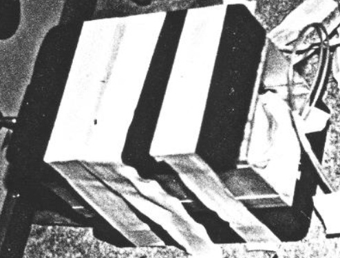 This shows clearly that the open ends of the channel are not between the two magnets allowing an unrestricted magnetic field to flow between them, but instead, two channel thicknesses of aluminium are between the two magnets, obstructing the magnetic flow – quite remarkable !! Floyd shows two coils being used to condition the magnets. The first is the large vertical coil shown here in front of Floyd:  The second coil is not seen as it is inside the vertical coil, sitting flat on the base, and consisting of an entire reel of AWG #17 (1.15 mm diameter) wire, something like this: 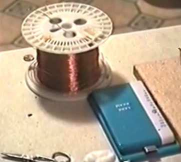 This coil operates effectively as an air-core solenoid, producing a strong axial magnetic field inside the larger coil which surrounds it. This inside coil is driven by a sine wave signal in the 10Hz to 15Hz range, boosted through a 100-watt audio amplifier which provides the current needed to impose the sine wave on this low impedance coil without distorting the waveform. The first step is to determine the resonant frequency of each of the two permanent magnets to be used. The ferrite magnets used appear to be about 6 x 4 x 1 inch (150 x 100 x 25 mm). As they will eventually be used as a pair, one end of each is marked so that they can be aligned in the correct orientation after conditioning. That size of magnet appears to have a resonant frequency of about 12Hz, but each magnet will be slightly different. The inside, low frequency coil is powered up at around 12Hz, the length of the magnet aligned with the Earth’s magnetic field (that is, North/South), and placed on top of the vertical coil. An iron shim as used in transformer core construction is placed vertically on top of the magnet as an indication of resonating: 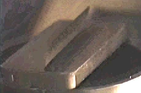 As shown in the video, the sine wave frequency feeding the AWG #17 coil is adjusted slowly to find the point at which the iron shim vibrates most strongly. That frequency is noted, and the same is done for the second magnet. It is not likely that the two resonant frequencies will be the same, and so the average frequency for the pair is used. Next, the two magnets are placed in attraction mode, one on each side of the aluminium channel, with their marked ends at the same end of the channel. That is, the North pole face of one will touch the aluminium and the South pole face of the other will touch the aluminium. The two magnets and their separating aluminium channel are then placed inside the main coil and aligned so that the outer North pole faces southwards and the opposite external South pole faces Northwards. The large coil dimensions are arranged so that the centre of the magnets is at the centre of the outer coil:  While the inner coil continues to be powered up with a powerful sine wave, the outer coil is now fed a 60Hz stream of sharp voltage pulses. These are generated by charging up a 16,000 microfarad 250V capacitor and then discharging it through an SCR (Thyristor) connected to the outer coil. It is important that the spikes be sharp as they are imposing that frequency on the internal magnetic structure of the magnets. Presumably, if aiming for a European 240V version, then the outer coil would be pulsed at 50Hz rather than the American 60Hz and the capacitor would be a 450V rated type. The working pictures of Floyd’s prototype powering a load, seem to indicate that the one input coil and one output coil as described by Ashley Gray below, are the same as used by Floyd as we see wires coming out of the open end of the channel. Horst wishes to emphasise that it is not easy to make a working replication of Floyd’s design as the people at hiaq.org have tried to replicate it for a number of years now, without any success. Ashley Gray of New Zealand. In April 2014, I was sent some information about a colleague of Floyd Sweet’s – Ashley Gray of Nelson, New Zealand. The version described by Ashley appears to be understandable. On 20th June 1994, Ashley says: After a trip to America in 1985 when I was first introduced to Floyd Sweet, I was invited to go back and work with him. At that time he was being funded by Mark Goldes of the Aesop Institute, and Darryl Roberts was working as co-coordinator for the Institute in L.A. After working with Floyd for some time we left America for England. At that stage the "politics" had become difficult. While we were in England, we were contacted by Mark Goldes and told that Floyd had obtained some results which they would like us to verify for them. On our return to New Zealand, Darryl Roberts sent us the Lab Notes which he had recorded during the first tests of the “Space Quanta Modulator” and it's construction details. We were asked to repeat the experiments to verify the results. We constructed the device but were unable to get any results at that time. In the light of the new information which had been released, I conducted some further experiments and managed to obtain some interesting results without magnet ‘conditioning’ which, as far as I was aware, was not used in the original device. The initial device which I constructed when in America, consisted of two 1-inch x 1-inch (25 x 25 mm) neodymium magnets mounted in a steel frame. There were two ‘modulating’ windings and one output winding. It was driven by a specially built sine-wave oscillator which was adjustable from 1 kHz to 2 kHz. We did not get any output or significant result from this device. Floyd felt that this was due to the high field strength of the neodymium magnets and the closed magnetic path. Floyd did not mention anything about magnet conditioning being necessary. A second prototype was then built, using Barium Ferrite magnets size 6-inches x 4-inches x 1-inch (150 x 100 x 25 mm):  Ashley appears to be using magnets which are not ‘conditioned’. Ashley has had what I consider to be very significant results from his prototype with an output power of 111 watts for an input of just 0.001 watts (a COP of 111,000). Ashley’s successful build has an aluminium housing. People get the very mistaken idea that aluminium is not magnetic because magnets do not stick to it. The reality is that aluminium has a really major effect on magnetic fields and can be used as magnetic shielding if thick enough. Ashley’s design uses two coils at right-angles to each other and that style of operation can be seen in other free-energy designs. Anyway, take a look at the version built by Ashley:  The aluminium enclosure is shallow. The ends are 4” x 2.5” which is 100 x 63 mm. The diameter of the input coil is 1.5 inches or 38 mm. Similarly, the output coil length has to be less than 63 mm. The diagram below may give a slightly better idea of the dimensions involved in the construction. At the present time, magnets of that size are available for £14 each in the UK. They each have an 8 Kg pull and are very heavy.  The magnetic lines of force flow through the length of the output coil and through the width of the input coil. As you can see from the diagram, the unit is compact in spite of the very large magnets. The input needed is a good-quality sine wave. Ashley also says: Details From Lab Notes of First Successful Tests Original Test Setup: A Signal Generator made by Wavetek, USA, was used to drive the input coil. Input coil: 1.5" diameter 120 turns #20 gauge (0.812 mm diameter, overall resistance about 1 ohm) Input = 7.5 volts at 3.l microamps = 23 micro watts Output Coil: 1.5" diameter 12 turns #12 gauge (2.05 mm diameter) Output = 10.4 volts sine wave at 1.84 amps = 19.15 watts at approx 400 Hz Comments: Frequency generally affected resistive 1.8 amp 20 watt bulb load proportionally - brightness increased with frequency, decreased with frequency except at certain points when it appeared inversely related, increasing as frequency decreased etc. First Modifications: The Signal generator was replaced with a purpose-built Sine Wave Oscillator of 9 volt output. The input coil was increased to 250 turns of #18 gauge (1.024mm) and the output coil was increased to 24 turns of #18 gauge(1.024 mm diameter) wire. Magnets, spacing, etc. all remained the same. Input: 7.2 volts at 143 micro amps (0.001 watts) Output: 24.2 volts at 4.6 amps = 111watts. Frequency 388 and 402 Hz Comments: By increasing the area of the wire exposed to/or occupying the fluctuating magnetic field the output was doubled. The exact proportions /ratios of the space filling volume of winding to output had not been determined at the time of writing. Magnet size seems to be less important than the volume of the windings, wire diameter, input voltage and current. The current is only limited by the impedance of the wire which rises dramatically in the magnetic field to several hundred thousand ohms, while the impedance when outside the magnetic the field is only 2 or 3ohms @ 400 Hz. (250 turns #18 (1 mm diameter) wire). The AC excitation current is only required to support I2R losses as the magnetic field requires no additional power, as it is not loaded by the wires passing through the field. The unit ran for 10 to 12 hours with no heating occurring but no longer duration tests were performed. The tests were witnessed by three people. Technical Notes: The quality of the oscillator is important - there should be no harmonic distortion i.e. it needs to be a pure sine wave. The signal diode divides the current into the circuit, and being parallel - puts a small microamp current into the power coil as well as the excitation coil. This works with the magnets in such a way that there is produced a vector complementation. When in close proximity to the magnets, the output load bulbs vibrate. Pavel Imris. Pavel was awarded a US patent in the 1970’s. The patent is most interesting in that it describes a device which can have an output power which is more than nine times greater than the input power. He achieves this with a device which has two pointed electrodes enclosed in a quartz glass envelope which contains xenon gas under pressure (the higher the pressure, the greater the gain of the device) and a dielectric material.  Here, the power supply to one or more standard fluorescent lamps is passed through the device. This produces a power gain which can be spectacular when the gas pressure in the area marked ‘24’ and ‘25’ in the above diagram is high. The patent is included in this set of documents and it contains the following table of experimental measurements: Table 1 shows the data to be obtained relating to the optical electrostatic generator. Table 2 shows the lamp performance and efficiency for each of the tests shown in Table 1. The following is a description of the data in each of the columns of Tables 1 and 2.    The results from Test No. 24 where the gas pressure is a very high 5,000 Torr, show that the input power for each 40-watt standard fluorescent tubes is 0.9 watts for full lamp output. In other words, each lamp is working to its full specification on less than one fortieth of its rated input power. However, the power taken by the device in that test was 333.4 watts which with the 90 watts needed to run the 100 lamps, gives a total input electrical power of 423.4 watts instead of the 4,000 watts which would have been needed without the device. That is an output power of more than nine times the input power. From the point of view of any individual lamp, without using this device, it requires 40 watts of electrical input power to give 8.8 watts of light output which is an efficiency of about 22% (the rest of the input power being converted to heat). In test 24, the input power per lamp is 0.9 watts for the 8.8 watts of light produced, which is a lamp efficiency of more than 900%. The lamp used to need 40 watts of input power to perform correctly. With this device in the circuit, each lamp only needs 0.9 watts of input power which is only 2.25% of the original power. Quite an impressive performance for so simple a device! The Michael Meyer and Yves Mace Isotopic Generator. There is a French patent application number FR2680613 dated 19th August 1991 entitled “Activateur pour Mutation Isotopique” which provides some very interesting information. The system described is a self-contained solid-state energy converter which abstracts large amounts of energy from an ordinary iron bar. The inventors describes the technique as an “isotopic mutation effect” as it converts ordinary iron (isotope 56) to isotope 54 iron, releasing large amounts of electrical energy in the process. This excess energy can, they say, be used to drive inverters, motors or generators. The description of the mechanism which is being used by the device is: “the present invention uses a physical phenomenon to which we draw attention and which we will call ‘Isotopic Change’. The physical principle applies to isotope 56 iron which contains 26 protons, 26 electrons and 30 neutrons, giving a total mass of 56.52 Mev, although its actual mass is 55.80 Mev. The difference between the total mass and the actual mass is therefore 0.72 Mev this which corresponds to an energy of cohesion per nucleon of 0.012857 Mev. So, If one introduces an additional 105 ev of energy to the iron core isotope 56, that core isotope will have a cohesion energy level of 0.012962 Mev per nucleon corresponding to iron isotope 54. The instability created by this contribution of energy will transfer the isotope 56 iron to isotope 54 causing a release of 2 neutrons. This process generates an excess energy of 20,000 ev since the iron isotope 54 is only 0.70 Mev while isotope 56 has 0.72 Mev. To bring about this iron isotope 56 conversion, we use the principle of Nuclear Magnetic Resonance.” The practical method for doing this is by using three coils of wire and a magnetic-path-closing support frame of iron as shown in this diagram:  In this arrangement, Coil 1: Produces 0.5 Tesla when fed with DC, converting the iron bar into an electromagnet Coil 2: Produces 10 milli-Tesla when fed with a 21 MHz AC sinewave signal Coil 3: Is the output coil, providing 110, 220 or 380 volts AC at about 400 Hz depending on the number of turns in the coil This simple and cheap system has the potential for producing substantial energy output for a very long time. The inventors claim that this device can be wired to be self-powered, while still powering external devices. Coil 1 turns the iron rod into an electromagnet with it’s flux channelled in a loop by the iron yoke. Coil 2 then oscillates that magnetic field in resonance with the isotope 56 iron atoms in the rod, and this produces the isotope conversion and release of excess energy. Coil 3 is wound to produce a convenient output voltage. The Colman / Seddon-Gilliespie Generator. This device, patented by Harold Colman and Ronald Seddon-Gillespie on 5th December 1956, is quite remarkable. It is a tiny lightweight device which can produce electricity using a self-powered electromagnet and chemical salts. The working life of the device before needing refurbishment is estimated at some seventy years with an output of about one kilowatt. The operation is controlled by a transmitter which bombards the chemical sample with 300 MHz radio waves. This produces radioactive emissions from the chemical mixture for a period of one hour maximum, so the transmitter needs to be run for fifteen to thirty seconds once every hour. The chemical mixture is shielded by a lead screen to prevent harmful radiation reaching the user. The patent, GB 763,062 is included in the Appendix. This generator unit includes a magnet, a tube containg a chemical mixture of elements whose nuclei becomes unstable as a result of bombardment by short waves so that the elements become radio-active and release electrical energy, the mixture being mounted between, and in contact with, a pair of different metals such as copper and zinc, and a capacitor mounted between those metals. The mixture is preferably composed of the elements Cadmium, Phosphorus and Cobalt having Atomic Weights of 112, 31 and 59 respectively. The mixture, which may be of powdered form, is mounted in a tube of non-conducting, high heat resistivity material and is compressed between granulated zinc at one end of the tube and granulated copper at the other end, the ends of the tube being closed by brass caps and the tube being carried in a suitable cradle so that it is located between the poles of the magnet. The magnet is preferably an electro-magnet and is energised by the current produced by the unit. The transmitter unit which is used for activating the generator unit may be of any conventional type operating on ultra-shortwave and is preferably crystal controlled at the desired frequency.   The transmitter unit is of any suitable conventional type for producing ultra shortwaves and may be crystal controlled to ensure that it operates at the desired frequency with the necessity of tuning. The quartz tube containing the chemical mixture, works best if made up of a number of small cells in series. In other words, considering the cartridge from one end to the other, at one end and in contact with the brass cap, there would be a layer of powdered copper, then a layer of the chemical mixture, then a layer of powdered zinc, a layer of powdered copper, etc. with a layer of powdered zinc in contact with the brass cap at the other end of the cartridge. With a cartridge some forty five millimetres long and five millimetres diameter, some fourteen cells may be included.  Hans Coler. Hans Coler developed a device which he named the “Stromerzeuger” which consisted of an arrangement of magnets, flat coils and copper plates with a primary circuit powered by a small battery. The output from the secondary circuit was used to light a bank of lamps and it was claimed that the output power was many times the input power and to continue indefinitely. The apparatus principally consists of two parallel connected spools which being bi-filarly wound in a special way, are magnetically linked together. One of these spools is composed of copper sheets (the spool is called the ‘plate spool’). The other one is made of a number of thin parallel connected isolated wires (called ‘spool winding’), running parallel to the plates, at small intervals. Both spools can be fed by separate batteries (6 Volt, 6.5 AHr were used). At least two batteries are needed to get the apparatus operating, but subsequently, one battery can be removed. The spools are arranged in two halves each by the bi-filar windings. The plate spool also contains iron rods with silver wire connections. These rods are magnetised by a special battery through exciter windings. Electrically, the exciter winding is completely isolated from the other windings. Hans said that the production of energy takes place principally in these iron rods and the winding of the spools plays an essential part in the process. It should be mentioned that the spool circuit is powered up first. Initially, it took a current of 104 mA. The plates and exciter circuits are then switched on simultaneously. When this is done, the current in the spool circuit dropped from 104 mA to about 27 mA. It is suggested that an electron be not only regarded as a negatively charged particle but also as a South magnetic pole. The basic Stromerzeuger element is that of an open secondary circuit, capacity loaded, inductively coupled to a primary circuit. The novel feature is that the capacities are connected to the secondary core through permanent magnets as shown here:  It is claimed that on switching on the primary circuit, “separation of charges” takes place with M1 becoming positively charged and M2 becoming negatively charged and that these charges are “magnetically polarised” when they formed, owing to the presence of the magnets. When the primary circuit is switched off, a “reversing current” flows in the secondary but the magnets “do not exert a polarising effect on this reversal”. Two of the basic elements shown above are placed together making a double stage arrangement with the copper plates close together (presumably as capacitor plates):  The secondary windings are both exactly equal and wound in a direction such that, on switching the primary coil on, the electrons in the secondary coil flow from P1 to P2 and from F1 to F2. This is the basic working arrangement. More of these double stages can be added to provide higher outputs.  Donald Lee Smith died a few years ago. He is famous for his high-power self-powered free energy designs. There are several videos on the web, showing some of his lectures. He produced one pdf document which is shown at the end of this chapter, and in May 2004 he was granted one patent. Don stated clearly in one of his lectures, that he never did disclose the full details of his designs. However, Don says that he discloses enough for somebody who is experienced in radio-frequency electronics to be able to deduce the things which he does not disclose and so build a device for his own use. If that is the case, then anybody who has succeeded in doing so has kept very quiet about it afterwards (which would be understandable). Don produced at least forty eight different devices which draw energy from what Don prefers to call "the ambient background". His devices are capable of supplying kilowatts of excess energy and in most cases they do not require any input energy to be supplied by the user. Don’s work is subtle and not easy to replicate. It is based on the principle that the power output of a circuit increases with the square of the frequency and the square of the voltage. So, if you double the frequency and double the voltage, then the output power goes up and becomes sixteen times greater. As a result of this, Don’s best known design uses a Neon Sign Transformer circuit which raises the frequency to around 35,000 cycles per second and raises the voltage to anything from 2,000 volts to 12,000 volts, giving a power output is physically quite small and yet it has an output of 160 kilowatts (8000 volts at 20 amps) from an input of 12 volts 1 amp. That is, the output power is more than thirteen thousand times greater than the input power. Consequently, his designs are dangerous and can kill you instantly. In other words, his designs are for experienced developers only. Please bear in mind that the voltages here and their associated power levels are literally lethal and perfectly capable of killing anyone who handles the device carelessly when it is powered up. When a replication of this device is ready for routine use, it must be encased so that none of the high-voltage connections can be touched by anyone. This is not a suggestion, but it is a mandatory requirement, despite the fact that the components shown in the photographs are laid out in what would be a most dangerous fashion were the circuit to be powered up as it stands. Under no circumstances, construct and test this circuit unless you are already experienced in the use of high-voltage circuits or can be supervised by somebody who is experienced in this field. This is a "one hand in the pocket at all times" type of circuit and it needs to be treated with great care and respect at all times, so be sensible. Don Smith considered himself to be self taught. Don says that his understanding comes from the work of Nikola Tesla as recorded in Thomas C. Martin's book "The Inventions, Researches, and Writings of Nikola Tesla" ISBN 0-7873-0582-0. This book can be downloaded from www.free-energy-info.com as a pdf file. Don states that he repeated each of the experiments found in the book and that gave him his understanding of what he prefers to describe as the 'ambient background energy' which is also called the 'zero-point energy field'. Don remarks that he advanced further than Tesla in this field, partly because of the devices now available to him and which were not available when Tesla was alive. Don stresses two key points. Firstly, a dipole can cause a disturbance in the magnetic component of the 'ambient background' and that imbalance allows you to collect large amounts of electrical power, using capacitors and inductors (coils). Secondly, you can pick up as many powerful electrical outputs as you want from that one magnetic disturbance, without depleting the magnetic disturbance in any way. This allows massively more power output than the small power needed to create the magnetic disturbance in the first place. This is what produces a “Coefficient Of Performance”>1 device and Don has created nearly fifty different devices based on that understanding. Although they get removed quite frequently, there is one video which is definitely worth watching if it is still there. It is located at www.metacafe.com and was recorded in 2006. It covers a good deal of what Don has done. In the video, reference is made to Don's website but you will find that it has been taken over by Big Oil who have filled it with innocuous similar-sounding things of no consequence, apparently intended to confuse newcomers searching for information on Don’s designs. The present situation in 2019 is that few people understand Don’s designs fully (and I myself, fall into that category), the high-voltage components are expensive and hard to find, and the high voltages are dangerous. However, we will look at three of his many designs and try to understand them as best we can. We will start with his patented design: TRANSFORMER GENERATOR MAGNETIC RESONANCE INTO ELECTRIC ENERGY ABSTRACT The present invention refers to an Electromagnetic Dipole Device and Method, where wasted radiated energy is transformed into useful energy. A Dipole as seen in Antenna Systems is adapted for use with capacitor plates in such a way that the Heaviside Current Component becomes a useful source of electrical energy. DESCRIPTION Technical Field: This invention relates to loaded Dipole Antenna Systems and their Electromagnetic radiation. When used as a transformer with an appropriate energy collector system, it becomes a transformer/generator. The invention collects and converts energy which is radiated and wasted by conventional devices. Background Art: A search of the International Patent Database for closely related methods did not reveal any prior art with an interest in conserving radiated and wasted magnetic waves as useful energy. DISCLOSURE OF THE INVENTION The invention is a new and useful departure from transformer generator construction, such that radiated and wasted magnetic energy changes into useful electrical energy. Gauss meters show that much energy from conventional electromagnetic devices is radiated into the ambient background and wasted. In the case of conventional transformer generators, a radical change in the physical construction allows better access to the energy available. It is found that creating a dipole and inserting capacitor plates at right angles to the current flow, allows magnetic waves to change back into useful electrical (coulombs) energy. Magnetic waves passing through the capacitor plates do not degrade and the full impact of the available energy is accessed. One, or as many sets of capacitor plates as is desired, may be used. Each set makes an exact copy of the full force and effect of the energy present in the magnetic waves. The originating source is not depleted of degraded as is common in conventional transformers. BRIEF DESCRIPTION OF THE DRAWINGS The Dipole at right angles, allows the magnetic flux surrounding it to intercept the capacitor plate, or plates, at right angles. The electrons present are spun such that the electrical component of each electron is collected by the capacitor plates. Essential parts are the South and North component of an active Dipole. Examples presented here exist as fully functional prototypes and were engineer constructed and fully tested in use by the Inventor. In each of the three examples shown in the drawings, corresponding parts are used.  and S is the South component of the Dipole. Here, 1 marks the Dipole with its North and South components. 2 is a resonant high-voltage induction coil. 3 indicates the position of the electromagnetic wave emission from the Dipole. 4 indicates the position and flow direction of the corresponding Heaviside current component of the energy flow caused by the induction coil 2. 5 is the dielectric separator for the capacitor plates 7. 6 for the purposes of this drawing, indicates a virtual limit for the scope of the electromagnetic wave energy.  In Fig.2A 1 is the hole in the capacitor plates through which the Dipole is inserted and in Fig.2B it is the Dipole with its North and South poles shown. 2 is the resonant high-voltage induction coil surrounding part of the Dipole 1. The dielectric separator 5, is a thin sheet of plastic placed between the two capacitor plates 7, the upper plate being made of aluminium and the lower plate made of copper. Unit 8 is a deep-cycle battery system powering a DC inverter 9 which produces 120 volts at 60 Hz (the US mains supply voltage and frequency, obviously, a 240 volt 50 Hz inverter could be used here just as easily) which is used to power whatever equipment is to be driven by the device. The reference number 10 just indicates connecting wires. Unit 11 is a high-voltage generating device such as a neon transformer with its oscillating power supply.  Fig.3 is a Proof Of Principal Device using a Plasma Tube as an active Dipole. In this drawing, 5 is the plastic sheet dielectric separator of the two plates 7 of the capacitor, the upper plate being aluminium and the lower plate copper. The connecting wires are marked 10 and the plasma tube is designated 15. The plasma tube is four feet long (1.22 m) and six inches (100 mm) in diameter. The high-voltage energy source for the active plasma dipole is marked 16 and there is a connector box 17 shown as that is a convenient method of connecting to the capacitor plates when running tests on the device.  Fig.4 shows a Manufacturer's Prototype, constructed and fully tested. 1 is a metal Dipole rod and 2 the resonant high-voltage induction coil, connected through wires 10 to connector block 17 which facilitates the connection of it's high-voltage power supply. Clamps 18 hold the upper edge of the capacitor packet in place and 19 is the base plate with it's supporting brackets which hold the whole device in place. 20 is a housing which contains the capacitor plates and 21 is the point at which the power output from the capacitor plates is drawn off and fed to the DC inverter. BEST METHOD OF CARRYING OUT THE INVENTION The invention is applicable to any and all electrical energy requirements. The small size and it's high efficiency make it an attractive option, especially for remote areas, homes, office buildings, factories, shopping centres, public places, transportation, water systems, electric trains, boats, ships and 'all things great and small'. The construction materials are commonly available and only moderate skill levels are needed to make the device. CLAIMS 1. Radiated magnetic flux from the Dipole, when intercepted by capacitor plates at right angles, changes into useful electrical energy. 2. A Device and Method for converting for use, normally wasted electromagnetic energy. 3. The Dipole of the Invention is any resonating substance such as Metal Rods, Coils and Plasma Tubes which have interacting Positive and Negative components. 4. The resulting Heaviside current component is changed to useful electrical energy. This patent does not make it clear that the device needs to be tuned and that the tuning is related to its physical location on Earth. The tuning will be accomplished by applying a variable-frequency input signal to the neon transformer and adjusting that input frequency to give the maximum output. The second of Don’s devices to consider is his table-top very high power generator. This is effectively a Tesla Coil system and so the normal electromagnetic effect of the ratio of the number of coil turns does NOT determine the effect between the coils. The demonstration device looks like this: 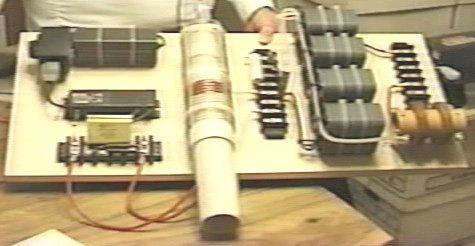 This device is not the easiest thing in the world to understand. Here is the circuit diagram:  it is probably worth mentioning some of the main points which Don Smith appears to be making. There are some very important points being made here, and grasping these may make a considerable difference to our ability to tap into the excess energy available in our local environment. There are four points worth mentioning: 1. Voltage 2. Frequency 3. Magnetic / Electric relationship 4. Resonance 1. Voltage. We tend to view things with an 'intuitive' view, generally based on fairly simple concepts. For example, we automatically think that it is more difficult to pick up a heavy object than to pick up a light one. How much more difficult? Well, if it is twice as heavy, it would probably be about twice as much effort to pick it up. This view has developed from our experience of things which we have done in the past, rather than on any mathematical calculation or formula. Well, how about pulsing an electronic system with a voltage? How would the output power of a system be affected by increasing the voltage? Our initial 'off-the cuff' reaction might be that the power output might be increased a bit, but then hold on… we've just remembered that Watts = Volts x Amps, so if you double the voltage, then you would double the power in watts. So we might settle for the notion that if we doubled the voltage then we could double the output power. If we thought that, then we would be wrong. Don Smith points out that as capacitors and coils store energy, if they are involved in the circuit, then the output power is proportional to the square of the voltage used. Double the voltage, and the output power is four times greater. Use three times the voltage and the output power is nine times greater. Use ten times the voltage and the output power is one hundred times greater !  Don says that the energy stored, multiplied by the cycles per second, is the energy being pumped by the system. Capacitors and inductors (coils) temporarily store electrons, and their performance is given by: Capacitor formula: W = 0.5 x C x V2 x Hz where: W is the energy in Joules (Joules = Volts x Amps x seconds) C is the capacitance in Farads V is the voltage Hz is the cycles per second Inductor formula: W = 0.5 x L x A2 x Hz where: W is the energy in Joules L is the inductance in henrys A is the current in amps Hz is the frequency in cycles per second You will notice that where inductors (coils) are involved, then the output power goes up with the square of the current. Double the voltage and double the current gives four times the power output due to the increased voltage and that increased output is increased by a further four times due to the increased current, giving sixteen times the output power. 2. Frequency. You will notice from the formulas above, that the output power is directly proportional to the frequency "Hz". The frequency is the number of cycles per second (or pulses per second) applied to the circuit. This is something which is not intuitive for most people. If you double the rate of pulsing, then you double the power output. When this sinks in, you suddenly see why Nikola Tesla tended to use millions of volts and millions of pulses per second. However, Don Smith states that when a circuit is at it's point of resonance, resistance in the circuit drops to zero and the circuit becomes effectively, a superconductor. The energy for such a system which is in resonance is: Resonant circuit: W = 0.5 x C x V2 x (Hz)2 where: W is the energy in Joules C is the capacitance in Farads V is the voltage Hz is the cycles per second If this is correct, then raising the frequency in a resonating circuit has a massive effect on the power output of the device. The question then arises: why is the mains power in Europe just fifty cycles per second and in America just sixty cycles per second? If power goes up with frequency, then why not feed households at a million cycles per second? One major reason is that it is not easy to make electric motors which can be driven with power delivered at that frequency, so a more suitable frequency is chosen in order to suit the motors in vacuum cleaners, washing machines and other household equipment. However, if we want to extract energy from the environment, then we should go for high voltage and high frequency. Then, when high power has been extracted, if we want a low frequency suited to electric motors, we can pulse the already captured power at that low frequency. It might be speculated that if a device is being driven with sharp pulses which have a very sharply rising leading edge, that the effective frequency of the pulsing is actually determined by the speed of that rising edge, rather than the rate at which the pulses are actually generated. For example, if pulses are being generated at, say, 50 kHz but the pulses have a leading edge which would be suited to a 200 kHz pulse train, then the device might well see the signal as a 200 kHz signal with a 25% Mark/Space ratio, the very suddenness of the applied voltage having a magnetic shocking effect equivalent to a 200 kHz pulse train. 3. Magnetic / Electric relationship. Don states that the reason why our present power systems are so inefficient is because we concentrate on the electric component of electromagnetism. These systems are always COP<1 as electricity is the 'losses' of electromagnetic power. Instead, if you concentrate on the magnetic component, then there is no limit on the electric power which can be extracted from that magnetic component. Contrary to what you might expect, if you install a pick-up system which extracts electrical energy from the magnetic component, you can install any number of other identical pick-ups, each of which extract the same amount of electrical energy from the magnetic input, without loading the magnetic wave in any way. Unlimited electrical output for the 'cost' of creating a single magnetic effect. The magnetic effect which we want to create is a ripple in the zero-point energy field, and ideally, we want to create that effect while using very little power. Creating a dipole with a battery which has a Plus and a Minus terminal or a magnet which has North and South poles, is an easy way to do create an electromagnetic imbalance in the local environment. Pulsing a coil is probably an even better way as the magnetic field reverses rapidly if it is an air-core coil, such as a Tesla Coil. Using a ferromagnetic core to the coil can create a problem as iron can't reverse it's magnetic alignment very rapidly, and ideally, you want pulsing which is at least a thousand times faster than iron can handle. 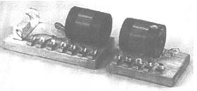 Don draws attention to the "Transmitter / Receiver" educational kit "Resonant Circuits #10-416" which was supplied by The Science Source, Maine. This kit demonstrated the generation of resonant energy and it's collection with a receiver circuit. However, if several receiver circuits are used, then the energy collected is increased several times without any increase in the transmitted energy. This is similar to a radio transmitter where hundreds of thousands of radio receivers can receive the transmitted signal without loading the transmitter in any way. In Don’s day, this kit was driven by a 1.5 volt battery and lit a 60-watt bulb which was supplied. Not surprisingly, that kit has been discontinued and a trivial kit substituted. If you get the Science Source educational kit, then there are some details which you need to watch out for. The unit has two very nice quality plastic bases and two very neatly wound coils each of 60 turns of 0.47 mm diameter enamelled copper wire on clear acrylic tubes 57 mm (2.25”) in diameter. The winding covers a 28 mm section of the tube. The layout of the transmitter and receiver modules does not match the accompanying instruction sheet and so considerable care needs to be taken when wiring up any of their circuits. The circuit diagrams are not shown, just a wiring diagram, which is not great from an educational point of view. The one relevant circuit is:  Before you buy the kit, it is not mentioned that in order to use it, you now need a signal generator capable of producing a 10-volt signal at 1 MHz. The coil has a DC resistance of just 1.9 ohms but at a 1 MHz resonant frequency, the necessary drive power is quite low. A variable capacitor is mounted on the receiver coil tube, but the one in my kit made absolutely no difference to the frequency tuning, nor was my capacitance meter able to determine any capacitance value for it at all, even though it had no trouble at all in measuring the 101 pF capacitor which was exactly the capacitance printed on it. For that reason, it is shown in blue in the circuit diagram above. Disconnecting it made no difference whatsoever. In this particular kit, standard screw connectors have had one screw replaced with an Allen key headed bolt which has a head large enough to allow finger tightening. Unfortunately, those bolts have a square cut tip where a domed tip is essential if small diameter wires are to be clamped securely. If you get the kit, then I suggest that you replace the connectors with a standard electrical screw connector strip. In tests, the LED lights up when the coils are aligned and within about 100 mm of each other, or if they are close together side by side. This immediately makes the Hubbard device spring to mind. Hubbard has a central "electromagnetic transmitter" surrounded by a ring of "receivers" closely coupled magnetically to the transmitter, each of which will receive a copy of the energy sent by the transmitter:  Don points to an even more clearly demonstrated occurrence of this effect in the Tesla Coil. In a typical Tesla Coil, the primary coil is much larger diameter than the inner secondary coil:  If, for example, 8,000 volts is applied to the primary coil which has four turns, then each turn would have 2,000 volts of potential. Each turn of the primary coil transfers electromagnetic flux to every single turn of the secondary winding, and the secondary coil has a very large number of turns. Massively more power is produced in the secondary coil than was used to energise the primary coil. A common mistake is to believe that a Tesla Coil can't produce serious amperage. If the primary coil is positioned in the middle of the secondary coil as shown, then the amperage generated will be as large as the voltage generated. A low power input to the primary coil can produce kilowatts of usable electrical power. 4. Resonance. An important factor in circuits aimed at tapping external energy is resonance. It can be hard to see where this comes in when it is an electronic circuit which is being considered. However, everything has it's own resonant frequency, whether it is a coil or any other electronic component. When components are connected together to form a circuit, the circuit has an overall resonant frequency. As a simple example, consider a swing:  If the swing is pushed before it reaches the highest point on the mother's side, then the push actually opposes the swinging action. The time of one full swing is the resonant frequency of the swing, and that is determined by the length of the supporting ropes holding the seat and not the weight of the child nor the power with which the child is pushed. Provided that the timing is exactly right, a very small push can get a swing moving in a substantial arc. The key factor is, matching the pulses applied to the swing, that is, to the resonant frequency of the swing. Get it right and a large movement is produced. Get it wrong, and the swing doesn't get going at all (at which point, critics would say "see, see …swings just don't work - this proves it !!"). This principle is demonstrated in the video here. Establishing the exact pulsing rate needed for a resonant circuit is not particularly easy, because the circuit contains coils (which have inductance, capacitance and resistance), capacitors (which have capacitance and a small amount of resistance) and resistors and wires, both of which have resistance and some capacitance. These kinds of circuit are called "LRC" circuits because "L" is the symbol used for inductance, "R" is the symbol used for resistance and "C" is the symbol used for capacitance. Don Smith provides instructions for winding and using the type of air-core coils needed for a Tesla Coil. He says: 1. Decide a frequency and bear in mind, the economy of the size of construction selected. The factors are: (a) Use radio frequency (above 20 kHz). (b) Use natural frequency, i.e. match the coil wire length to the frequency - coils have both capacitance and inductance. (c) Make the wire length either one quarter, one half of the full wavelength. (d) Calculate the wire length in feet as follows: If using one quarter wavelength, then divide 247 by the frequency in MHz. If using one half wavelength, then divide 494 by the frequency in MHz. If using the full wavelength, then divide 998 by the frequency in MHz. For wire lengths in metres: If using one quarter wavelength, then divide 75.29 by the frequency in MHz. If using one half wavelength, then divide 150.57 by the frequency in MHz. If using the full wavelength, then divide 304.19 by the frequency in MHz. 2. Choose the number of turns to be used in the coil when winding it using the wire length just calculated. The number of turns will be governed by the diameter of the tube on which the coil is to be wound. Remember that the ratio of the number of turns in the "L - 1" and "L - 2" coils, controls the overall output voltage. For example, if the voltage applied the large outer coil "L - 1" is 2,400 volts and L - 1 has ten turns, then each turn of L - 1 will have 240 volts dropped across it. This 240 volts of magnetic induction transfers 240 volts of electricity to every turn of wire in the inner "L - 2" coil. If the diameter of L - 2 is small enough to have 100 turns, then the voltage produced will be 24,000 volts. If the diameter of the L - 2 former allows 500 turns, then the output voltage will be 120,000 volts. 3. Choose the length and diameter of the coils. The larger the diameter of the coil, the fewer turns can be made with the wire length and so the coil length will be less, and the output voltage will be lower. 4. For example, if 24.7 MHz is the desired output frequency, then the length of wire, in feet, would be 247 divided by 24.7 which is 10 feet of wire (3,048 mm). The coil may be wound on a standard size of PVC pipe or alternatively, it can be purchased from a supplier - typically, an amateur radio supply store. If the voltage on each turn of L - 1 is arranged to be 24 volts and the desired output voltage 640 volts, then there needs to be 640 / 24 = 26.66 turns on L - 2, wound with the 10 feet of wire already calculated. PJK: At this point, Don's calculations go adrift and he suggests winding 30 turns on a 2-inch former. If you do that, then it will take about 16 feet of wire and the resonant point at 10-feet will be at about 19 turns, giving an output voltage of 458 volts instead of the required 640 volts, unless the number of turns on L1 is reduced to give more than 24 volts per turn. However, the actual required diameter of the coil former (plus one diameter of the wire) is 10 x 12 / (26.67 x 3.14159) = 1.43 inches. You can make this size of former up quite easily if you want to stay with ten turns on the L1 coil. 5. Connect to the start of the coil. To determine the exact resonant point on the coil, a measurement is made. Off-the-shelf multimeters are not responsive to high-frequency signals so a cheap neon is used instead. Holding one wire of the neon in one hand and running the other neon wire along the outside of the L - 2 winding, the point of brightest light is located. Then the neon is moved along that turn to find the brightest point along that turn, and when it is located, a connection is made to the winding at that exact point. L - 2 is now a resonant winding. It is possible to increase the ("Q") effectiveness of the coil by spreading the turns out a bit instead of positioning them so that each turn touches both of the adjacent turns. 6. The input power has been suggested as 2,400 volts. This can be constructed from a Jacob's ladder arrangement or any step-up voltage system. An off-the-shelf module as used with lasers is another option. 7. Construction of the L - 1 input coil has been suggested as having 10 turns. The length of the wire in this coil is not critical. If a 2-inch diameter PVC pipe was used for the L - 2 coil, then the next larger size of PVC pipe can be used for the L - 1 coil former. Cut a 10-turn length of the pipe (probably a 3-inch diameter pipe). The pipe length will depend on the diameter of the insulated wire used to make the winding. Use a good quality multimeter or a specialised LCR meter to measure the capacitance (in Farads) and the inductance (in henrys) of the L - 2 coil. Now, put a capacitor for matching L - 1 to L - 2 across the voltage input of L - 1, and a spark gap connected in parallel is required for the return voltage from L - 1. A trimmer capacitor for L - 1 is desirable. 8. The performance of L - 2 can be further enhanced by attaching an earth connection to the base of the coil. The maximum output voltage will be between the ends of coil L - 2 and lesser voltages can be taken off intermediate points along the coil if that is desirable. This frequency information can be rather hard to understand in the way that Don states it. It may be easier to follow the description given by one developer who says: I have noticed that any machine can be made a super machine just by adding a bipolar capacitor across the coil. Nothing else is needed. With the correct capacitor the coil becomes Naturally Resonant and uses very little Amperage. Each machine uses a different size capacitor. The correct capacitor size can be calculated by dividing the speed of light by the coil's wire length first to get the coil's Natural Frequency and then dividing the voltage to be used by that frequency. The result is the correct size for the capacitor. Your machine will then be very powerful even working from a 12V car battery, no other additions needed. My coil's wire length is 497.333 meters. 299000000 m/sec / 497.333 m = 600000 Hz. 12V / 600000 = 0.00002 or 20 microfarads. A beautiful Naturally Resonant Tank circuit. You can use this with any coil for overunity! Once we have a Naturally Resonant Coil/Capacitor combination we can bring the frequency down to 50 Hz by calculating for the Power Factor Correction: Hz = Resistance x Farads then 50 Hz = R x 0.00002 so 50 / 0.00002 = 2500000 and R = 2500000 or 2.5 Meg Ohms. We then place all three components in parallel and our coil should give us a 50 Hz output. Don provides quite an amount of information on one of his devices shown here: Without his description of the device, it would be difficult to understand it's construction and method of operation. As I understand it, the circuit of what is mounted on this board is as shown here:  This arrangement has bothered some readers recently as they feel that the spark gap should be in series with the L1 coil, like this:  This is understandable, as there is always a tendency to think of the spark gap as being a device which is there to protect against excessive voltages rather than seeing it as an active component of the circuit, a component which is in continuous use. In 1925, Hermann Plauson was granted a patent for a whole series of methods for converting the high voltage produced by a tall aerial system into useable, standard electricity. Hermann starts off by explaining how high voltage can be converted into a convenient form and he uses a Wimshurst static electricity generator as an example of a constant source of high voltage. The output from a rectified Tesla Coil, a Wimshurst machine and a tall aerial are very much alike, and so Hermann's comments are very relevant here. He shows it like this:  Here, the output of the Wimshurst machine is stored in two high-voltage capacitors (Leyden jars) causing a very high voltage to be created across those capacitors. When the voltage is high enough, a spark jumps across the spark gap, causing a massive surge of current through the primary winding of the transformer, which in his case is a step-down transformer as he is aimed at getting a lower output voltage. Don's circuit is almost identical:  Here the high voltage comes from the battery/inverter/neon-tube driver/rectifiers, rather than from a mechanically driven Wimshurst machine. He has the same build up of voltage in a capacitor with a spark gap across the capacitor. The spark gap will fire when the capacitor voltage reaches its designed level. The only difference is in the positioning of the capacitor, which if it matched Hermann's arrangement exactly, would be like this:  which would be a perfectly viable arrangement as far as I can see. You will remember that Tesla, who always speaks very highly of the energy released by the very sharp discharge produced by a spark, shows a high-voltage source feeding a capacitor with the energy passing through a spark gap to the primary winding of a transformer:  However, with Don's arrangement, it can be a little difficult to see why the capacitor is not short-circuited by the very low resistance of the few turns of thick wire forming the L1 coil. Well, it would do that if we were operating with DC, but we are most definitely not doing that as the output from the neon-tube driver circuit is pulsing 35,000 times per second. This causes the DC resistance of the L1 coil to be of almost no consequence and instead, the coil's "impedance" or "reactance" (effectively, it's AC resistance) is what counts. Actually, the capacitor and the L1 coil being connected across each other have a combined "reactance" or resistance to pulsing current at this frequency. This is where the nomograph diagram comes into play, and there is a much easier to understand version of it a few pages later on in this document. So, because of the high pulsing frequency, the L1 coil does not short-circuit the capacitor and if the pulsing frequency matches the resonant frequency of the L1 coil (or a harmonic of that frequency), then the L1 coil will actually have a very high resistance to current flow through it. This is how a crystal set radio receiver tunes in a particular radio station, broadcasting on it's own frequency. Anyway, coming back to Don's device shown in the photograph above, the electrical drive is from a 12-volt battery which is not seen in the photograph. Interestingly, Don remarks that if the length of the wires connecting the battery to the inverter are exactly one quarter of the wave length of the frequency of the oscillating magnetic field generated by the circuit, then the current induced in the battery wires will recharge the battery continuously, even if the battery is supplying power to the circuit at the same time. The battery supplies a small current through a protecting diode, to a standard off-the-shelf "true sine-wave" inverter. An inverter is a device which produces mains-voltage Alternating Current from a DC battery. As Don wants adjustable voltage, he feeds the output from the inverter into a variable transformer called a "Variac" although this is often made as part of the neon-driver circuit to allow the brightness of the neon tube to be adjusted by the user. This arrangement produces an AC output voltage which is adjustable from zero volts up to the full mains voltage (or a little higher, though Don does not want to use a higher voltage). The use of this kind of adjustment usually makes it essential for the inverter to be a true sine-wave type. As the power requirement of the neon-tube driver circuit is so low, the inverter should not cost very much. The neon-tube driver circuit is a standard off-the-shelf device used to drive neon tube displays for commercial establishments. The one used by Don contains an oscillator and a step-up transformer, which together produce an Alternating Current of 9,000 volts at a frequency of 35,100 Hz (sometimes written as 35.1 kHz). The term "Hz" stands for "cycles per second". Don lowers the 9,000 volts as he gets great power output at lower input voltages and the cost of the output capacitors is a significant factor. The particular neon-tube driver circuit which Don is using here, has two separate outputs out of phase with each other, so Don connects them together and uses a blocking diode in each line to prevent either of them affecting the other one. Not easily seen in the photograph, the high-voltage output line has a very small, encapsulated, Gas-Discharge Tube spark gap in it and the line is also earthed. The device looks like this:  Please note that when an earth connection is mentioned in connection with Don Smith's devices, we are talking about an actual wire connection to a metal object physically buried in the ground, whether it is a long copper rod driven into the ground, or an old car radiator buried in a hole like Tariel Kapanadze uses. When Thomas Henry Moray performed his requested demonstration deep in the countryside at a location chosen by the sceptics, the light bulbs which formed his demonstration electrical load, glowed more brightly with each hammer stroke as a length of gas pipe was hammered into the ground to form his earth connection. It should be remarked that since Don purchased his neon-tube driver module that newer designs have generally taken over completely, especially in Europe, and these designs have built in “earth-leakage current” protection which instantly disables the circuit if any current is detected leaking to ground. This feature makes the unit completely unsuitable for use in a Don Smith circuit because there, the transfer of current to the ground is wholly intentional and vital for the operation of the circuit. The output of the neon-tube driver circuit is used to drive the primary "L1" winding of a Tesla Coil style transformer. This looks ever so simple and straightforward, but there are some subtle details which need to be considered. The operating frequency of 35.1 kHz is set and maintained by the neon-tube driver circuitry, and so, in theory, we do not have to do any direct tuning ourselves. However, we want the resonant frequency of the L1 coil and the capacitor across it to match the neon-driver circuit frequency. The frequency of the "L1" coil winding will induce exactly the same frequency in the "L2" secondary winding. However, we need to pay special attention to the ratio of the wire lengths of the two coil windings as we want these two windings to resonate together. A rule of thumb followed by most Tesla Coil builders is to have the same weight of copper in the L1 and L2 coils, which means that the wire of the L1 coil is usually much thicker than the wire of the L2 coil. If the L1 coil is to be one quarter of the length of the L2 coil, then we would expect the cross-sectional area of the L1 coil to be four times that of the wire of the L2 coil and so the wire should have twice the diameter (as the area is proportional to the square of the radius, and the square of two is four). 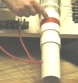 Don uses a white plastic tube as the former for his "L1" primary coil winding. As you can see here, the wire is fed into the former, leaving sufficient clearance to allow the former to slide all the way into the outer coil. The wire is fed up inside the pipe and out through another hole to allow the coil turns to be made on the outside of the pipe. There appear to be five turns, but Don does not always go for a complete number of turns, so it might be 4.3 turns or some other value. The key point here is that the length of wire in the "L1" coil turns should be exactly one quarter of the length of wire in the "L2" coil turns. The "L2" coil used here is a commercial 3-inch diameter unit from Barker & Williamson, constructed from uninsulated, solid, single-strand "tinned" copper wire (how to make home-build versions is shown later on). Don has taken this coil and unwound four turns in the middle of the coil in order to make a centre-tap. He then measured the exact length of wire in the remaining section and made the length of the "L1" coil turns to be exactly one quarter of that length. The wire used for the "L1" coil looks like Don's favourite "Jumbo Speaker Wire" which is a very flexible wire with a very large number of extremely fine uninsulated copper wires inside it. You will notice that Don has placed a plastic collar on each side of the winding, matching the thickness of the wire, in order to create a secure sliding operation inside the outer "L2" coil, and the additional plastic collars positioned further along the pipe provide further support for the inner coil. This sliding action allows the primary coil "L1" to be positioned at any point along the length of the "L2" secondary coil, and that has a marked tuning effect on the operation of the system. The outer "L2" coil does not have any kind of tube support but instead, the coil shape is maintained by the stiffness of the solid wire plus four slotted strips. This style of construction produces the highest possible coil performance at radio frequencies. With a Tesla Coil, it is most unusual to have the L1 coil of smaller diameter than the L2 coil. 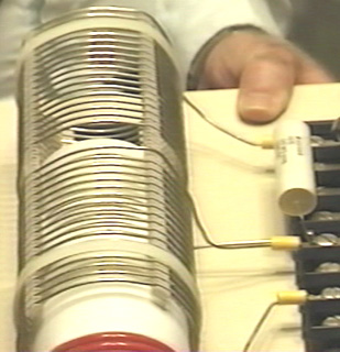 The "L2" coil has two separate sections, each of seventeen turns. One point to note is the turns are spaced apart using slotted strips to support the wires and maintain an accurate spacing between adjacent turns. It must be remembered that spacing coil turns apart like this alters the characteristics of the coil, increasing it's "capacitance" factor substantially. Every coil has resistance, inductance and capacitance, but the form of the coil construction has a major effect on the ratio of these three characteristics. The coil assembly is held in position on the base board by two off-white plastic cable ties. The nearer half of the coil is effectively connected across the further half as shown in the circuit diagram above. One point which Don stresses, is that the length of the wire in the "L1" coil and the length of wire in the "L2" coil, must be an exact even division or multiple of each other (in this case, the "L2" wire length in each half of the "L2" coil is exactly four times as long as the "L1" coil wire length). This is likely to cause the "L1" coil to have part of a turn, due to the different coil diameters. For example, if the length of the "L2" coil wire is 160 inches and "L1" is to be one quarter of that length, namely, 40 inches. Then, if the "L1" coil has an effective diameter of 2.25 inches, (allowing for the thickness of the wire when wound on a 2-inch diameter former), then the "L1" coil would have 5.65 (or 5 and 2/3) turns which causes the finishing turn of "L2" to be 240 degrees further around the coil former than the start of the first turn - that is, five full turns plus two thirds of the sixth turn. The L1 / L2 coil arrangement is a Tesla Coil. The positioning of the "L1" coil along the length of the "L2" coil, adjusts the voltage to current ratio produced by the coil. When the "L1" coil is near the middle of the "L2" coil, then the amplified voltage and amplified current are roughly the same. The exact wire ratio of these two coils gives them an almost automatic tuning with each other, and the exact resonance between them can be achieved by the positioning of the "L1" coil along the length of the "L2" coil. While this is a perfectly good way of adjusting the circuit, in the build shown in the photograph, Don has opted to get the exact tuning by connecting a capacitor across "L1" as marked as "C" in the circuit diagram. Don found that the appropriate capacitor value was around the 0.1 microfarad (100 nF) mark. It must be remembered that the voltage across "L1" is very high, so if a capacitor is used in that position it will need a voltage rating of at least 9,000 volts. Don remarks that the actual capacitors seen in the photograph of this prototype are rated at fifteen thousand volts, and were custom made for him using a "self-healing" style of construction. As has already been remarked, this capacitor is an optional component. Don also opted to connect a small capacitor across the "L2" coil, also for fine-tuning of the circuit, and that component is optional and so is not shown on the circuit diagram. As the two halves of the "L2" coil are effectively connected across each other, it is only necessary to have one fine-tuning capacitor. However, Don stresses that the "height" length of the coil (when standing vertically) controls the voltage produced while the coil "width" (the diameter of the turns) controls the current produced. 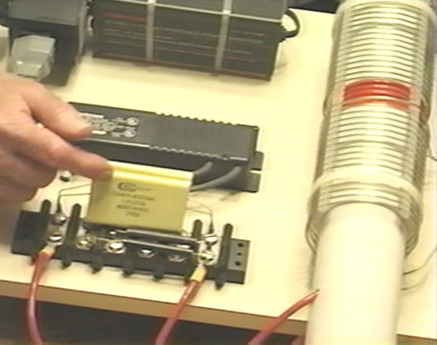 The exact wire length ratio of the turns in the "L1" and "L2" coils gives them an almost automatic synchronous tuning with each other, and the exact resonance between them can be achieved by the positioning of the "L1" coil along the length of the "L2" coil. While this is a perfectly good way of adjusting the circuit, in the 1994 build shown in the photograph, Don has opted to get the exact tuning by connecting a capacitor across "L1" as marked as "C" in the circuit diagram. Don found that the appropriate capacitor value for his particular coil build, was about 0.1 microfarad (100 nF) and so he connected two 47 nF high-voltage capacitors in parallel to get the value which he wanted. It must be remembered that the voltage across "L1" is very high, so a capacitor used in that position needs a voltage rating of at least 9,000 volts. Don remarks that the actual capacitors seen in the photograph of this prototype are rated at fifteen thousand volts, and were custom made for him using a "self-healing" style of construction. Don has also connected a small capacitor across the "L2" coil, and that optional component is marked as "C2" in the circuit diagram and the value used by Don happened to be a single 47nF, high-voltage capacitor. As the two halves of the "L2" coil are effectively connected across each other, it is only necessary to have one capacitor for "L2": 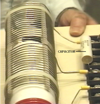 There are various ways of dealing with the output from the "L2" coil in order to get large amounts of conventional electrical power out of the device. The method shown here uses the four very large capacitors seen in the photograph. These have an 8,000 or 9,000 volt rating and a large capacity and they are used to store the circuit power as DC prior to use in the load equipment. This is achieved by feeding the capacitor bank through a diode which is rated for both high voltage and high current, as Don states that the device produces 8,000 volts at 20 amps, in which case, this rectifying diode has to be able to handle that level of power, both at start-up when the capacitor bank is fully discharged and "L2" is producing 8,000 volts, and when the full load of 20 amps is being drawn. This capacitor bank is fed through a diode which is rated for both high voltage and high current, as Don states that the device produces 8,000 volts at 20 amps, in which case, this rectifying diode has to be able to handle that level of power, both at start-up when the capacitor bank is fully discharged and "L2" is producing 8,000 volts, and when the full load of 20 amps is being drawn. The actual diodes used by Don happen to be rated at 25 KV but that is a far greater rating than is actually needed. In passing, it might be remarked that the average home user will not have an electrical requirement of anything remotely like as large as this, seeing that 10 kW is more than most people use on a continuous basis, while 8 KV at 20 A is a power of 160 kilowatts. As the neon-tube driver circuit can put out 9,000 volts and since the L1 / L2 coil system is a step-up transformer, if the voltage fed to the capacitor bank is to be kept down to 8,000 volts, then the Variac adjustment must be used to reduce the voltage fed to the neon-tube driver circuit, in order to lower the voltage fed to the L1 / L2 coil pair, typically, to 3,000 volts. A very astute and knowledgeable member of the EVGRAY Yahoo EVGRAY forum whose ID is "silverhealtheu" has recently pointed out that Don Smith says quite freely that he does not disclose all of the details of his designs, and it is his opinion that a major item which has not been disclosed is that the diodes in the circuit diagrams shown here are the wrong way round and that Don operates his voltages in reverse to the conventional way. In fact, the circuit diagram should be: He comments: "the diodes leaving the Neon-tube Driver may need to be reversed as we want to collect the negative polarity. The spark gap will then operate on ambient inversion and the spark will look and sound totally different with a much faster crack and producing very little heat and even becoming covered in frost is possible. The Variac should be raised up just enough to get a spark going then backed off slightly. Any higher voltage is liable to make the Neon-tube Driver think that it has a short-circuit condition, and the new electronic designs will then shut down automatically and fail to operate at all if this method is not followed. When running, C, L1 and L2 operate somewhere up in the Radio Frequency band because the Neon-tube Driver only acts as a tank-circuit exciter. The large collection capacitor C3, should fill inverted to earth polarity as shown above. The load will then be pulling electrons from the earth as the cap is REFILLED back to ZERO rather than the joules in the capacitor being depleted. Also remember that the Back-EMF systems of John Bedini and others, create a small positive pulse but they collect a super large NEGATIVE polarity spike which shoots off the bottom of an oscilloscope display. This is what we want, plenty of this stored in capacitors, and then let the ambient background energy supply the current when it makes the correction." This is a very important point and it may well make a really major difference to the performance of a device of this nature.  One reader has drawn attention to the fact that Don's main document indicates that there should be a resistor "R" across the L1 coil as well as the capacitor "C" and he suggests that the circuit should actually be as shown above, considering what Don said earlier about his "suitcase" design. Another reader points out that the wire in the output choke shown in the photograph below appears to be wound with wire that is far too small diameter to carry the currents mentioned by Don. It seems likely that a choke is not needed in that position except to suppress possible radio frequency transmissions from the circuit, but a more powerful choke can easily be wound using larger diameter wire. When the circuit is running, the storage capacitor bank behaves like an 8,000 volt battery which never runs down and which can supply 20 amps of current for as long as you want. The circuitry for producing a 220 volt 50 Hz AC output or a 110 volt 60 Hz AC output from the storage capacitors is just standard electronics. In passing, one option for charging the battery is to use the magnetic field caused by drawing mains-frequency current pulses through the output "choke" coil, shown here: 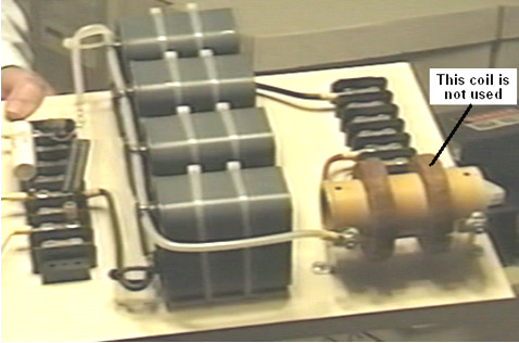 The output current flows through the left hand winding on the brown cylindrical former, and when the photograph was taken, the right-hand winding was no longer in use. Previously, it had been used to provide charging power to the battery by rectifying the electrical power in the coil, caused by the fluctuating magnetic field caused by the pulsing current flowing through the left hand winding, as shown here:  The DC output produced by the four diodes was then used to charge the driving battery, and the power level produced is substantially greater than the minor current drain from the battery. Consequently, it is a sensible precaution to pass this current to the battery via a circuit which prevents the battery voltage rising higher than it should. A simple voltage level sensor can be used to switch off the charging when the battery has reached its optimum level. Other batteries can also be charged if that is wanted. Simple circuitry of the type shown in chapter 12 can be used for controlling and limiting the charging process. The components on Don's board are laid out like this:  Don draws attention to the fact that the cables used to connect the output of "L2" to the output of the board, connecting the storage capacitors on the way, are very high-voltage rated cables with special multiple coverings to ensure that the cables will remain sound over an indefinite period. It should be remarked at this point, that the outer 3" diameter coil used by Don, is not wound on a former, but in order to get higher performance at high frequencies, the turns are supported with four separate strips physically attached to the turns - the technique described later in this document as being an excellent way for home construction of such coils. Please bear in mind that the voltages here and their associated power levels are literally lethal and perfectly capable of killing anyone who handles the device carelessly when it is powered up. When a replication of this device is ready for routine use, it must be encased so that none of the high-voltage connections can be touched by anyone. This is not a suggestion, but it is a mandatory requirement, despite the fact that the components shown in the photographs are laid out in what would be a most dangerous fashion were the circuit to be powered up as it stands. Under no circumstances, construct and test this circuit unless you are already experienced in the use of high-voltage circuits or can be supervised by somebody who is experienced in this field. This is a "one hand in the pocket at all times" type of circuit and it needs to be treated with great care and respect at all times, so be sensible. The remainder of the circuit is not mounted on the board, possibly because there are various ways in which the required end result can be achieved. The one suggested here is perhaps the most simple solution:  The voltage has to be dropped, so an iron-cored mains-frequency step-down transformer is used to do this. To get the frequency to the standard mains frequency for the country in which the device is to be used, an oscillator is used to generate that particular mains frequency. The oscillator output is used to drive a suitable high-voltage semiconductor device, be it an FET transistor, an IGBT device, or whatever. This device has to switch the working current at 8,000 volts, though admittedly, that will be a current which will be at least thirty six times lower than the final output current, due to the higher voltage on the primary winding of the transformer. The available power will be limited by the current handling capabilities of this output transformer which needs to be very large and expensive. As the circuit is capable of picking up additional magnetic pulses, such as those generated by other equipment, nearby lightning strikes, etc. an electronic component called a "varistor" marked "V" in the diagram, is connected across the load. This device acts as a voltage spike suppressor as it short circuits any voltage above its design voltage, protecting the load from power surges. Don also explains an even more simple version of the circuit as shown here:  This simplified circuit avoids the need for expensive capacitors and the constraints of their voltage ratings, and the need for electronic control of the output frequency. The wire length in the turns of coil "L2" still needs to be exactly four times the wire length of the turns in coil "L1", but there is only one component which needs to be introduced, and that is the resistor "R" placed across the primary winding of the step-down isolation transformer. This transformer is a laminated iron-core type, suitable for the low mains frequency, but the output from "L2" is at much higher frequency. It is possible to pull the frequency down to suit the step-down transformer by connecting the correct value of resistor "R" across the output transformer (or a coil and resistor, or a coil and a capacitor). The value of resistor needed can be predicted from the American Radio Relay League graph (shown as Fig.44 in Don's pdf document. The sixth edition of the Howard Sams book "Handbook of Electronics Tables and Formulas" (ISBN-10: 0672224690 or ISBN-13: 978-0672224690) has a table which goes down to 1 kHz and so does not need to be extended to reach the frequencies used here. The correct resistor value could also be found by experimentation. You will notice that an earthed dual spark gap has been placed across "L2" in order to make sure that the voltage levels always stay within the design range. Don also explains an even more simple version which does not need a Variac, high voltage capacitors or high voltage diodes. Here, a DC output is accepted which means that high-frequency step-down transformer operation can be used. This calls for an air-core transformer which you would wind yourself from heavy duty wire. Mains loads would then be powered by using a standard off-the-shelf inverter. In this version, it is of course, necessary to make the "L1" turns wire length exactly one quarter of the "L2" turns wire length in order to make the two coils resonate together. The operating frequency of each of these coils is imposed on them by the output frequency of the neon-tube driver circuit. That frequency is maintained throughout the entire circuit until it is rectified by the four diodes feeding the low-voltage storage capacitor. The target output voltage will be either just over 12 volts or just over 24 volts, depending on the voltage rating of the inverter which is to be driven by the system. The circuit diagram is:  As many people will find the nomograph chart in Don's pdf document very difficult to understand and use, here is an easier version:  The objective here is to determine the "reactance" or 'AC resistance' in ohms and the way to do that is as follows: Suppose that your neon-tube driver is running at 30 kHz and you are using a capacitor of 100 nF (which is the same as 0.1 microfarad) and you want to know what is the AC resistance of your capacitor is at that frequency. Also, what coil inductance would have that same AC resistance. Then the procedure for finding that out is as follows:  Draw a straight line from your 30 kHz frequency (purple line) through your 100 nanofarad capacitor value and carry the line on as far as the (blue) inductance line as shown above. You can now read the reactance ("AC resistance") off the red line, which looks like 51 ohms to me. This means that when the circuit is running at a frequency of 30 kHz, then the current flow through your 100 nF capacitor will be the same as through a 51 ohm resistor. Reading off the blue "Inductance" line that same current flow at that frequency would occur with a coil which has an inductance of 0.28 millihenries. I have been passed a copy of Don’s circuit diagram for this device, and it is shown here:  The 4000V 30mA transformer shown in this circuit diagram, may use a ferrite-cored transformer from a neon-tube driver module which steps up the voltage but it does not raise the frequency as that is clearly marked at 120 Hz pulsed DC. You will notice that this circuit diagram is drawn with Plus shown below Minus (which is most unusual). Please note that when an earth connection is mentioned in connection with Don Smith's devices, we are talking about an actual wire connection to a metal object physically buried in the ground, whether it is a long copper rod driven into the ground, or an old car radiator buried in a hole like Tariel Kapanadze used, or a buried metal plate. When Thomas Henry Moray performed his requested demonstration deep in the countryside at a location chosen by the sceptics, the light bulbs which formed his demonstration electrical load, glowed more brightly with each hammer stroke as a length of gas pipe was hammered into the ground to form his earth connection. Don also explains an even more simple version of his main device. This version does not need a Variac (variable voltage transformer) or high voltage capacitors. Here, a DC output is accepted which means that high-frequency step-down transformer operation can be used. This calls on the output side, for an air-core (or ferrite rod core) transformer which you would wind yourself from heavy duty wire. Mains loads would then be powered by using a standard off-the-shelf inverter. In this version, it is of course, very helpful to make the "L1" turns wire length exactly one quarter of the "L2" turns wire length in order to make the two coils automatically resonate together. The operating frequency of each of these coils is imposed on them by the output frequency of the neon-tube driver circuit. That frequency is maintained throughout the entire circuit until it is rectified by the four diodes feeding the low-voltage storage capacitor. The target output voltage will be either just over 12 volts or just over 24 volts, depending on the voltage rating of the inverter which is to be driven by the system. As the circuit is capable of picking up additional magnetic pulses, such as those generated by other equipment, nearby lightning strikes, etc. an electronic component called a "varistor" marked "V" in the diagram, is connected across the load. This device acts as a voltage spike suppressor as it short-circuits any voltage above its design voltage, protecting the load from power surges. A Gas-Discharge Tube is an effective alternative to a varistor. This circuit is effectively two Tesla Coils back-to-back and the circuit diagram might be:  It is by no means certain that in this circuit, the red and blue windings are wound in opposing directions. The spark gap (or gas-discharge tube) in series with the primary of the first transformer alters the operation in a somewhat unpredictable way as it causes the primary to oscillate at a frequency determined by it’s inductance and it’s self-capacitance, and that may result in megahertz frequencies. The secondary winding(s) of that transformer must resonate with the primary and in this circuit which has no frequency-compensating capacitors, that resonance is being produced by the exact wire length in the turns of the secondary. This looks like a simple circuit, but it is anything but that. The excess energy is produced by the raised frequency, the raised voltage, and the very sharp pulsing produced by the spark. That part is straightforward. The remainder of the circuit is likely to be very difficult to get resonating as it needs to be in order to deliver that excess energy to the output inverter. When considering the “length” of wire in a resonant coil, it is necessary to pay attention to the standing wave created under those conditions. The wave is caused by reflection of the signal when it reaches the end of the wire OR when there is a sudden change in the diameter of the wire as that changes the signal reflection ability at that point in the connection. You should pay attention to Richard Quick’s very clear description of this in the section of his patent which is included later on in this chapter. Also, remember what Don Smith said about locating the peaks of the standing wave by using a hand-held neon lamp. One very significant thing which Don pointed out is that the mains electricity available through the wall socket in my home, does not come along the wires from the generating station. Instead, the power station influences a local ‘sub-station’ and the electrons which flow through my equipment actually come from my local environment because of the influence of my local sub-station. Therefore, if I can create a similar influence in my home, then I no longer need that sub-station and can have as much electrical energy as I want, without having to pay somebody else to provide that influence for me. A Practical Implementation of one of Don Smith’s Designs The objective here, is to determine how to construct a self-powered, free-energy electrical generator which has no moving parts, is not too expensive to build, uses readily available parts and which has an output of some kilowatts. However, under no circumstances should this document be considered to be an encouragement for you, or anyone else to actually build one of these devices. This document is presented solely for information and educational purposes, and as high voltages are involved, it should be considered to be a dangerous device unsuited to being built by inexperienced amateurs. The following section is just my opinions and so should not be taken as tried and tested, working technology, but instead, just the opinion of an inexperienced writer. However, questions from several different readers indicate that a short, reasonably specific description of the steps needed to attempt a replication of a Don Smith device would be helpful. Again, this document must not be considered to be a recommendation that you actually build one of these high-voltage, potentially dangerous devices. This is just information intended to help you understand what I believe is involved in this process. In broad outline, the following steps are used in the most simple version of the arrangement: 1. The very low frequency and voltage of the local mains supply is discarded in favour of an electrical supply which operates at more than 20,000 Hz (cycles per second) and has a voltage of anything from 350 volts to 10,000 volts. The higher voltages can give greater overall output power, but they involve greater effort in getting the voltage back down again to the level of the local mains voltage in order for standard mains equipment to be used. 2. This high-frequency high voltage is used to create a series of very rapid sparks using a spark gap which is connected to a ground connection. Properly done, the spark frequency is so high that there is no audible sound caused by the sparks. Each spark causes a flow of energy from the local environment into the circuit. This energy is not standard electricity which makes things hot when current flows through them, but instead this energy flow causes things to become cold when the power flows through them, and so it is often called “cold” electricity. It is tricky to use this energy unless all you want to do is light up a series of light bulbs (which incidentally, give out a different quality of light when powered with this energy). Surprisingly, the circuit now contains substantially more power than the amount of power needed to produce the sparks. This is because additional energy flows in from the ground as well as from the local environment. If you have conventional training and have been fed the myth of “closed systems”, then this will seem impossible to you. So, let me ask you the question: if, as can be shown, all of the electricity flowing into the primary winding of a transformer, flows back out of that winding, then where does the massive, continuous flow of electricity coming from the secondary winding come from? None of it comes from the primary circuit and yet millions of electrons flow out of the secondary in a continuous stream which can be supplied indefinitely. So, where do these electrons come from? The answer is ‘from the surrounding local environment which is seething with excess energy’ but your textbooks won’t like that fact as they believe that the transformer circuit is a ‘closed system’ – something which probably can’t be found anywhere in this universe. 3. This high-voltage, high-frequency, high-power energy needs to be converted to the same sort of hot electricity which comes out of a mains wall socket at the local voltage and frequency. This is where skill and understanding come into play. The first step is to lower the voltage and increase the available current with a step-down resonant transformer. This sounds highly technical and complicated, and looking at Don Smith’s expensive Barker & Williamson coil, makes the whole operation appear to be one for rich experimenters only. This is not the case and a working solution can be cheap and easy. It is generally not convenient to get the very high voltage all the way down to convenient levels in a single step, and so, one or more of those resonant transformers can be used to reach the target voltage level. Each step down transformer boosts the available current higher and higher. 4. When a satisfactory voltage has been reached, we need to deal with the very high frequency. The easiest way to deal with it is to use high-speed diodes to convert it to pulsing DC and feed that into a capacitor to create what is essentially, an everlasting battery. Feeding this energy into a capacitor converts it into conventional “hot” electricity and a standard off-the-shelf inverter can be used to give the exact voltage and frequency of the local mains supply. In most of the world, that is 220 volts at 50 cycles per second. In America it is 110 volts at 60 cycles per second. Low-cost inverters generally run on either 12 volts or 24 volts with the more common 12 volt units being cheaper. So, let’s take a look at each of these step in more detail and see if we can understand what is involved and what our options are: 1. We want to produce a high-voltage, high-frequency, low-current power source. Don Smith shows a Neon-Sign Transformer module. His module produced a voltage which was higher than was convenient and so he used a variable AC transformer or “Variac” as it is commonly known, to lower the input voltage and so, lower the output voltage. There is actually no need for a Variac as we can handle the higher voltage or alternatively, use a more suitable Neon-Sign Transformer module. However, we have a problem with using that technique. In the years since Don bought his module, they have been redesigned to include circuitry which disables the module if any current flows out of it directly to earth, and as that is exactly what we would want to use it for, so most, if not all of the currently available neon-sign transformer modules are not suitable for our needs. However, I’m told that if the module has an earth wire and that earth wire is left unconnected, that it disables the earth-leakage circuitry, allowing the unit to be used in a Don Smith circuit. Personally, I would not recommend that if the module is enclosed in a metal housing. A much cheaper alternative is shown here where a small plasma globe circuit is used to generate a high-frequency spark. It seems highly likely that one of those modules would suit our needs:  An alternative method is to build your own power supply from scratch. Doing that is not particularly difficult and if you do not understand any electronics, then perhaps, reading the beginner’s electronics tutorial here will fill you in on all of the basics needed for understanding (and probably designing your own) circuits of this type. Here is a variable frequency design for home-construction:  One advantage of this circuit is that the output transformer is driven at the frequency set by the 555 timer and that frequency is not affected by the number of turns in the primary winding, nor it’s inductance, wire diameter, or anything else to do with the coil. While this circuit shows the rather expensive IRF9130 transistor, I expect that other P-channel FETs would work satisfactorily in this circuit. The IRF9130 transistor looks like this:  The circuit has a power supply diode and capacitor, ready to receive energy from the output at some later date if that is possible and desired. The 555 circuit is standard, giving a 50% Mark/Space ratio. The 10 nF capacitor is there to maintain the stability of the 555 and the timing section consists of two variable resistors, one fixed resistor and the 1 nF capacitor. This resistor arrangement gives a variable resistance of anything from 100 ohms to 51.8K and that allows a substantial frequency range. The 47K (Linear) variable resistor controls the main tuning and the 4.7K (Linear) variable resistor gives a more easily adjustable frequency for exact tuning. The 100 ohm resistor is there in case both of the variable resistors are set to zero resistance. The output is fed through a 470 ohm resistor to the gate of a very powerful P-channel FET transistor which drives the primary winding of the output transformer. The output transformer can be wound on an insulating spool covering a ferrite rod, giving both good coupling between the windings, and high-frequency operation as well. The turns ratio is set to just 30:1 due to the high number of primary winding turns. With a 12-volt supply, this will give a 360-volt output waveform, and by reducing the primary turns progressively, allows the output voltage to be increased in controlled steps. With 10 turns in the primary, the output voltage should be 3,600 volts and with just 5 turns 7,200 volts. The higher the voltage used, the greater the amount of work needed later on to get the voltage back down to the output level which we want. Looking at the wire specification table, indicates that quite a small wire diameter could be used for the oscillator output transformer’s secondary winding. While this is perfectly true, it is not the whole story. Neon Tube Drivers are very small and the wire in their output windings is very small diameter indeed. Those driver modules are very prone to failure. If the insulation on any one turn of the winding fails and one turn becomes a short-circuit, then that stops the winding from oscillating, and a replacement is needed. As there are no particular size constraints for this project, it might be a good idea to use enamelled copper wire of 0.45 mm or larger in an attempt to avoid this insulation failure hazard. No part of the transformer coil spool should be metal and it would not be any harm to cover each layer of secondary winding with a layer of electrical tape to provide additional insulation between the coil turns in one layer and the turns in the layer on top of it. A plug-in board layout might be:  Please remember that you can’t just stick your average voltmeter across a 4 kV capacitor (unless you really do want to buy another meter) as they only measure up to about a thousand volts DC. So, if you are using high voltage, then you need to use a resistor-divider pair and measure the voltage on the lower resistor. But what resistor values should you use? If you put a 10 Megohm resistor across your 4 kV charged capacitor, the current flowing through the resistor would be 0.4 milliamps. Sounds tiny, doesn’t it? But that 0.4 mA is 1.6 watts which is a good deal more than the wattage which your resistor can handle. Even using this arrangement:  the current will be 0.08 mA and the wattage per resistor will be 64 mW. The meter reading will be about 20% of the capacitor voltage which will give a voltmeter reading of 800 volts. The input resistance of the meter needs to be checked and possibly, allowed for as the resistance in this circuit is so high (see chapter 12). When making a measurement of this type, the capacitor is discharged, the resistor chain and meter attached, and then, and only then, is the circuit powered up, the reading taken, the input power disconnected, the capacitor discharged, and the resistors disconnected. High-voltage circuits are highly dangerous, especially so, where a capacitor is involved. The recommendation to wear thick rubber gloves for this kind of work, is not intended to be humorous. Circuits of this type are liable to generate unexpected high-voltage spikes, and so, it might be a good idea to connect a varistor across the meter to protect it from those spikes. The varistor need to be set to the voltage which you intend to measure and as varistors may not be available above a 300V threshold, two or more may need to be connected in series where just one is shown in the diagram above. The varistor should not have a higher voltage rating than your meter. 2. We now need to use this high voltage to create a strategically positioned spark to a ground connection. When making an earth connection, it is sometimes suggested that connecting to water pipes or radiators is a good idea as they have long lengths of metal piping running under the ground and making excellent contact with it. However, it has become very common for metal piping to be replaced with cheaper plastic piping and so any proposed pipe connection needs a check to ensure that that there is metal piping which runs all the way into the ground.  The spark gaps shown can be commercial high-voltage gas discharge tubes, adjustable home-made spark gaps with stainless steel tips about 1 mm apart, car spark plugs, or standard neon bulbs, although these run rather hot in this application. A 15 mm x 6 mm size neon bulb operates with only 90 or 100 volts across it, it would take a considerable number of them connected in series to create a high voltage spark gap, but it is probably a misconception that the spark gap itself needs a high voltage. Later on in this chapter, there is an example of a very successful system where just one neon bulb is used for the spark gap and an oscillating magnetic field more than a meter wide is created when driven by just an old 2,500 volt neon-sign transformer module. If using a neon bulb for the spark gap, then an experienced developer recommends that a 22K resistor is used in series with the neon in order to extend it’s working life very considerably. This circuit is one way to connect the spark gap and ground connection:  This is an adaption of a circuit arrangement used by the forum member “SLOW-‘N-EASY” on the Don Smith topic in the energeticforum. Here, he is using a ‘LowGlow’ neon transformer intended for use on a bicycle. The diodes are there to protect the high-voltage power supply from any unexpected voltage spikes created later on in the circuit. The spark gap is connected between the primary winding of a step-up transformer and the earth connection. No capacitor is used. Seeing this circuit, we immediately think of Don Smith’s large and expensive coils, but this experimenter does not use anything like that. Instead, he winds his transformer on a simple plastic former like this:  And to make matters ‘worse’ the primary winding wire is just 9 inches (228.6 mm) long and the secondary just 36 inches (914.4 mm) long, the primary being wound directly on top of the secondary. Not exactly a large or expensive construction and yet one which appears to perform adequately in actual tests. This is a very compact form of construction, but there is no necessity to use exactly the same former for coils, nor is there anything magic about the nine-inch length of the L1 coil, as it could easily be any convenient length, say two feet or 0.5 metres, or whatever. The important thing is to make the L2 wire length exactly four times that length, cutting the lengths accurately. It is common practice to match the weight of copper in each coil and so the shorter wire is usually twice the diameter of the longer wire. The circuit above, produces a cold electricity output of high voltage and high frequency. The voltage will not be the same as the neon transformer voltage, nor is the frequency the same either. The two coils resonate at their own natural frequency, unaltered by any capacitors. 3. The next step is to get the high voltage down to a more convenient level, perhaps, like this:  Here, an identical transformer, wound in exactly the same way, is used in reverse, to start the voltage lowering sequence. The wire length ratio is maintained to keep the transformer windings resonant with each other. Supposing we were to wind the L2 coil of this second transformer in a single straight winding and instead of winding just one L1 winding on top of it, two or more L1 identical windings were placed on top of it – what would happen?:  Now for a comment which will seem heretical to people steeped in the present day (inadequate) level of technology. The power flowing in these transformers is cold electricity which operates in an entirely different way to hot electricity. The coupling between these coils would be inductive if they were carrying hot electricity and in that case, any additional power take-off from additional L1 coils would have to be ‘paid’ for by additional current draw through the L2 coil. However, with the cold electricity which these coils are actually carrying, the coupling between the coils is magnetic and not inductive and that results in no increase in L2 current, no matter how many L1 coil take-offs there are. Any additional L1 coils will be powered for free. However, the position of the coils relative to each other has an effect on the tuning, so the L1 coil should be in the middle of the L2 coil, which means that any additional L1 coils are going to be slightly off the optimum tuning point. 4. Anyway, following through on just one L1 coil, there is likely to be at least one further step-down transformer needed and eventually, we need conversion to hot electricity:  Probably the easiest conversion is by feeding the energy into a capacitor and making it standard DC. The frequency is still very high, so high-speed diodes (such as the 75-nanosecond UF54008) are needed here although the voltage level is now low enough to be no problem. The DC output can be used to power an inverter so that standard mains equipment can be used. It is not necessary to use just one (expensive) large-capacity inverter to power all possible loads as it is cheaper to have several smaller inverters, each powering it’s own set of equipment. Most equipment will run satisfactorily on square-wave inverters and that includes a mains unit for powering the input oscillator circuit. PVC pipe is not a great material when using high-frequency high-voltage signals, and grey PVC pipe is a particularly poor coil former material. The much more expensive acrylic pipe is excellent, but if using PVC, then performance will be better if the PVC pipe is coated with an insulating lacquer (or table tennis balls dissolved in acetone as show on YouTube). However, there are some other factors which have not been mentioned. For example, if the L1 coil is wound directly on top of the L2 coil, it will have roughly the same diameter and so, the wire being four times longer, will have roughly four times as many turns, giving a step-up or step-down ratio of around 4:1. If, on the other hand, the coil diameters were different, the ratio would be different as the wire lengths are fixed relative to each other. If the L2 coil were half the diameter of the L1 coil, then the turns ratio would be about 8:1 and at one third diameter, 12:1 and at a quarter diameter 16:1 which means that a much greater effect could be had from the same wire length by reducing the L2 coil diameter. However, the magnetic effect produced by a coil is linked to the cross-sectional area of the coil and so a small diameter is not necessarily at great advantage. Also, the length of the L1 coil wire and number of turns in it, affect the DC resistance, and more importantly, the AC impedance which affects the amount of power needed to pulse the coil. It is also thought that having the same weight of copper in each winding gives an improved performance, but what is not often mentioned is the opinion that the greater the weight of copper, the greater the effect. You will recall that Joseph Newman (chapter 11) uses large amounts of copper wire to produce remarkable effects. So, while 9 inches and 36 inches of wire will work for L1 and L2, there may well be improved performance from longer lengths of wire and/or thicker wires. We should also not forget that Don Smith pointed out that voltage and current act (out of phase and) in opposite directions along the L2 coil, moving away from the L1 coil:  It has been suggested that a greater and more effective power output can be obtained by splitting the L2 coil underneath the L1 coil position, winding the second part of L2 in the opposite direction and grounding the junction of the two L2 windings. Don doesn’t consider it necessary to reverse the direction of winding. The result is an L2 winding which is twice as long as before and arranged like this:  Here, the additional high-voltage diodes allow the two out of phase windings to be connected across each other. You will notice that this arrangement calls for two separate earth connections, both of which need to be high-quality connections, something like a pipe or rod driven deeply into moist soil or alternatively, a metal plate or similar metal object of substantial surface area, buried deep in moist earth, and a thick copper wire or copper braid used to make the connection. These earthing points need to be fairly far apart, say, ten metres. A single earth connection can’t be used as that would effectively short-circuit across the L1/L2 transformer which you really do not want to do. With this arrangement, the outline circuit becomes:  The thick earth wiring is helpful because in order to avoid the earth wire being included in the resonant wire length, you need a sudden change in wire cross-section:  These are just some ideas which might be considered by some experienced developer who may be thinking of investigating Don Smith style circuitry. To give you some idea of the capacity of some commercially available wires when carrying hot electricity, this table may help:  It is recommended that the wire have a current carrying capacity of 20% more than the expected actual load, so that it does not get very hot when in use. The wire diameters do not include the insulation, although for solid enamelled copper wire, that can be ignored. There is a most impressive video and circuit shown here where a very simple arrangement produces an immediately successful performance for the front end of Don’s circuitry. The circuit appears to be:  Here, a simple Neon Sign Transformer module which has no earth connection, is used to produce a 2.5 kV voltage with a frequency of 25 kHz and a maximum output current capacity of 12 mA. There is no difficulty in constructing the equivalent to that power supply unit. The two outputs from the module are converted to DC by a chain of four 1N4007 diodes in series in each of the two outputs (each chain being inside a plastic tube for insulation). This output is fed through an optional 22K resistor via a neon lamp to a microwave oven capacitor which happens to be 874 nF with a voltage rating of 2,100 volts. You might feel that the voltage rating of the capacitor is too low for the output voltage of the neon sign module, but the neon has a striking voltage of just 90 volts and so the capacitor is not going to reach the output voltage of the power supply. The resistors are solely to extend the life of the neons as the gas inside the tube gets a considerable jolt in the first nanosecond after switch-on. It is unlikely that omitting those resistors would have any significant effect, but then, including them is a trivial matter. The second neon feeds the primary of the resonant transformer which is only shown in notional outline in the diagram above as the developer suggests that the primary acts as a transmitter and that any number of receiving coils can be used as individual secondaries by being tuned to the exact frequency of that resonating primary.  In the video showing this arrangement, the developer demonstrates the fluctuating, high-frequency field which extends for some four feet (1.2 m) around the coil. He also remarks that the single neons in his arrangement could each be replaced with two neons in series. In test which I ran, I found that I needed two neons in series ahead of the capacitor in order to get continuous lighting of the output neon. Also, one of the diodes needed to be reversed so that one faced towards the input and one away from it. It did not matter which diode was reversed as both configurations worked. Again, please note that this presentation is for information purposes only and it is NOT a recommendation that you should actually build one of these devices. Let me stress again that this is a high-voltage device made even more dangerous by the inclusion of a capacitor, and it is quite capable of killing you, so, don’t build one. The developer suggests that it is an implementation of the “transmitter” section of Don’s Transmitter/multiple-receivers design shown below. However, before looking at that design, there is one question which causes a good deal of discussion on the forums, namely, if the centre-tap of the L2 secondary coil is connected to ground, then should that earth-connection wire length be considered to be part of the quarter length of the L1 coil? To examine this possibility in depth, the following quote from Richard Quick’s very clear explanation of resonance in his US patent 7,973,296 of 5th July 2011 is very helpful. However, the simple answer is that for there to be exact resonance between two lengths of wire (whether or not part, or all of those lengths of wire happen to be wound into a coil), then one length needs to be exactly four times as long as the other, and ideally, half the diameter as well. At both ends of both lengths of wire, there needs to be a sudden change in wire diameter and Richard explains why this is. But, leaving that detailed explanation for now, we can use that knowledge to explain the above simplified system in more detail. Here is the circuit again:  One very important point to note is that no earth connection is required and in spite of that, the performance shown on video is very impressive. While an earth connection can feed substantial power into the circuit, not needing one for the front end is an enormous advantage and potentially, opens the way for a truly portable device. Another very important point is the utter simplicity of the arrangement where only cheap, readily available components are used (and not many of those are needed). The resistors for extending the life of the neon bulbs are not shown, but they can be included if desired and the circuit operation is not altered significantly by having them there. If a higher spark voltage is wanted, then two or more neon bulbs can be used in series where these circuit diagrams show just one. A point to note is that the lower diode is shown reversed when compared to the previous diagram. This is because the power supply shown is any generic power supply which drives a simple output coil which does not have a centre tap. The neon supply of the earlier diagram appears to have two separate outputs which will, presumably, be out of phase with each other as that is common practice for neon-sign driver modules. If you wish, the two diodes shown here could be replaced by a diode bridge of four high-voltage, high-speed diodes. The wire lengths of L1 and L2 are measured very accurately from where the wire diameter changes suddenly, as indicated by the red dashed lines. The L2 wire length is exactly four times as long as the L1 wire length and the L2 wire diameter is half of the L1 wire diameter. How long is the L1 wire? Well, how long would you like it to be? It can be whatever length you want and the radius of the L1 coil can be whatever you want it to be. The theory experts will say that the L1 coil should resonate at the frequency of the power feeding it. Well, good for them, I say, so please tell me what frequency that is. It is not going to be the frequency of the power supply as that will be changed by at least one of the neon bulbs. So, what frequency will the neon bulb produce? Not even the manufacturer could tell you that as there is quite a variation between individual bulbs which are supposedly identical. Actually, it doesn’t matter at all, because the L1 coil (and the L2 coil if you measure them accurately) has a resonant frequency all of its own and it will vibrate at that frequency no matter what the frequency feeding it happens to be. A coil resonates in very much the same way that a bell rings when it is struck. It doesn’t matter how hard you strike the bell or how rapidly you strike it – the bell will ring at it’s own natural frequency. So the L1 coil will resonate at it’s own natural frequency no matter what rate the voltage spikes striking it arrive, and as the L2 coil has been carefully constructed to have exactly that same frequency, it will resonate in synchronisation with the L1 coil. This means that the length of the wire for the L1 coil is the choice of the builder, but once that length is chosen it determines the length of the wire for the L2 coil as that is exactly four times as long, unless the builder decides to use an arrangement which has L2 wound in both the Clockwise and counter-clockwise directions, in which case, each half of the L2 coil will be four times the length of the wire in the L1 coil, like this:  Mind you, there is one other factor to be considered when deciding what the most convenient wire length for L1 might be, and that is the number of turns in the L1 coil. The larger the ratio between the turns in L1 and the turns in L2, the higher the voltage boost produced by the L1/L2 transformer, and remember that the length of L2 is fixed relative to the length of L1. So, a possible circuit style might be:  There are some important points to remember. One is that there must be a sudden change of wire diameter at both ends of each L1 coil and at the ends of each L2 coil. If there isn’t, then the connecting wire length will form part of the coil and if there is some change in diameter but not very much, then it is anybody’s guess what the resonant wire length for that coil will be. There can be as many step-down isolation air-core L1/L2 transformers as desired and these do not need to be particularly large or expensive. The builder of this circuit put it together in just a few minutes, using components which were to hand, including the microwave oven capacitor marked “C” in the diagrams above. That capacitor is isolated on both sides by the neon bulb spark gaps and so it will have no modifying effect on the resonant frequency of any of the coils in this circuit. But it is vital to understand that the energy stored in that capacitor can, and will, kill you instantly if you were to touch it, so let me stress once again that this information is NOT a recommendation that you actually build this circuit. The DC output from the circuit is intended to power a standard inverter, which in turn, would be perfectly capable of powering the high voltage, high frequency input oscillator. One final point is that as demonstrated in the video, the oscillating magnetic field produced by the L1 coil can power several identical L2 coils, giving several additional power outputs for no increase in input power, because the coupling is magnetic and not inductive as mentioned earlier in this chapter. Please notice that neither the L1 coil nor the L2 coil has a capacitor connected across it, so resonance is due solely to wire length and no expensive high-voltage capacitors are needed to get every L1/L2 coil pair resonating together. One possible arrangement might be like this:  Where two of the L2 coils are shown connected together to give increased output power. This arrangement uses low-voltage inexpensive components for the output stages and there is no obvious limit to the amount of output power which could be provided. As the circuit operates at high frequency throughout, there is no particular need for additional L2 coils to be placed physically inside the L1 coil:  However, there can be an advantage to this arrangement in that the wire length of the L1 coil is greater, which in turn makes the wire length of each L2 coil greater (being four times longer). This gives greater flexibility when planning the turns ratio of the L1/L2 transformer. The voltage step-up or step-down of that transformer happens to be in the ratio of the turns, in spite of the fact that this is not inductive coupling and so standard transformer technology does not apply. When you choose the number of turns and coil diameter for L1, that also gives the length of the L2 wire. In order to get the desired output voltage, if perhaps, the step-down ratio is needed to be an amount of 46:1, then you need 46 times the number of L1 turns on the L2 coil. That means that you know both the wire length and number of turns wanted in the L2 coil. But, as each turn will have a length of 3.14159 times the diameter, it follows then that the wanted diameter is the wire length per turn, divided by 3.14159. The wire sits on top of the tube on which it is wound and so has a greater diameter by one wire thickness, so the calculated tube diameter needs to be reduced by one wire diameter. For example, if the length per turn is 162 mm and the wire diameter 0.8 mm, then the tube diameter would be 162 / 3.14159 – 0.8 which is 50.766 mm (just over two inches). Now for Richard’s explanation of the resonant frequency of any length of wire: “Quarter-Wave” Resonance; Standing Electromagnetic Waves” One of the two main types is electrical resonance is referred to here as quarter-wave resonance. This type of resonance depends almost entirely on the length of a wire element For reasons described below, if a segment or length of wire is one quarter as long as the “voltage waves” which are travelling through the wire, then a set of “reflected” waves will be added to the emitted waves, in a synchronised alignment which creates stronger “superimposed waves”. Accordingly, an understanding of the “quarter-wave” phenomenon will help a reader understand how a straightforward and easily-controlled factor (i.e., the length of a wire ribbon which will be used to form a spiral coil) can help create a “quarter-wave” resonant response, which will create the types of electromagnetic pulses and fields referred to as “standing waves”. The speed at which a voltage impulse is transmitted through a metal wire is extremely fast. It is essentially the same as the speed of light, which travels 300 million meters (186,000 miles) in a single second (that distance would circle the earth more than 7 times). If wavelength (in meters) is multiplied by frequency (cycles per second), the result will be the speed of light, 300 million meters/second. Therefore, the wavelength of an “alternating current” (AC) voltage, at some particular frequency, will be the speed of light, divided by which frequency. Therefore, using simple division, if an alternating voltage operates at a frequency of 1 megahertz (MHz), which is a million cycles per second, then the “wavelength” at that frequency will be 300 meters. If the frequency halves become 500 kilohertz, the wavelength becomes twice as long (600 meters); and, if the frequency were to increase to 2 megahertz, the wavelength drops to 150 meters. It should be noted which the term “cycles” is what scientists call “a dimensionless unit”, which drops out and becomes silent when other physical terms are multiplied or divided. At AC frequencies of 10 kilohertz or greater, the common references to “alternating current” (AC) voltage begin using a different term, which is “radio-frequency” (RF) voltage. Accordingly, RF voltage is a form (or subset) of AC voltage, which operates at frequencies higher than 10 kilohertz. RF power generators are readily available, and are sold by numerous companies which can be easily located by an Internet search, using the term “RF power generator”. For example, Hotek Technologies Inc. (hotektech.com) sells two RF power generators, called the AG 1024 and AG 1012 models, which can provide output power at frequencies ranging from 20 kHz to 1 MHz; the 1012 model has a power output of 1000 watts, while the 1024 model has a power output of 2000 watts. The output frequency of any such RF power supply can be adjusted and “tuned” across the entire range of operating frequencies, merely by turning knobs or manipulating other controls in a power supply of this type. In a wire having a fixed and unchanging length, the easiest way to create a “standing wave” is to adjust the RF frequency emitted by a power supply with an adjustable frequency, until the “tuned” frequency creates a wavelength which is 4 times as long as the wire. This principle is well-known to physicists, and it is commonly referred to as “quarter-wave” behaviour, since the length of the wire segment must be one quarter as long as the wavelength. Since it is important to this invention, the principles behind it are illustrated in a series of drawings provided in Fig.1 to Fig.4, all of which are well-known prior art.  Fig.1A indicates an idealized wavelength of an alternating voltage, depicted by a sine wave which is being sent from an AC power supply (shown by a circle at the left end of a horizontal straight wire) into the “input” end of the wire. The voltage waves travel through the wire towards the right, as indicated by the block arrow in Fig.1A. When the waves reach the end of the wire, they cannot leave the wire (at least, not in a simplified and “ideal” system, which is being assumed and used here to explain the principle of how a simple straight wire can create a standing wave). Therefore, the voltage wave will effectively “bounce” or “reflect” back from the tip of the wire, and the “reflected wave” will begin travelling back through the wire, going in the opposite direction, as indicated by the left-pointing block arrow in Fig.1B. Because of the laws of conservation of energy, the reflection and “return travel” of these types of waves, when they bounce off the tip of a wire, is actually quite good, and rather efficient, as discussed below, provided which the wire tip does not emit sparks, arc discharges, or other forms of “escaping” electrical energy. Accordingly, Fig.1A depicts a set of “emitted waves” travelling towards the right, while Fig.1B depicts an idealised set of “reflected waves” travelling toward the left along the same wire. Fig.1C illustrates what happens when both sets of waves (emitted and reflected) are superimposed on each other. Since the two sets of waves are travelling at exactly the same speed, and since they have exactly the same wavelength, they will create a “standing wave” pattern when they are added together. As can be visualised from Fig.1C, there will be a set of locations, along the length of the wire, which can be referred to as “peak nodes”, where the AC voltage reaches it’s maximum. At a location halfway between a pair of adjacent “peak nodes”, there will be a spot which can be called a “null node”, a “zero node”, a trough or valley node, or similar terms. At each “null node” location, the AC voltage will appear to be not fluctuating at all. Those are the sites, along the length of the wire, where each “positive” hump (created by a sine wave travelling toward the right) will be counter-balanced and offset by a “negative hump” with exactly the same height, travelling at an identical speed toward the left. As a result, this type of response within a wire creates a “standing wave”. If the instantaneous voltage is measured at a “null node”, it would appear that nothing is happening, in terms of fluctuating voltage. Furthermore, the “null node” will not be moving, along the length of the wire; instead, it will appear to be standing still. This can be demonstrated, in a coil, by using a “grounded lead” to test for voltages along the length of a coil. If a “grounded lead” coupled to a volt meter is used to touch the surfaces of a series of strands in a non-insulated coil (such as a coil made of thin copper tubing, wrapped around a plastic cylindrical shape, as used in the types of large transformers used by hobbyists to create “Tesla coils” which will emit large and visually impressive electrical arcs), the “test lead” will detect no apparent voltage at a null node, which will occur at some particular strand in the coil. At a different strand of the coil, the “test lead” will detect an alternating voltage which has twice the strength and intensity of the voltage being emitted by the power supply. If voltage is measured at a “peak node”, the voltage will be doing something which can be called, using vernacular or laymen's terms, “the full-tilt boogie”. The AC voltage levels will be moving back and forth, between: (i) a very high and intense positive voltage, to (ii) an equally intense negative voltage. This is indicated by the “bubble” shapes shown along the wire in Fig.1C. The “bubbles” which are shown in Fig.1C can help someone understand how standing waves are created, and how they act in a synchronised manner. However, which drawing fails to show another result which is very important in what actually happens in a standing wave. For purposes of description and analysis at this introductory level, the system can be assumed to be “ideal”, which implies a perfect “mirror-image” reflection of each wave from the right end of the wire. An “ideal” system also implies that no reflections occur at the left hand end of the wire where the power supply is located, and all “reflected” wave activity simply ceases. In real circuits and wires of this type, second and third order reflections do in fact occur, and they are used to further increase the strength and power output of these types of systems; however, those additional factors and “harmonics” should be ignored until after the basic principles of this type of system have been grasped and understood. In an ideal system, when the reflected waves (which are travelling toward the left, in the wire segments illustrated in Fig.1) are “superimposed” on the emitted waves (travelling toward the right), the “peak” positive voltage which will be instantaneously reached, at the highest point of each “bubble” shown in Fig.1C, will occur when the positive peak of an emitted wave crosses a mirror-image positive peak of a reflected wave, travelling in the opposite direction. Accordingly, when those two “positive peak” values are added to each other, the instantaneous positive peak voltage which will occur, in the wire, will actually be twice as intense as the “positive peak” voltage being emitted by the AC power supply. An instant later, at that exact point on that segment of wire, a negative peak voltage will be created, which will be the sum of (i) the negative peak voltage emitted by the power supply, and (ii) the negative peak voltage of a reflected wave also will pass through, travelling toward the left. At which instant, when those two negative peak voltages are added to each other, the instantaneous negative voltage which will occur, in the wire, will be twice as intense as the “negative peak” voltage being generated by the AC power supply. A more accurate and representative visual depiction of a “standing wave” in a wire would actually show the heights of the peaks as being twice as tall as the peaks of the emitted voltage waves, and the reflected voltage waves. However, which depiction might confuse people, so it usually is not shown in drawings of “standing waves”. Accordingly, the instantaneous response in the wire, at a location halfway between two “null nodes”, is doing something which can fairly and properly be called “the full-tilt double double boogie”. The “double double” phrase (note which it contains not just one but two “doubles”) was added to that phrase, for two reasons: (i) To emphasise the fact that each and every voltage peak (maximum positive, and maximum negative) will be twice as strong, and twice as intense, as the maximum positive and negative peak voltages emitted by the power supply; and, (ii) to point out that the frequency of the superimposed “bubbles”, shown in Fig.1C, is actually twice as fast as the frequency of the AC cycle which is emitted by the power supply, as discussed below. The “twice the intensity” result is directly comparable to what an observer will see, if a large mirror is placed behind a light bulb in an otherwise dark room. The mirror effectively keeps the room dark, everywhere behind the mirror, so there is no “magical doubling” of the light in the room; which would violate the basic law of conservation of energy. Instead, what the mirror does is to shift light away from the backside of the mirror, and keep that light energy on the reflective side of the mirror. Anyone standing in front of the mirror will see two apparent light bulbs. Both of those light bulbs (the original bulb, and the reflected image) will have the same brightness (if the mirror is perfect). Therefore, the mirror will double the intensity of the light energy reaching the observer. That same effect, in a circuit, will happen if the end of a wire acts like a mirror. If a wire does not have any components which will cause it to become an active “emission source” (which is the behaviour of transmission antennas and certain other components), in a way which efficiently releases voltage-created energy into the atmosphere, then the basic rules which require conservation of energy will prevent that energy from simply disappearing and ceasing to exist. As a result, even if the end of a wire is not designed to be a perfect reflector, a large portion of the voltage wave will indeed reflect off the wire tip, and travel back through the same wire, in a “second pass”. To understand adequately, the type and amount of “wave reflection” which occurs at a wire tip, consider what happens if a light bulb is shining in a room which has shiny, glossy white paint on all the walls and ceilings; then, consider how it would look if the same light bulb were located in a room with all of the walls and ceilings painted “matt black”. The total amount of light which would be available, to carry out a task such as reading a newspaper, clearly would be much greater in the white room, because light reflects off white paint, even though white paint does not even begin to approach the type of “reflection quality or clarity” which a mirror creates. The difference in what happens, when light intensity in a room painted matt black is compared to a room painted a glossy white, does not arise from the presence or absence of “reflection quality or clarity”; instead, it is governed by the laws of conservation of energy. When light shines on to a surface which is painted matt black, the light energy is absorbed by the paint, and it literally warms the paint up. In contrast to that, glossy white paint will not absorb light energy, so it reflects the light back out, for a “second pass” through the air which fills a room. Because of the laws of conservation of energy, and without depending on any “quality of reflectance” characteristic of wire tips, electrical energy cannot simply disappear, when it reaches the end of a wire. Instead, there are only two things which can happen to that energy: (i) the electrical energy can be emitted into the surroundings, such as by emitting sparks, arcs, or radio-frequency signals which will carry energy; or (ii) if the energy is not emitted by the tip of the wire, then, by simple necessity and because of the basic law of conservation of energy, it must be reflected back into the wire, and it will be forced to travel back through the wire again. If a wire has a long and tapered tip, then the reflected wave might become somewhat diffused, and it might lose some portion of the “clarity” of the wave. However, since wavelengths in the frequencies of interest here are hundreds of meters long, the type of tip created by a conventional wire cutter will not create any significant diffusion, in a reflected wave. And, unlike the white-painted walls of a room, there is not a large area which is available, at the tip of a wire, which can create scatter, spread, or diffusion. As a result, the tip of a wire will be a relatively efficient mirror-type reflector, when an AC voltage is “pumped” into one end of the wire. The second factor mentioned above, when the “double-double” boogie phrase was mentioned, relates to a doubling of the frequency of a standing wave. When a standing wave is created in a wire by reflection of an emitted AC voltage wave, the frequency of the standing wave is, quite literally, double the frequency of the emitted wave. This can be seen, visually, by noting that in the emitted AC voltage, shown in Fig.1A, a single complete wavelength contains both a “positive hump” and a “negative hump”. Accordingly, three complete sine waves, divided into three segments by the imaginary vertical lines, are shown in Fig.1A. By contrast, each and every “bubble” shown in Fig.1C depicts a complete and total “wavelength”, in a standing wave. Six of those standing wave “bubbles” fit into exactly the same length of wire which holds only 3 emitted wavelengths from the power supply. The “frequency doubling” effect of standing waves is important, because AC systems can convey and release energy in a manner which increases, as the frequency of the AC voltage supply increases. To some extent, this is analogous to saying that, if a motor can be run at twice the speed (while still generating the same torque), then the work output of that motor can be twice as great, at the higher speed. That analogy is not entirely accurate, since work output from an electric device which uses AC power depends on “area of the curve” functions which occur when sine waves are involved. Nevertheless, as a general principle, if the frequency of the voltage peaks increases, then power output will also increase, in many types of electric circuit components. In the three panels of Fig.1, the wire length is three times as long as the wavelength of the voltage from the power supply. However, to create standing waves, a wire length does not need to be any particular multiple of the wavelength of an AC voltage. As can be seen by considering Fig.1C, the same types of “bubbles” would be created: (i) if the wire length were exactly twice as long as the wavelength; or, (ii) if the wire length were the same length as the wavelength.  Accordingly, Fig.2 (which includes Fig.2A showing an emitted wave, Fig.2B showing a reflected wave, and Fig.2C showing the superimposed “bubbles”) shows what happens in a wire segment which has a length which is equal to a single wavelength from an AC voltage at a fixed frequency. A resonant standing wave will be formed, with a frequency which is double the frequency of the input AC voltage. which same result will apply, in a wire having any length which is an exact (integer) multiple (such as 1x, 2x, 3x, etc.) of the wavelength of the AC voltage being pushed (or forced, driven, pumped, etc.) into the wire segment.  Moving to still shorter wires, the same principle also applies to any wire with a length equal to one half of an AC voltage wavelength. As shown in Fig.3 (which includes Fig. 3A showing an emitted wave, Fig. 3B showing a reflected wave, and Fig. 3C showing the superimposed “bubbles”), if the wire length is one half of the wavelength, a natural and resonant standing wave will still form, with a frequency which is double the frequency of the input AC voltage.  Finally, moving to a still shorter wire, the same principle also applies to any wire which has a length equal to one quarter of an AC voltage wavelength, as shown in Fig.4A, Fig.4B, and Fig.4C Even though it does not stretch across or cover a complete “bubble”, the standing wave shown in Fig.4C is nevertheless a stable, natural, and resonant “standing wave”, with a frequency which is exactly twice the frequency of the input AC voltage. It is possible to create partially stable and semi-resonant responses, using one eighth, one sixteenth, or shorter lengths of wire, by using additional devices which can remove electrical power from the system, or which can generate effects which are usually called “harmonics”. However, those are not the types of natural and stable responses which can be created by a simple, basic system consisting of nothing more than: (i) a wire having a fixed length and a “reflective” tip; and (ii) an AC power source with a frequency which can be “tuned” until it creates a resonant response in any wire segment having a suitable length. Therefore, since quarter-wave wire lengths are the shortest lengths which can create natural and stable standing waves, the conventional term which is commonly used, to describe what happens when a wire creates a resonant standing-wave response, is a “quarter-wave” response. In some devices, telescoping components (or other elements which can alter the effective length of a wire-type element) can be used to alter the ability of the element to respond to a fixed wavelength. Many types of antennas use this approach, if they need to process signals which are being transmitted on fixed and known frequencies. However, those examples are not relevant to spiral coil reactors, which will use an approach which involves tuning and adjusting the frequency of the voltage which is being supplied to a reactor, until a resonant response is observed in coils with fixed and unchanging lengths. It should also be noted that certain types of “tuning” elements (such as capacitors, which can have either fixed or adjustable capacitance levels) can also be coupled electrically to a wire, in a manner which “emulates” adding more length to that wire. This approach can be used to alter (or increase the range of) the frequencies to which a wire circuit will respond resonantly. So, if we have resonant standing-wave voltages in our L2 coil and some of that signal passes through the wire connecting one end of the coil to the earth, then what will happen? The best way to check it is to test the way which a prototype behaves, however, if I may express an opinion, I would suggest that the signal passing down the earth wire will be absorbed when it reaches the earth and that will prevent the signal being reflected back to the L2 coil to upset it’s operation. The third of Don’s designs which we can consider is particularly attractive because almost no home-construction is needed, all of the components being available commercially, and the output power being adaptable to any level which you want. Don particularly likes this circuit because it demonstrates COP>1 so neatly and he remarks that the central transmitter Tesla Coil on its own is sufficient to power a household. 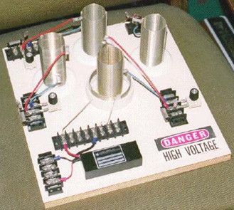 The coil in the centre of the board is a power transmitter made from a Tesla Coil constructed from two Barker & Williamson ready-made coils. Three more of the inner coil are also used as power receivers. The outer, larger diameter coil is a few turns taken from one of their standard coils and organised so that the coil wire length is one quarter of the coil wire length of the inner coil ("L2"). As before, a commercial neon-tube driver module is used to power the "L1" outer coil with high voltage and high frequency. It should be understood that as power is drawn from the local environment each time the power driving the transmitter coil "L1" cycles, that the power available is very much higher at higher frequencies. The power at mains frequency of less than 100 Hz is far, far less than the power available at 35,000 Hz, so if faced with the choice of buying a 25 kHz neon-tube driver module or a 35 kHz module, then the 35 kHz module is likely to give a much better output power at every voltage level. 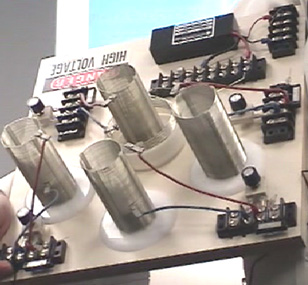 The "L1" short outer coil is held in a raised position by the section of white plastic pipe in order to position it correctly relative to the smaller diameter "L2" secondary coil. 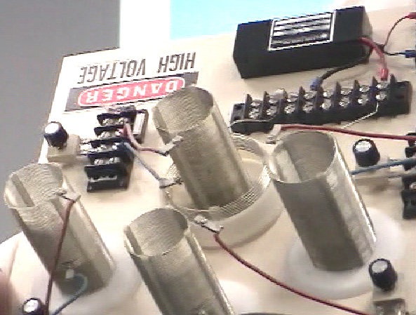 The secondary coils are constructed using Barker & Williamson's normal method of using slotted strips to hold the tinned, solid copper wire turns in place. 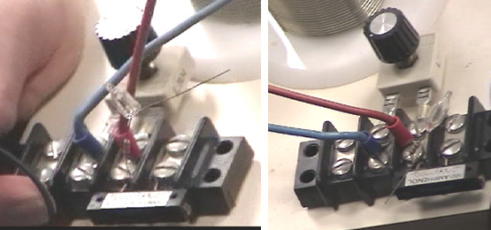 As there are very slight differences in the manufactured coils, each one is tuned to the exact transmitter frequency and a miniature neon is used to show when the tuning has been set correctly. The key feature of this device is the fact that any number of receiver coils can be placed near the transmitter and each will receive a full electrical pick up from the local environment, without altering the power needed to drive the Tesla Coil transmitter - more and more output without increasing the input power - unlimited COP values, all of which are over 1. The extra power is flowing in from the local environment where there is almost unlimited amounts of excess energy and that inflow is caused by the rapidly vibrating magnetic field generated by the central Tesla Coil. While the additional coils appear to just be scattered around the base board, this is not the case. The YouTube video demonstrates that the pick-up of these coils is affected to a major degree by the distance from the radiating magnetic field. This is to do with the wavelength of the signal driving the Tesla Coil, so the coils shown above are all positioned at exactly the same distance from the Tesla Coil. You still can have as many pick-up coils as you want, but they will be mounted in rings around the Tesla Coil and the coils in each ring will be at the same distance from the Tesla Coil in the centre. Each of the pick up coils act exactly the same as the "L2" secondary coil of the Tesla Coil transmitter, each picking up the same level of power. Just as with the actual "L2" coil, each will need an output circuit arrangement as described for the previous device. Presumably, the coil outputs could be connected in parallel to increase the output amperage, as they are all resonating at the same frequency and in phase with each other. Each will have its own separate output circuit with a step-down isolation transformer and frequency adjustment as before. If any output is to be a rectified DC output, then no frequency adjustment is needed, just rectifier diodes and a smoothing capacitor following the step-down transformer which will need to be an air core or ferrite core type due to the high frequency. High voltage capacitors are very expensive. The www.richieburnett.co.uk web site shows various ways of making your own high-voltage capacitors and the advantages and disadvantages of each type. There are two practical points which need to be mentioned. Firstly, as the Don Smith devices shown above feed radio frequency waveforms to coils which transmit those signals, it may be necessary to enclose the device in an earthed metal container in order not to transmit illegal radio signals. Secondly, as it can be difficult to obtain high-voltage high-current diodes, they can be constructed from several lower power diodes. To increase the voltage rating, diodes can be wired in a chain. Suitable diodes are available as repair items for microwave ovens. These typically have about 4,000 volt ratings and can carry a good level of current. As there will be minor manufacturing differences in the diodes, it is good practice to connect a high value resistor (in the 1 to 10 megohm range) across each diode as that ensures that there is a roughly equal voltage drop across each of the diodes:  If the diode rating of these diodes were 4 amps at 4,000 volts, then the chain of five could handle 4 amps at 20,000 volts. The current capacity can be increased by connecting two or more chains in parallel. Most constructors omit the resistors and find that they seem to get satisfactory performance. The impedance of a coil depends on it’s size, shape, method of winding, number of turns and core material. It also depends on the frequency of the AC voltage being applied to it. If the core is made up of iron or steel, usually thin layers of iron which are insulated from each other, then it can only handle low frequencies. You can forget about trying to pass 10,000 cycles per second (“Hz”) through the coil as the core just can’t change it’s magnetic poles fast enough to cope with that frequency. A core of that type is ok for the very low 50 Hz or 60 Hz frequencies used for mains power, which are kept that low so that electric motors can use it. For higher frequencies, ferrite can be used for a core and that is why some portable radios use ferrite-rod aerials, which are a bar of ferrite with a coil wound on it. For higher frequencies (or higher efficiencies) iron dust encapsulated in epoxy resin is used. An alternative is to not use any core material and that is usually referred to as an “air-core” coil. These are not limited in frequency by the core but they have a very much lower inductance for any given number of turns. The efficiency of the coil is called it’s “Q” (for “Quality”) and the higher the Q factor, the better. The resistance of the wire lowers the Q factor. A coil has inductance, and resistance caused by the wire, and capacitance caused by the turns being near each other. However, having said that, the inductance is normally so much bigger than the other two components that we tend to ignore the other two. Something which may not be immediately obvious is that the impedance to AC current flow through the coil depends on how fast the voltage is changing. If the AC voltage applied to a coil completes one cycle every ten seconds, then the impedance will be much lower than if the voltage cycles a million times per second. If you had to guess, you would think that the impedance would increase steadily as the AC frequency increased. In other words, a straight-line graph type of change. That is not the case. Due to a feature called resonance, there is one particular frequency at which the impedance of the coil increases massively. This is used in the tuning method for AM radio receivers. In the very early days when electronic components were hard to come by, variable coils were sometimes used for tuning. We still have variable coils today, generally for handling large currents rather than radio signals, and we call them “rheostats” and some look like this: 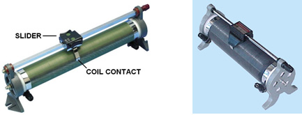 These have a coil of wire wound around a hollow former and a slider can be pushed along a bar, connecting the slider to different winds in the coil depending on it’s position along the supporting bar. The terminal connections are then made to the slider and to one end of the coil. The position of the slider effectively changes the number of turns of wire in the part of the coil which is being used in the circuit. Changing the number of turns in the coil, changes the resonant frequency of that coil. AC current finds it very, very hard to get through a coil which has the same resonant frequency as the AC current frequency. Because of this, it can be used as a radio signal tuner:  If the coil’s resonant frequency is changed to match that of a local radio station by sliding the contact along the coil, then that particular AC signal frequency from the radio transmitter finds it almost impossible to get through the coil and so it (and only it) diverts through the diode and headphones as it flows from the aerial wire to the earth wire and the radio station is heard in the headphones. If there are other radio signals coming down the aerial wire, then, because they are not at the resonant frequency of the coil, they flow freely through the coil and don’t go through the headphones. This system was soon changed when variable capacitors became available as they are cheaper to make and they are more compact. So, instead of using a variable coil for tuning the radio signal, a variable capacitor connected across the tuning coil did the same job:  While the circuit diagram above is marked “Tuning capacitor” that is actually quite misleading. Yes, you tune the radio receiver by adjusting the setting of the variable capacitor, but, what the capacitor is doing is altering the resonant frequency of the coil/capacitor combination and it is the resonant frequency of that combination which is doing exactly the same job as the variable coil did on it’s own. This draws attention to two very important facts concerning coil/capacitor combinations. When a capacitor is placed across a coil “in parallel” as shown in this radio receiver circuit, then the combination has a very high impedance (resistance to AC current flow) at the resonant frequency. But if the capacitor is placed “in series” with the coil, then there is nearly zero impedance at the resonant frequency of the combination:  This may seem like something which practical people would not bother with, after all, who really cares? However, it is a very practical point indeed. Remember that Don Smith often uses an early version, off-the-shelf neon-tube driver module as an easy way to provide a high-voltage, high-frequency AC current source, typically, 6,000 volts at 30,000 Hz. He then feeds that power into a Tesla Coil which is itself, a power amplifier. The arrangement is like this:  People who try to replicate Don’s designs tend to say “I get great sparks at the spark gap until I connect the L1 coil and then the sparks stop. This circuit can never work because the resistance of the coil is too low”. If the resonant frequency of the L1 coil does not match the frequency being produced by the neon-tube driver circuit, then the low impedance of the L1 coil at that frequency, will definitely pull the voltage of the neon-tube driver down to a very low value. But if the L1 coil has the same resonant frequency as the driver circuit, then the L1 coil (or the L1 coil/capacitor combination shown on the right, will have a very high resistance to current flow through it and it will work well with the driver circuit. So, no sparks, means that the coil tuning is off. It is the same as tuning a radio receiver, get the tuning wrong and you don’t hear the radio station. This is very nicely demonstrated using simple torch bulbs and two coils in the YouTube video showing good output for almost no input power: http://www.youtube.com/watch?v=kQdcwDCBoNY and while only one resonant pick-up coil is shown, there is the possibility of using many resonant pick-up coils with just the one transmitter. With a coil (fancy name “inductor” and symbol “L”), AC operation is very different to DC operation. The coil has a DC resistance which can be measured with the ohms range of a multimeter, but that resistance does not apply when AC is being used as the AC current flow is not determined by the DC resistance of the coil. Because of this, a second term has to be used for the current-controlling factor of the coil, and the term chosen is “impedance” which is the feature of the coil which “impedes” AC current flow through the coil. The impedance of a coil depends on it’s size, shape, method of winding, number of turns and core material. It also depends on the frequency of the AC voltage being applied to it. If the core is made up of iron or steel, usually thin layers of iron which are insulated from each other, then it can only handle low frequencies. You can forget about trying to pass 10,000 cycles per second (“Hz”) through the coil as the core just can’t change it’s magnetic poles fast enough to cope with that frequency. A core of that type is ok for the very low 50 Hz or 60 Hz frequencies used for mains power, which are kept that low so that electric motors can use it. For higher frequencies, ferrite can be used for a core and that is why some portable radios use ferrite-rod aerials, which are a bar of ferrite with a coil wound on it. For higher frequencies (or higher efficiencies) iron dust encapsulated in epoxy resin is used. An alternative is to not use any core material and that is usually referred to as an “air-core” coil. These are not limited in frequency by the core but they have a very much lower inductance for any given number of turns. The efficiency of the coil is called it’s “Q” (for “Quality”) and the higher the Q factor, the better. The resistance of the wire lowers the Q factor. Here is a copy of Don Smith’s pdf:  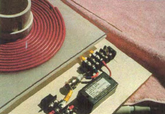 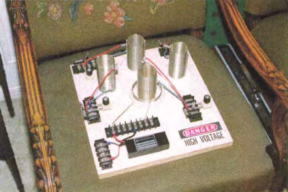 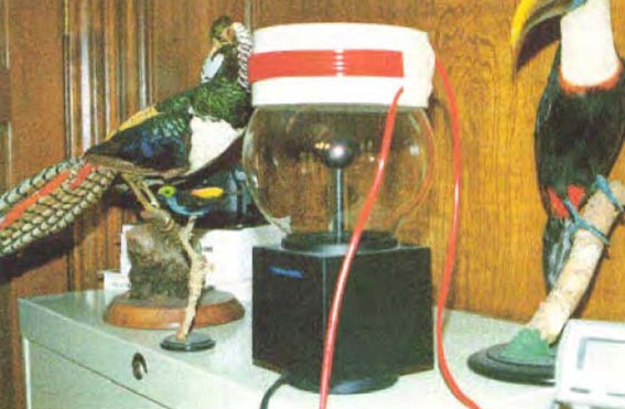             TECHNICAL FIELD: The Invention relates to loaded Dipole Antenna Systems and their Electromagnetic radiation. When used as a transformer with an appropriate energy collector system it becomes a transformer generator. The invention collects and converts energy which, with conventional devices, is radiated and wasted. BACKGROUND ART: An International search of Patent Databases for closely related methods did not reveal any prior Art with an Interest in conserving radiated and wasted magnetic waves as useful energy. DISCLOSURE OF INVENTION: The Invention is a new and useful departure from transformer generator construction, such that radiated and wasted magnetic energy changes into useful electrical energy. Gauss Meters show that much energy from conventional electromagnetic devices is radiated back into the ambient background and wasted. In the case of conventional transformer generators, a radical change in the physical construction, allows better access to the energy available. It is found that creating a dipole and Inserting capacitor plates at right angle to the current flow, allows magnetic waves to change back to useful electrical (coulombs) energy. Magnetic waves passing through the capacitor plates do not degrade and the full impact of the available energy is accessed. One, or many sets of capacitor plates, may be used as desired. Each set of plates makes an exact copy of the full force and effect of the energy present in the magnetic waves. The originating source is not depleted or degraded as is common in conventional transformers. BRIEF DESCRIPTION OF THE DRAWINGS: The Dipole at right angle allows the magnetic flux surrounding it to intercept the capacitor plate, or plates, at right angles. The electrons present are spun in such a way that the electrical component of the electrons is collected by the capacitor plates. Essential parts are the South and North component of an active Dipole. Examples presented here, exist as fully functional prototypes, and were engineer constructed and fully tested for utility by the Inventor. Corresponding parts are utilized in each of the three examples as shown in the Drawings. DRAWING 1 OF 4: VIEW OF THE METHOD N = North and S = South of the Dipole  1. North and South component of the Dipole. 2. Resonate High Voltage induction coil. 3. Dipole's electromagnetic wave emission. 4. Heaviside current component. 5. Dielectric separator for the capacitor plates. 6. For purposes of the drawing, a virtual limit of the electromagnetic wave energy. 7. Capacitor plates with dielectric in between.  Fig.2-A: 1. Hole for mounting Dipole B-1. 2. Resonate high voltage induction coil. 5. Dielectric separator, a thin sheet of plastic separating the capacitor plates 7. Capacitor plates, upper plate is aluminium and lower plate is copper. 8. Battery system, deep cycle. 9. Inverter. Input: Direct Current, output 120 Volts at 60 cycles per second. 10. Connector wires. 11. Output to point of use being the load Fig.2-B N = North and S = South component of the Dipole 1. Metal rod, being soft magnetic metal such as iron. 2. Resonate high voltage induction coil. 10. Connector wires. 11. High Voltage input energy source such as a neon tube transformer. DRAWING 3 OF 4 : Proof of Principle Device, using a Plasma Tube as an active Dipole. N = North and S = South Components of the active Dipole.  5. Dielectric separator of the capacitor plates. 7. Upper capacitor plate: upper plate is aluminium and lower plate is copper. 10. Connector wires. 15. Plasma Tube, 4 feet long and 6 inches in diameter. 16. High Voltage Energy source for the active Plasma Dipole. 17. Connector block: outlet for testing and use. DRAWING 4 OF 4: Manufactures Prototype, Constructed and fully tested.  1. Metal Dipole rod 2. Resonate High Voltage induction coil. 10. Connector wires. 17. Connector block for Input from high voltage energy source. 18. Clamps for upper edge of capacitor packet. 19. Support Device for The Dipole Transformer Generator. 20. Packet of Capacitor Plates. 21. Output connectors of the capacitor, producing energy into a deep cycle battery which then powers the inverter. BEST METHOD OF CARRYING OUT THE INVENTION: The Invention is applicable to any and all electrical energy requirements. The small size and high efficiency makes It an attractive option. It is particularly attractive for remote areas, homes, office buildings, factories, shopping centres, public places, transportation, water systems, electric trains, boats, ships and all things small or great Construction materials are readily available and the skill level required is moderate. CLAIMS: 1. Radiated magnetic flux from the Dipole, when intercepted by capacitor plates at right angles, changes to useful electrical energy. 2. A Device and method for converting for use, normally wasted electromagnetic energy. 3. The Dipole of the Invention is any resonating substance such as Metal Rods, Coils and Plasma Tubes which have interacting Positive and Negative Components. 4. The Resulting Heaviside current component Is changed to useful electrical energy. ABSTRACT An Electromagnetic Dipole Device and Method, wherein, radiated and wasted energy is transformed into useful energy. A Dipole as seen in Antenna Systems is adapted for use with capacitor plates such that the Heaviside Current Component becomes a useful source of electrical energy. 227 W. Airtex Blvd. Houston, Tx. 77090 September 23.2002 Phone: (281)876-9200 Web-site: altenergy-pro.com Fax: (281)876-9216 E-mail: donsm1@earthlink.net Dear Reader: TransWorld Energy is dedicated to improving the Human Condition in the Field of Energy which, at the same time, makes possible Healthy Water and increases the food Supply. A never-ending source of energy found throughout the universe is easily accessed with the minimum of effort and cost. The technology for doing this has been around since the 1820s. Selfish special interests have made sure that the technology remains discredited. People who control the Energy Sources control the World. Extensive research and development by TransWorld and Associates has been progressing for more than 15 years. Numerous successful Energy Producing Devices have been produced and demonstrated throughout the World. Some of these can be viewed by the Web Site located using any major search engine (such as Lycos, Yahoo, Altavista, NorthenLight and more than 2,000 others throughout the World). The Book which You are viewing has more than 40,000 copies in circulation. It has been translated and distributed in all major languages including Japanese, Arabic, Portuguese, French, Italian, Russian, Chinese, German, Spanish and many more. There are seven editions in circulation. An enormous interest is evident in the subject matter. An average of about fifty e-mails per day are received from the ends of the Earth (that is about 1,500 per month). Once the Web Site and the book are viewed, it will become evident that abundant, self- sustainable energy is available everywhere for the taking. This is natural energy which does not harm the environment or those using it. The proper Device for Collecting is all that's required. The Good News is that the problem is solved and with assistance, an ultimate source of energy which is environmentally benign, abundant throughout the universe and inexpensive to capture, is there for the taking. Thank You for your consideration _________________________ Donald L. Smith, CEO 
Description and Function: The Generation of Electrical Power requires the presence of electrons with various methods of stimulation, yielding magnetic and electrical impulses, collectively resulting in Electrical Energy (Power). In place of the mechanical - coils and magnet system, present in conventional electrical power generation, visible moving parts are replaced by resonate magnetic induction, using radio frequency. Transfer of energy by resonate induction is related to the ratio of the square of the cycles per second. The Energy System, presented here, operates at millions of cycles per second verses the conventional 60 C.P.S. This tells us that it has a frequency advantage over conventional methods. This same advantage applies to the amount of electrical energy output. Therefore the Device is small in size and produces large amounts of Electrical Energy. The Electrons acquired, are from the surrounding Air and Earth Groundings, being the same source as in conventional methods. This is accomplished by magnetic resonate radio induction. Applications: This Electrical System adapts nicely to all Energy Requirements. It is a direct replacement for all existing Energy Systems. This includes such things as Manufacturing, Agricultural, Home Usage, Office Complexes, Shopping Centers, Rail Transportation, Automobiles, Electrical Power Grids, Municipalities, Subdivisions, and Remote Areas. Briefly, the only limiting factor is the imagination. Economic Possibilities: No Historical Reference Point exists for a comparison of the Possibilities of this System. One can see from the impacted applications listed above, that the magnitude exceeds any known invention, presently a part of the Human Experience. Present and Future Plans: The Energy System has been in the developmental stage during the past seven years. It is Patent Pending # 08/100,074 with the Patent Office. No prior art exists according to the Patent Office's response. The System is presently being introduced into the World Market. Useful energy occurs as the result of imbalances in the ambient background energy, which is a transient phenomena. In the electrical field, it is a closed system subject to heat death, which severely limits it's utility. The flip side of the electron, produces magnetic waves which are an open system, not subject to heat death. These waves, being unrestricted, are the universal source of energy when unlimited resonate duplicates from this one source are available. Therefore, the key to unlimited energy, is Magnetic Resonance. In order to understand this, requires putting a stake through the Heart of Antique Physics. Non-linear and Open Systems are universally available in Magnetic Resonance Systems, Explosions of any sort [including Atomic Explosions] and Combustibles of any type. Mechanical equivalents would be levers, pulleys and hydraulics. A highly obvious example is the Piano where the Key impacts the one note giving one sound level, which resonates with it's two side keys providing a much higher sound level. Magnetic Resonance Energy clearly amplifies itself, demonstrating more energy out, than in. Ohmic resistance does not apply to Magnetic Resonance which travels unrestricted for great distances, therefore multitudes of electrons are disturbed, and their back-spin translates magnetic into usable electric energy. The right angle component which the magnetic flux provides, translates into useful electrical energy. Taken at right angles, the Magnetic Dipole provides an unlimited source of electrical energy. The writer is recognized world-wide for his knowledge and experience. See his Web Site at altenergy-pro.com . Gravity is a function of spin phenomenon as observed in gravity separation of liquids. When spun, milk and cream separate. Therefore, relative specific gravity is function of mass versus spin. Magnetics and gravity are both spin related. In part, a top levitates when spun. Therefore, spinning magnetic fields are a functional motor source as in flying saucers. ABSTRACT: Technology of New Energy: Developments in the understanding of Electricity, along with Materials which were not previously available, allows the construction of Devices which collect energy in large quantities, from the Earth's Ambient Electrical Background. This Energy is naturally occurring, environmentally benign and is available everywhere. It is available wherever and whenever it is required. New Devices use Resonate Magnetic Waves which replicate upon spinning the locally present electrons, providing multiple duplicate copies of the Energy Present. Each electron when spun yields both magnetic and electric waves in equal proportion. The electrical component is a closed system limited by Ohms Law. The magnetic component is an open system not limited and it replicates multiple copies of the energy present. Special materials and recent developments allow the magnetic energy to reproduce, through resonance, unlimited duplicate copies acquired from the ambient background. These Devices harvest the energy that has been, and is always present universally. Conventional methods consist of coils and magnets systems. Upon moving past each other, the magnetic flux field disturbs electrons which yield electricity, which is collected by the coils system. This is accomplished electronically with the new technology, without any moving parts and the energy is multiplied such that the Device becomes self-sustaining once it is started. This Technology, already presented Worldwide, will be shown at the Conference. Dr. Smith www.altenergy-pro.com e-mail donsml@earthlink.net "Putting a stake through the Heart" and thus removing the mental block created by antique physics is required. Conditions wherein this becomes necessary are non-linearity, resonance and explosions of any sort. Combustibles of any sort such gasoline and atomic explosions are good examples wherein more energy out than in, is obvious. You can add to that the non-linearity found in pulleys, hydraulics, steam power and suchlike. Magnetic resonance is a highly obvious source for multiplying energy output. The sound system present in the piano, demonstrates this very clearly. Energy amplification clearly present in the above, demonstrates the silliness attested to by many Physicists. Ohmic resistance does not apply to magnetic resonance which travels unrestricted for great distances, therefore multitudes of electrons are disturbed, and their back-spin converts from magnetic energy to usable electric energy. These same electrons have been around from the beginning of time and they are undiminished and will remain so until the end of time. Useful Electrical Energy is obtained directly from electron spin induced by incoming magnetic waves, or indirectly through mechanical exchange as in dynamo type devices. Simply put, electron spin converts from magnetic to electrical energy and vice versa. Nature provides grand scale magnetic wave induction throughout the universe, for free. In Electrical Systems, movement is at right angles to the direction of current movement. This explains the rotary movement of the Earth and other related Systems. The rate of Spin for the Earth is known as well as the mass (5.98 x 1024 Kg - "Physics for Scientist and Engineers", by Raymond A. Serway, Saunders College Publishing, 2nd Ed. page 288, Table 14.2), therefore the amount of incoming Electrical Energy which produces this action can be calculated. It can be seen quite easily, that the incoming magnetic wave energy is Vast and Continuous. As an accretion mass, the Earth is an Energy Sink, getting it's energy from elsewhere, being Cosmic, Galactic and Solar. Conversion of incoming magnetic waves into electrical energy provides an unending, inexpensive and environmentally friendly source available to all. Cosmic and Galactic Energy is available twenty four hours per day. Large amounts of this Energy accumulates in the Earth's radiation belts. This Giant Energy Storage, when properly understood, provides a major source of free unending electrical energy. Each of My Inventions plugs into this vast energy source. A perverse, Intentional Ignorance on the part of the Establishment, prevents recognition of the importance of the Energy Systems shown here. Any new system which is favourable towards the masses, is considered as disruptive, and therefore not allowed. Those who have the (Gold) Energy Rule (Golden rule ) Mandated Destruction of all Humanity is not a consideration. This Presenter will remove some of the Fog placed with the intention of preventing the recognition of this unending, environmentally clean, electrical energy Source, which is present everywhere throughout the Universe. The Cost of Harvesting and Using this Free Energy is a function of Human Stupidity. Used to demonstrate electromagnetic radiation between two UC circuits - one a transmitter and the other a receiver. When the 1.5 volt power transmitter is pulsed, the radiated signal is picked up by the remote receiver circuit which then lights up a 70 volt neon lamp. With this apparatus, the student quickly understands some basic principles governing wireless communication, broadcasting, etc. Kit: #10-416 $49.95 THE SCIENCE SOURCE WALDOBORO, MAINE 04572 P.O. BOX 727 Tel. 1-800-299-5469 info@thesciencesource.com  Diagram of transmitter and receiver coils A human is a speck of dust on Earth, the Solar System is a speck of dust in the Galaxy and in turn, the Galaxy is a speck of dust in the Universe (Cosmos). All of these respectively represent vast ambient energy reservoirs. Awareness of the Sun, opens doors into other energy sources. Electromagnetic Energy which is present everywhere throughout the Universe, is accessed by catalytic activity, directly as in Solar Cells or indirectly as by mechanical means. Resonate, Magnetic Waves (Faraday's "Action at a Distance") allow Energy Activation Transfer to remote points of usage. The method of capture and use of this Energy is optional, and therefore it's cost is a function of Human Stupidity (Free-Energy). Direct access is more desirable, and technology transfer from Solar Cell-type Devices provides the Catalyst. Enormously high Ambient Energy Levels are not detected by instruments that use the Ambient Background as a Reference Plane. A spoonful of water lifted from the Ocean does not define the Ocean. Incoming magnetic waves are reflected, Deflected or absorbed. Deflected Magnetic Waves spin electrons sideways producing useful Electrical Energy. Absorbed Wave Energy produces heat, therefore a hot interior for the Earth. In Electrical Systems physical movement is in the direction of current flow, frictional drag from inflow current defines gravity. Accretion masses resulting from Energy Sinks, provide all solid entities with their respective gravitational effect. Increasing the tolerance level for Intellectual Awakening opens Doors of Reality. These doors blink into, and out of existence, and upon recognition, benefit Mankind. Opening some of these Doors, which at the present time are seen through a deep fog, is our purpose. Exploring Unrecognized Energy Sources, which are a Part of the Ambient Background, is another goal. Our Available Instruments do not use reference planes which allow recognition of this energy, as we shall see, vast Energy Sources that totally surround us are available through Technology Transfer. They are inexpensive (Free), fully self-renewable and environmentally benign. Incoming Magnetic Wave Energy with Faraday's "action at a distance" will be looked at closely. Particle Physics will be left for the Astrophysics. Excited Electrons at point "A" the Sun (including the Galaxy and Cosmos) do not travel to point "B" the Earth, however a corresponding action occurs at point "B". The Electrons being disturbed at the Central Power Plant, in the same manner excite the Electrons at Your House, upon switching into an Earth grounding (known as "flipping the switch"). Correspondingly, there are Four Major Power Sources providing enormous amounts of Ambient Background Magnetic Wave Energy. They are The Cosmic, Galactic, Solar and Earth's Ambient Electromagnetic Backgrounds. The Earth's Electromagnetic Field comes from reflection, deflection and absorption as a result of action at a distance from the above. Prescription Physics mandates that the Earth's background is of little interest. When we have Considered the evidence herein, it will become obvious that Special Interest's effort at keeping the People ignorant has, until now, largely succeeded. Information for the entire World is available regarding the Magnetic Flux Background of the Earth's Surface (United State's Geological Survey, Colorado, USA, Office). When examined and properly understood, these Maps yield important information regarding reflection, deflection and absorption of incoming Magnetic Waves, plus action at a distance. When properly understood, these Maps reveal a very large Ambient Electromagnetic Energy Source. This is the Part of the Earth's Energy System that relates to the Bird on the High Voltage Line. When deflected, magnetic flux from electrons changes to electrical flux, providing the Motor System that spins or rotates the Earth. Physical movement by electrical systems is from inflow current movement. What level of current movement is required to spin the Earth? The Earth's Mass is 5.98 x 1024. From this Information, the Watts of Electricity Required may be calculated! Absorbed microwave flux energy heats from the inside out, therefore a hot interior of the Earth results. Water is strongly diamagnetic, and on windless days, ocean waves provide visible Proof of the overhead incoming magnetic flux. From the information above, the Earth's weight and rate of spin allows the calculation of the amount of incoming ambient background energy required. As You can see, it is not inconsequential as Prescription Physics mandates. Astrophysicist are concerned with charged particles that whiz by, once every one hundred years, rather than Wave Phenomenon associated with action at a distance. This highly Active Wave Energy translates into Electrical Energy at point "B". The Galaxy is alive With Energy which is billions of times greater than that of the Sun. Visible Light is a very tiny part of the Electromagnetic Energy Spectrum. Frequencies present in the Galaxy and Cosmos allow Radio Telescope photographs of their existence and magnitude. One such 408 MHz photograph of the Electromagnetic Energy Spectrum shows that the Earth is a tiny speck of dust in this Enormous Ocean of Energy, and can be seen near the left end of the Central High Energy Area. This Energy extends in all directions. Accretion and formation of Planets, Suns and Galaxies are results of energy sinks and variable sized black holes. Mass retains heat, and is cooked from the inside out by the microwave background energy provided by the Universe. Flux movement into energy sinks, provides the frictional force know as gravity. Spinning mass in the presence of incoming flux amplifies the gravitational effect. At present, only Solar Energy is recognized. It is inconsistent, flaky and a very small Part of the Magnetic Wave Energy Present. Technology Transfer from Solar Power provides uncomplicated and inexpensive, direct access to the Other Greater Energy Sources. All Electromagnetic Energy harvesting methods include a Catalyst, a Collector and a Pump. Catalysts include sensitization through doping with certain elements, air and earth groundings. Collectors include temporary storage as in Capacitors, Coils and Transformers. The Pump System includes induced movement onward to the point of use. Conventional rotating coils and magnet systems activate electrons present, such that action at a distance can occur, therefore it is an energy activation pump. In Direct Access Systems such as Solar Cells, the same occurs without mechanical action. Direct access occurs when Magnetic Waves impact a catalyst, spinning the local electrons sideways, producing useful electrical energy. Indirect acquisition of electrical energy by mechanical means is wasteful, troublesome, expensive and degrades the environment. The dynamo is a combination collector and pump of energy which is collected from the Earth's Ambient Energy Background. Generators do not. make electricity, they collect it from the Ambient Background and forward it, as in Faraday's "action at a distance". Energy Conservation Laws relating to these systems, relate to grey areas, and when understood, are excluded because of the existence of External forces, open and non-linear systems as per Einstein. The Knowledge Base just viewed, provides a Direct Understanding of the Requirements for Harvesting of unending, fully renewable, environmentally benign Sources of Electrical Energy. Suggestions for Construction This is the Basic Sonar Power System which permits submarines to see approximately 50 miles distance. What is not commonly known is that it works better at higher frequencies in the Gigahertz range. Any Device that can radiate 50 miles plus, is producing an enormous el ectromagnetic disturbance from a small input into a rod of magnetostrictive material. Disturbing the Earth's Ambient Background plus the strong dipole being produced, turns the magnetostrictive rod into a combination of a receiving antenna and a vastly superior output transformer. The Drawing is only the Key Unit. A power input module and an output inverter circuit (diode bridge plus output transformer) are also required. The metal core and the wire size of the output transformer, plus adjusting the Earth Grounding of the Load, will determine the Amperage. The Ideal rod material is Terfenol-D (check the internet). However a 1.5" diameter 10" long rod, costs over $5,000 each. Less expensive alternatives are obvious. When constructing, use PVC tubing with removable caps. Wind the coils on it and insert the experimental rod. Use only magnetostrictive material. When you get it right, you will have exactly what the Doctor ordered:  Diagram of transmitter and receiver coils Magnetostriction oscillators work by magnetic resonance in a rod of magnetostriction material. This rod serves two purposes: It vibrates at the frequency of resonance oscillation, and it becomes the feedback transformer. Frequency is determined by items 4, 5, 6 and 8. The diameter, length and volume of the rod and output windings, determines the output. Item 2 provides feedback into the system. The negative magnetic character of item 8 plus the windings 2, in reaction to the magnetic flux field provided by 9, increases (amplifies or magnifies) the output. Magnetic permeability is the counterpart of negative resistance. Resonating with negative magnetic resistance, it pumps energy from the Earth's ambient background. Magnetic permeability is the ratio of flux density (Earth's B field) to the magnetizing force (H) in oersteds. Magnetostrictive materials are piezoelectric in character, and have a very high resistance to electrical current flow. Examples are: 1. Permealloy Negative Magnetic Permeability > 80,000 2. Sendust Negative Magnetic Permeability 30,000 -120,000 3. Metglas Negative Magnetic Permeability > 200,000 4. Iron with (34%) Cobalt Magnetic Permeability 13,000 5. New Technology Magnetic Permeability > 1,000,000 1. DIRECT Faraday's "Action at a Distance" incoming magnetic wave conversion to useful electrical energy. This includes Cosmic, Galactic, Solar and Magnets. Technology Transfer is from Solar Cell Technology. 2. INDIRECT Electron Stimulation-Induced Electron Spin Systems, Electron Avalanche Pumping Systems Primitive Indirect Conversion from another form of energy. Coils and Magnet as in Dynamo Systems (Closed Systems). Chemical Systems, Atomic, Pons & Fleischman and etc. Advanced Direct Conversion, Magnetic Wave ( Open Systems ). Ambient Sources Air Core Coil Systems Gaseous Tube Systems, Solid State Marx Generator Avalanche Type Systems. Leyden Bottle Capacitor Types inserted in Lakes and other. Magnet Systems Electron Beam Antenna Systems 3. TRANSFER MECHANISMS Solids - as in metal conductors Gaseous as in radio wave transmission, a form of ionization. Sensitizing of Systems by use of Trace Doping with Radioactive elements, includes metal surfaces. Open Systems, non-linear with external forces. Albert Einstein in a direct quote from his biography states that these are excluded from the conservation of energy laws. Closed Systems Maxwellian Type Systems. Mathematics are predictable requiring deductive reasoning. Ohm's Law is King, and Establishment Intellectuals being comfortable with this, brand all else as a violation of the Laws of Nature by obtaining something for nothing. This is Dishonesty grand mal.  A deep fog pervades the entire Scientific Community with regards to the Significance of the Above Energy Sources. Magnetic Waves convert directly into Electrical Waves (useful electricity). Two sides of the electromagnetic system are always present and never separate. Local electron spin provides (action at a distance) the flip side of the incoming magnetic wave energy. Enormous amounts of incoming magnetic wave energy becomes a part of the Ambient Background, and as such, cannot be measured directly. Reconstruction from indirect information, allows us to establish the actual energy levels which are present. Instruments provided by the Scientific Community measure only point "A" to "B", and when both are ambient, no potential energy is shown. This is the "bird sitting on the million volt power line and sensing nothing" approach. The Earth's actual ambient background has as it's Energy level multi-billions of Volts, which are conveniently and obliviously ignored by the scientific community. When properly understood, this enormous, never-ending source of environmentally-friendly energy becomes available.  Don L. Smith, Energy Consultant At a meeting between J.P. Morgan, Edison and Tesla, Tesla proposed an Electrical Energy System which could he connected into directly, without using a meter. Tesla's Idea of "Free Energy" was not compatible with their thinking. Courtesy of Morgan and Edison, from that day foreword, a complete and total bastardization of the Idea has been in progress. Agents for Morgan and Friends include the U.S. Patent Office and Academia. Academia's bad habit of incestuous quoting of each other, eliminates them as a possibility in cleaning up the mess. This selective ignorance, permeates throughout the study of electricity. Many people, otherwise known as "intellectuals", have a total blackout and become jabbering idiots when "free-energy" is mentioned. The term has been amended to say, "something which was never there is being harvested and that this violates the laws of physics". For the selectively ignorant, this seems the way to run. Those who choose Morgan's drum beat, have severely limited the possibilities built into electricity. This paper will be an exercise in creative understanding, in placing updated knowledge at your disposal. Whether it becomes a useful tool or is selectively ignored is your choice. Electrons are defined as being the practical source of electrical and magnetic energy. The electron as a particle, was postulated by professor J. Thompson in early 1900's. It is now universally accepted that the electron exists and that it is the source of electricity. When the electron is agitated it produces magnetic and negative electrical energy. Physics as it exists today, cannot explain why the electron remains intact and is not diminished by the energy it releases. This is a part of the built-in ignorance provided by the Morgan and Edison Camp. One volts worth of electrons, when cycled, yields one volts worth of electricity. This can be repeated continuously forever and it never deplete or diminishes the electrons in question. They simply return to their air and/or earth source, waiting to do the whole thing again and again. Therefore, electrical energy is available, anywhere and everywhere humans go. People who intercede for profit, set the cost of electrical energy. Otherwise, all electrical energy is free, Morgan and Edison be damned. Improving upon Professor Thompson's postulation, other obvious characteristics can be seen to further define the electron. It has both magnetic and electrical emanations resulting from a right-hand and left-hand spin. Since magnetism and amperage come as one package, this suggest, that electrons in their natural non-ionic state, exist as doublets. When pushed apart by agitation one spins and supplies electricity and the other spins and provides magnetic (amperage) energy. When they reunite, we have Volts x Amperage = Watts. This Idea, until now, has been totally absent from the knowledge base. The number of times that an electron is cycled, sets the collective energy potential present. The electrical equivalent of E = mC2 is E = (Volts x Amperes) x (Cycles Per Second)2. Those who choose, are now free to head for the bushes and make their usual contribution to humanity. Prior to Tesla, there was a large group of people in Europe, who were building resonant coil systems for medical use. Amperage was dangerous in their coil systems. The Tesla Coil is only the Voltage half of their coil system, as will be demonstrated. A short list of those (from 1860 onwards) active in resonate high frequency coil systems include; the Curies, Roentgen, Ruhmkoff, Oudin, Hertz, Levassor, Dumont, D'Arsonval and many others. Peugeot, Panhard-Levassor, Bollee, Renault and others had successful electric automobiles in production using A C. motors. Various electrically-powered airships, including the Dirigible "France" were in service. D'Arsonval, Professor of Experimental Medicine at the College of France, invented the electrocardiograph, oscilloscope, amp and volt meters, thermography and numerous other medical applications of high frequency electricity. As early as 1860, he was building high frequency coil systems, which he used in his experimental work. There is a strong connection between the work of Tesla and the people mentioned above. Electric vehicles of all sorts, dominated until the 1920s, when the electric starter motor made the internal combustion engine practical. Prior to that, upon cranking, it frequently would break the owner's arm. At that point the use of batteries as a source of power was replaced by oil. The establishment's carpet has some rather large lumps under it. Coulomb's and Newton's inverse square law is politely ignored and it's opposite is allowed to have only the most abstract status. Without opposites we have no definition. The source value of a remote flux reading, requires the squaring of the distance, times the remote reading, to obtain the original value. The opposite of this, being the derivations relate to Energy equals Mass times the Velocity constant squared. The electrical equivalent, being Energy equal capacitance times voltage squared and Energy equals induction times amperes squared. Flux lines increase as the law of squares and then activate electron energy which was not previously a part of the sum. The cumulative capacitance and inductance increase as the outer ends of a Tesla coil are approached, and this results in output energy being greater than the input energy present. This Energy is real. It can be safely measured by magnetic flux methods and electrostatic voltmeters, based on the inverse square law As seen above, flux lines result both from induction-henrys-amperage and capacitance-coulombs-volts, and define electrical energy. The non-linearity of this system does not obey Ohm's law, which is replaced with impedance and reactance for alternating current systems. Impedance is the sum of the system's resistance to AC current flow, and this becomes zero at resonance. In resonant induction systems, a cycles-per-second increase, invokes a second round for the law of squares. The degree to which flux lines are present, disturbs an equal amount of electrons, upsetting the ambient background energy, resulting in useful electrical energy being obtained. The frequency at which the disturbance occurs, increases the useful energy available, and it obeys the law of squares. Two square-law components, flux density and frequency are involved. Enter resonance which cancels the resistive effect. Only the electrical energy which is either above or below the ambient level is useful. For the Central U.S. going east to west, ambient as approximated by electro-static voltmeters and flux methods is 200,000 volts on a solar-quiet day. At night time, the ambient energy level drops to about one half of the daytime value. On a solar-active day, it may reach more than five times that of a solar-quiet day. Ambient background energy at the polar regions, is approximately 500,000 volts on a solar-quiet day. The background energy varies as it relates to the North-South component and the East-West continuum. This leaves us with an interesting problem. Electrons, when disturbed, first produce magnetic flux and then produce electrical flux when they spin back to their normal position. Therefore any electron movement produces above ambient energy, being over unity. 1. Current-amperes results from the unequal distribution of negativity (electrons). 2. Electron spin causes electrical current and magnetic lines of force. 3. Magnetic imbalance causes the gravitational effect. This is evidenced in electric motors by magneto-gravitational displacement of mess, which causes the motor to rotate. FIELDS & WAVES * 
* Below 20,000 Cycles Per Second = Fields Above 20,000 Cycles Per Second = Waves (Radio Frequency) Analogous Relationships: 1. Potential Power is present in a bar magnet as shown:  2. The Source of these Electrons being from the Solar Plasma, are non-ionic and occupy all Free Space. They are commonly obtained from Earth and Air Groundings. They exist in Doublet Pairs, one being more negative than the other. The more negative one has a Left Hand Spin. The less negative one has a Right Hand Spin. 3. Resonate Electrical Coil Systems (Tesla ) are Analogous to the System observed in the Bar Magnet (above). The Bloch Wall Area is Located at the base of the L-2 Coil. The Left Spin portion of the coil (Voltage Only ) Coil predominates. The Right hand Spin portion of the coil (Magnetic-Amperage) is mostly absent.  Collection and transfer of energy requires temporary storage, which occurs as capacitors and coils of a resonant circuit are cycled, on and off. The frequency at which the capacitors and coils are pumped, determines the amount of electrical energy that moves onward. The amount of Energy transferred relates directly to the density of lines of flux present. The Kinetic Energy Formula is helpful in establishing the amount of energy present. This formula squares the velocity times mass. In the case of electrical energy, the intensity of voltage and amperes multiplied by the cycles per second, replace the velocity component. Note that the "acceleration" of the Voltage "E" and Amperage "I", which increase as non-linear components, then obeys the Law of Squares. Each unit of increase, causes a squaring of the flux lines present. The amount of energy transfer caused by this increase in flux lines is demonstrated below.  In resonant air-core coil energy transfer, the increase in flux lines present disturbs more electrons than previously, resulting in over-unity energy being present and available. Energy stored, times the cycles per second, represents the energy being pumped by the system. Capacitors and inductors store electrons temporarily. Capacitor formula: W = 0.5 x C x E x Cycles per second where: W = energy in Joules (Watt Seconds ) C = capacitance in farads E = applied potential in volts squared. Inductor (Coil) formula: W = 0.5 x L x I x Cycles per second where: W = energy in Joules (Watt Seconds ) L = inductance in henrys I = current in amperes squared Both one henry, and one farad, equal one volt. The higher the cycles per second, including the squaring of the flux lines, cause a large increase in the amount of energy being produced. The above combined with a resonant energy induction system (where all electrons are moving in the same direction at the same time), make the next move into over-unity practical. The dampening process of conventional electrical power generation, has all the available electrons bouncing randomly, mostly cancelling out each other. In that System, the useful energy available is a very small percentage of the energy which is present. In the resonant induction system, a very high percentage of the energy present is useful. At resonance, (ohms-impedance-Z) becomes zero and all of the energy present is not degraded and becomes available to do useful work. "Ohms" is load or wasted energy, and "amperes" is the rate of that wasting of energy. Using the previous information, if we now apply it to an air-core coil, resonant transformer energy system. L-1 and L-2 coils are now present. L-1 has a smaller number of turns and is several times the diameter of L-2. Input from a 12 volt high-voltage laser driver source, produces 8,000 volts with a low level of wasted energy, pushing amperage into, say, 4 turns of coil L-1. Each turn of the L-1 coil then acquires 2,000 volts of resonant potential. Consequently, each turn of L-2 is then exposed to the electric flux of 2,000 volts. Each turn at the bottom end of L-2 acquires 2,000 volts. The flux lines are squared and are additive as the voltage and amperage progresses towards the top end of L-2's large number of turns. A huge number of additional flux lines which were not previously present become present at the top end of the L-2 coil. These flux lines excite the nearby electrons in it's earth and air and groundings. This high level of excitement above the ambient, causes a large number of electrons which were not previously a part of the energy present, to become available for use. At this point over-unity is present in large amounts. The "bubble gum between the ears" response to this is: "this must be lots of volts but no amperes". Please recall that amperage is wasted energy, and that until that wasting occurs, there are no amperes. A good way to demonstrate this, would be to let the bubble gum crowd put their hands on the high-voltage end of the device while standing on wet ground (a people zapper). Note: don't do this. This over-unity device produces energy at radio frequencies which range into the megahertz band. This allows the device to be small in size, and yet produce large amounts of energy. A megawatt-sized unit will sit comfortably on a breakfast table. This energy is changed to Direct Current and then switched to produce the desired working frequency AC  1. Random movement of electrons in "A" and "B", mostly cancel each other out. This dampening, or wasteful concept of energy, is a source of much pleasure for the establishment. 2. "C" (Volt, Amperes, Reactive "V.A.R."), is the situation where all of the electrons move in the same direction at the same time. This results in near-unity energy output by resonant induction transfer. 3. Resonant induction transfer from one isolated power system, allows other resonant induction systems to duplicate the original source, which in no way diminishes the original source. Air-core coils (isolation-transformers) confirm this when they are a part of one of these functioning systems. A less perfect illustration would be the fact that the number of radio sets tuned to a particular radio transmission, does not alter the power required at the radio transmitter. 4. Resonant induction transfer, disturbs a large number of adjacent electrons which were not a part of the original input power source. The pulsating-pumping effect then draws in the newly available additional electrons into the on-going energy generation system. A near unity energy system of resonant air-core coils and the extra acquired electron-energy source constitute an over-unity system. Useful Electrical Power is Generated when Electrons from Earth and Air Groundings are disturbed by the movement of coils and magnets with reference to each other. The resulting electrical and magnetic energy is then changed to joules [watt-seconds: Volts x Amps x Seconds]. Each forward electron movement results in a magnetic impulse and each return movement causes an electrical impulse. The composite of the electrical energy impulses from these electrons yields useful energy [Power]. Let the above electron movement be represented by a room full of ping pong balls bouncing randomly. Most of the energy present cancels out by random impacts. This is the Classic Under-Unity approach to Electrical Power Generation, sanctioned by the Establishment. In contrast to that, in the Electrical Energy Generation System presented here, the resonant Electrons are all moving in the same direction at the same time. This allows Near-Unity Electrical Power to Develop. This is the room-temperature equivalent of super conductivity. The Energy System presented here, consists of a properly-adjusted and functional resonant air-core coil tank. The magnetic energy is stored in the coil system and the Electrical Energy is stored in capacitors. From Maxwell and others, we know that electrical-related energy has an equal amount of magnetic energy associated with it. "The formula which establishes the Useful Energy of the System": Joules = 0.5 x C x V2 x (Cycles Per Second)2 units: Joules (Volts x Amps x Seconds) Watt Seconds where C = Capacitance in microfarads V = Potential in Volts The transfer of Electrical Power by Resonant Induction is a direct function of the squaring of the cycles per second. For example, square 60 C.P.S. and then square the radio frequency C.P.S.s of the System here presented. Obviously, One Million Cycles per Second transfers more energy than Sixty Cycles per second. The Sanctioned Method of Electrical Power Generation uses the 60 C.P.S. Method. Using 60 C.P.S. and the random scattering of the Electrons System, assures the Establishment of it's desired Under-Unity Goal. This random bouncing of the Electrons is the Ohms of Ohm's Law and is used to establish the rate of dissipation and/or Load [Work]. In the Resonant Tank Induction Energy Transfer System presented here, Impedance [system resistance] replaces the conventional ohm's usage. At Resonance, impedance becomes zero and the full force and effect of the Energy Transfer occurs. This is superconducting conditions at room temperature. At radio frequency the Electrons do not pass through the conductor as they do at lower frequencies. Instead, these Electrons encircle the conductor and are free of the conductor's resistance. Let the Establishments Power Generation System be called 'A" and the System presented here be called "B". With "A": Given 60 C.P.S. at 120 Volts using a 10 microfarad Capacitor: Joules = [0.5 x 0.000010 x 120 squared] x C.P.S. squared (120 x 120 = 14,400) [0.000010 x 14,400 = 0.144] [0.144 x 0.5 = .072] (0.072 x 3,600 = 259.2] Using the Inventor's Resonant Induction System, the Electrical Power available would then be 259.2 Joules [Watt-Seconds]. Using the Establishment's method only permits less than 10 Watt-Seconds of Useful Electrical Energy. "B". Given One Million Cycles per second at 100,000 Volts, using a 10 microfarad Capacitor. Joules = [0.5 x 0.000010 x 100,000]2 x (C.P.S)2 (100,000 x 100,000 = 10,000,000,000) [0.000010 x 10,000,000,000 = 100,000] (100,000 x 0.5 = 50,000] (50,000 x One Million squared = 50,000,000,000,000,000) The useful Electrical Energy available is greater than 50 Mega Watts. Since the Resonant Electrons are non-impacting, all of the Energy is available for direct usage. 1. Induction Energy transfer is enhanced by the squaring of the cycles per second produced by the System. 2. Induction Energy transfer is enhanced by the squaring the input voltage and amperage. 3. The increase of the flux lines occurring from the above, disturbing more electrons, causes more electrical energy to become available. 4. Resonant Induction has all of the Electrons moving unimpeded, resulting in superconductor conditions at room temperature. 5. A smaller amount of energy is used to disturb a larger number of Electrons. Electrons not originally a part of the System then contribute their energy, resulting in a net gain in available usable power. 6. The physical size of the System [Device] is small. The Device described in "B" sits comfortable on a breakfast table. 7. A small energy source is used to start the device and that source remains fully charged at all times by the System. 1. Use of Logarithmic Scales on electrical measurement instruments. Linear measurement works fine where Ohm's Law applies (direct current). In alternating current, ohms are replaced by impedance and the measurements become non-linear. 2. Infinite "Q" at resonance confirms that voltage and amperage is squared, as in the kinetic energy formula. See the formulas of this report. 3. Square waves are clipped infinite "Q"s. 4. Maxwell and others show that magnetic-inductance-amperage and electrical-capacitance-voltage are two sides of the same coin. Magnetic-inductance is directly equal to amperage. Both obey the Law of Squares, which has over-unity built in. 5. Magnetic and electrical flux are present in enormous amounts at the outer ends of an operating Tesla Coil. 6. Ignorance of how to measure and relate magnetic and electrical flux, is the chief weapon of the under-unity gaggle. 7. The Cumulative inductance and capacitance of the Tesla Coil grounds itself out, if not properly utilized. See this report for the temporary energy storage accessible, when properly managed. 8. The Patent Office refers devices related to over-unity to their metering group, which is a sure indication that they are aware and accept the logarithmic measuring devices. This is direct and absolute evidence that they accept the square law as it relates to kinetic energy. This also indicates they are aware that over-unity exists. Since their bureaucratic brain is improperly motivated they continue to badger inventors who are working in the over-unity arena. Their level of intellectual dishonesty is sanctioned by, and is a real part of doing business with, a government which prides itself in being a hooliganistic bureaucracy. 
Donald L. Smith Energy Consultant Energy, energy everywhere and not a Joule to Jounce. Conventional wisdom, when properly tuned will appreciate the nature of energy, as here presented. The basic unit of electricity (the electron) upon encountering a moving magnetic field (or wave) spins, giving off an electric impulse. When this impulse collapses, it spins back to it's natural position, giving off a magnetic impulse. Therefore, magnetic and electric are two sides of the same coin. When the magnetic side is pulsed, it yields electricity and conversely, pulsing of the electrical side yields a magnetic field. Moving one in relation to the other produces useful energy. When done consecutively, each cycle pushes (current) forward, while pulling electrons into the system... in much the same way as a water pump moves water. These electrons are obtained from Earth and air grounding. The word "electric" comes from the Latin word electron "amber". When rubbed, amber develops an electrical charge, which can be transferred to a dissimilar substance. During the seventeenth and eighteenth centuries, a great deal of attention was centered on this attribute of amber. Amber was used to differentiate the non-metals. Carbon-related substances and other non-metals, when subjected to friction, give up negative electrical charges. On the other hand, metals when subjected to friction, simply conduct the charge. It is important to note that approximately 70% of the Earth's exposed crustal portions (surface) consist of silicone-related non-metals (electron donors) and become a direct source of electrical energy when properly agitated. Useful electrical energy can be obtained by grounding into the Earth's non-metal crust and into it's atmosphere as a natural source of electrons. These electrons have accumulated from the solar plasma during the aging of the Earth for more than 4.5 billion years, at a rate exceeding 3.9 exajoules per year This indicates that the Earth's electrical field contains in excess of 17.6 x 10¹⁸ of cumulative exajoules of energy. One exajoule is the approximate energy equivalent of 125 million barrels of oil. The electrical energy in one display of lightning is approximately ten trillion joules. During each 24 hour period, the land portions of Earth's surface yields in excess of 200,000 emissions, which involves more than 2,000 quadrillion watts. C.F. Gauss (1777-1855) and H.C. Oersted (1777-1851) were each separately trying to define the Earth's electrical field with all external influences removed. These external influences being solar-quiet periods and being remote from the land's surface. The air electricity background which they measured varies with latitude. Their European measurements correspond to approximately the latitude of Washington. D C. They were measuring magnetic field flux as an indicator of negative electron energy active and present. A related family of measurement are now presented. Units of measurement used to define flux fields include Gauss (one unit = 100,000 volts), Oersted (one unit = 50,000 volts), Tesla (one unit = 10,000 Gauss) and Gamma (one unit = 1/10,000 of a Gauss). Much confusion exists in electrical related publications about these units. As presented here they are correct with values taken from their original definitions. The entire surface of the Earth has been surveyed by aerial magnetometer, in most cases using gamma or nano teslas. One gamma is the magnetic flux equivalent of 10 active volts of electricity. When the data is corrected for flight height it becomes obvious that there are numerous areas where the gamma readings exceed one trillion gammas. Lightning strikes from the ground up are in that energy range. With knowledge of these electron enriched areas, the quality of Earth grounding, becomes enhanced. The correction necessary for land surface data when acquired from aerial magnetometer maps (using Coulomb's law) requires that the remote distance be squared and then multiplied by the remote reading. As an example, if the remote reading is 1,600 gammas and the flight height being 1,000 feet. Take 1,000 x 1,000 = 1,000,000 x 1,600 gammas = 1.6 trillion gammas x 10 volts = 16 trillion volts equivalent for land surface data. Present day methodology requires mechanical energy in exchange for electrical energy. Once obtained, this energy is subject to Ohm's Law. Present Methodology obtains it's electrical energy from it's non-metal and air groundings. This same energy can be obtained without the wasteful mechanical approach and at a much, much lower cost. Any required amount of electricity is available by resonant induction transfer from the Earth's magnetic and electrical fields. The major difference is in the functioning of Ohm's Law in relation to resonant circuits. In the resonant induction system suggested here, system resistance (Z) becomes zero at resonance. Therefore, Volts and Amperes are equal (V.A.R.) until work (load) is introduced. Each cycling of this resonant induction system pulls in additional electrons from the Earth's electrical field, generating electrical energy in any required amount. In this system, a small amount of electrical energy is used to activate and pull a much larger amount of energy into the system. This electrical advantage corresponds to the pulley and lever of the mechanical world. The electrical system presented here is extremely efficient. Using present methodology as a basis for comparison, with it's 60 cycles per second system. The resonant induction system, cycling at 60 million times per second produces one million times the energy which is produced by the present energy systems. A single small size unit of the resonant induction system has more usable electrical output than a major conventional unit. The radio frequency energy produced is easily changed to Direct Current, and then to the present 60 cycles per second system in preparation for commercial usage. The Patent Pending on this system is #08/100,074, "Electrical Energy Generating System", dated 4 February, 1992. Definitions: One Joule is one watt for one second One Watt is one volt ampere V.A.R. is Volt Amperes Reactive Additional Reading: Electricity and Magnetism by B.I. Bleany and B. Bleany Oxford University Press 1991 ISBN. 0-19-851172-8 Engineering Electromagnetics by W. H. Hayt. Jr. McGraw-Hill 1989 ISBN. 0-07-027406-1 Energy Methods in Electromagnetism by P. Hammond Oxford University Press 1986 ISBN. 0-19-859368-6 Energy in Electromagnetism by H. G. Booker Institution of Electrical Engineers by Peter Peregrinus Ltd. 1982 ISBN 0-900040-59-1 The American Radio Relay League Handbook for 1992 and 1993. 69th and 70th editions. Published by The American Radio Relay League. (For V.A.R. information) ISBN. 0-87259-169-7 Electron Paramagnetic Resonance, Techniques & Applications by R. S. Alger, U. S. Naval Radiological Defence Laboratory, San Francisco, California. Pub. Interscience Lib. Congress #67-20255 Geomagnetic Diagnosis of the Magnetosphere by A. Nishida, University of Tokyo 1978 Pub: Springer-Verlag ISBN. 0-387-08297-2 Energy and The Missing Resource by I. Dostrovsky. Pub: Cambridge University Press 1988 ISBN. 0-521-26592-4 High Voltage Measurement Techniques By A. Schwab, M.I.T.. 1971 I S.B.N. 0-262-19096 Environmental Magnetism by R. Thompson & F. Oldfield Pub: Allen & Unwin, London 1986 ISBN. 0-04-538003-1 Geo-electromagnetic Investigation of the Earth's Crust and Mantle. Translated from Russian, By I. I. Rokityansky. Institute of Geophysics, Kiev, U.S.S R. Pub: Springer-Verlag 1082. ISBN. 3-540-10630-8 Electron Paramagnetic Resonance of Transition Ions by A. Abragam and B. Bleaney Dover Publications, New York, N.Y. 1986 The Electromagnetic Field by A. Shadowitz, Dover Publications, New York, N.Y. Geomagnetism, Several Volumes, Pub. Periodically by J.A. Jacobs, Institute of Earth Studies, Dyfed, U.K. Pub: Academic Press 1989-1990's. Geomagnetism by S. Chapman and J. Bartels, 3 Volumes Oxford University Press, 1940 Physics of Geomagnetic Phenomena, Several Volumes by S. Matsushita and W. H. Campbell National Center for Atmospheric Research, Boulder, Colorado Library of Congress #67-23168 Pub: Academic Press, 1967 Physics Problems and How to Solve Them by C. E. Bennett, Professor Emeritus of Physics. University of Main (Particularly the sections on Electricity and Magnetism, and Units of Measure). Pub: Harper & Row ISBN. 0-06-460203-6 Units and Standards for Electromagnetics By P. Vigoureux, National Physical Laboratory Pub: Springer-Verlag 1071 ISBN. 0-387-91077-8 Surveyor's Guide to Electromagnetic Distance Measurement. Edited by J. J. Saastamoinen, Canada Pub: University of Toronto Press Electromagnetic Distance Measurement by C. D. Burnside Pub: Granada, London 1971 ISBN. 0-258-96793-5 Der Magnetische Kreis "The Magnetic Circuit" By Von Heinz Rieger of Siemens AG. 1970 Berlin and Munchen, Germany I.S.B.N. 3-8009-4719 6 Electronic Modelling of Power Electronic Converters by J. A Ferreira Pub: Kluwer Academic 1989 33 AH Dordrecht, The Netherlands I.S.B.N. 0-7923-9034-2  With alternating electrical current, electrons do not move from point "A" to point "B" as commonly envisioned! Electrical potential (oscillating electrons) at point "A", results in harmonic electron activity at point "B", when the grounding switch (circuit) is closed. That is to say, point "B" supplies it's own electrons and mirrors the activity of point "A". Impulsing (turbulence) by magnetic induction causes electrons to be pulled into the system, which then oscillates. When the magnetic field collapses (becomes absent) the electrical potential returns to it's natural background level. Several major flaws are present in the conventional 60 cycles per second method of electrical power generation and it's iron core transformer system. This system is handcuffed by the inverse relationship of volts to amperes. This represents a stodgy, inflexible inheritance, courtesy of Mr. T.A. Edison and his concept of electrical power generation. Nikola Tesla stood, almost alone, against Edison and managed to prevail with his Alternating Current system. Without the alternating current system, electronic things in the modern sense would not exist. This report will be concerned with some of the extensions and benefits of the alternating current electrical system. This study will limit it's scope to air core coil transformers at radio frequency and upwards. The electrical power produced by this method is inverted to Direct Current and then to Alternating Current as required for popular usage. There are several important advantages of this system over conventional power generation. Start with two coils (separate-apart), one being a reactor coil (L-1) and a second coil (L-2), being the reactant coil. Magnetic field fluxing (off-on of the electrical source) causes inductive reactance of L-1 which replicates by induction in L-2. Pulsing of the magnetic field (from L-1) in the presence of L-2, generates electrical potential. For example, should the L-1 coil have ten turns, with an imposed AC. potential of 1,200 volts. This results in each turn of L-1 acquiring 120 volts of potential. This induced magnetic field, then replicates itself in each turn of the L-2 coil. The L-2 coil may have one or many hundreds of turns. Modern encapsulation techniques makes high frequency and high energy controllable. Let's take another important step in this air-core transformer process. For purpose of discussion, let the value of inductive reactance at 60 cycles per second, equal one. Each time the frequency is doubled, the effectiveness of induction is squared. At about 20,000 Hz, when radio frequency is achieved, the electrons begin spinning free, outside of the inductor and they become increasingly free of the inverse relationship of volt-amperes. From this point on, they replicate by the inductive process as V.A.R.. That is to say, volts and amperes are equal, until resistance (work) is introduced. Therefore, additional, not previously available electrons become incorporated for a very large net gain in potential. This gain is real ! The quality of the grounding system determines the effectiveness of this method of producing electricity. A handy reference to locate the negative grounding areas for power generation can be found in the Aeromagnetic Map Studies of the US Geological Survey. They provide an excellent method for locating the best sites for optimum negative grounding areas. When this method is combined with the induction coil system, already described, it provides an electrical power generating system millions of times more efficient than any known conventional method. This new system ("E.E.S. II") is uncomplicated, physically small and it is inexpensive to build. The technology required for it's construction already exists. Maintenance is near zero, as there are no moving parts. Once operating, this system could last forever. Small mobile E.E.S. II units are already available as replacements for the batteries used in electric automobiles. Larger E.E.S. II units can be provided as a replacement source of power for hotels, office buildings, subdivisions, electric trains, manufacturing, heavy equipment, ships, and generally speaking, any present day application of electrical power. The system consists of three separate modules. Reverse engineering is used in matching the modules to the desired usage. HIGH VOLTAGE INDUCTION TRANSFORMER MODULE: 1. Preferably an off-the-shelf-unit similar to a TV flyback and/or automobile ignition type related coil (transformer). 2. Ratio of input to output may be from less than 1:100 to greater than 1:1,000 A voltage tripler may then be used. 3. A connection allowing the high voltage output to pass onward through the induction coil L-1 and then to it's grounding. AN AIR CORE INDUCTION COIL TRANSFORMER MODULE: 1. There are two coils: the reactor coil L-1 and the reactant coil L-2. L-1 has a high voltage radio frequency capacitor between it and it's grounding. 2. Input into the L-1 inductor is divided by the number of turns in it. The magnetic flux field provided from each turn of L-1 replicates itself as an electrical potential in each turn of L-2. 3. L-2 may have one turn or many hundreds of turns. The net gain depends upon the number of turns in L-2. Output from L-2 is in V.A.R. With this type of output, volts and amperes are the same until work(resistivity) is introduced. THE INVERTER MODULE: 1. Inverts to direct current (D C.) 2. Inverts to alternating current (A C ), as desired. 3. Provides customized output of electrical power ready for designated usage    Speech presented the evening of 23 July. 1994 at the International Tesla Society Convention at Colorado Springs. Colorado: ENERGY CONSULTANT 8110 BENT OAK LANE SPRING. TEXAS 77379 ELECTRICAL ENERGY REFERENCE POINTS Electrical Energy Generating System Patent Pending # 08/100.074. 2/4/92 The word "electric" comes from the Latin word electron "amber". When rubbed, amber develops an electrical charge, which can be transferred to a dissimilar substance. During the seventeenth and eighteenth centuries, a great deal of attention was centered on this attribute of amber. Amber was used to differentiate the non-metals. Carbon-related substances and other non-metals, when subjected to friction, give up negative electrical charges. On the other hand, metals when subjected to friction, simply conduct the charge. It is important to note that approximately 70% of the Earth's exposed crustal portions (surface) consist of silicone related non-metals (electron donors) and therefore becomes a direct source of electrical energy when properly agitated. Useful electrical energy is obtained by grounding into the Earth's non-metal crust and into it's atmosphere as a natural source of electrons. These electrons have accumulated from the solar plasma during the aging of the Earth for more than 4.5 billion years, at a rate exceeding 3.9 exajoules per year. This indicates that the Earth's electrical field contains in excess of 17.6 x 10¹⁸ power of cumulative exajoules of energy. One exajoule is the approximate energy equivalent of 125 million barrels of oil. The electrical energy in one display of lightning is approximately ten trillion joules. During each 24 hour period, the land portions of the Earth's surface yields in excess of 200,000 emissions, which involves more than 2,000 quadrillion watt-seconds of active energy on display. This physical phenomenon indicates that the Earth's crust is an unending source of electrical energy. The surface area involved is a very small portion of the Earth's crust. J.C. Maxwell (1891) suggested that an active electron field gives rise to an associated magnetic field. Therefore, both are present with pulsating current. Early studies, involving observation of compass needles by microscopy, revealed that the needle vibrates as with alternating current. More recent studies by A. Nishida and others, confirm that alternating current is common in the Earth's crust. C.F. Gauss (1777-1855) and H.C. Oersted (1777-1851), both were separately trying to define the Earth's electrical field with all external influences removed. These external influences being solar-quiet periods and being remote from the land's surface. The air electricity background which they measured varies with latitude. Their European measurements correspond to approximately the latitude of Washington, D.C. They were measuring magnetic field flux as an indicator of negative electron energy active and present. A related family of measurement is now presented. Units of measurement used to define flux fields include Gauss (one unit = 100,000 volts), Oersted (one unit - 50,000 volts), Tesla (one unit = 10,000 Gauss) and Gamma (one unit = 1/10,000 th of a Gauss). Much confusion exists in electrical related publications about these units. As presented here, they are correct with values taken from their original definitions. The entire surface of the Earth has been surveyed by aerial magnetometer, in most cases using gamma or nano teslas. One gamma is the magnetic flux equivalent of 10 active volts of electricity. When this data is corrected for flight height, it becomes obvious that there are numerous areas where the gamma readings exceed one trillion gammas. Lightning strikes from the ground up are in that energy range. With knowledge of these electron enriched areas, the quality of Earth grounding, becomes enhanced. The correction necessary for land surface data when acquired from aerial magnetometer maps (using the inverse square law) requires that the remote distance be squared and then multiplied by the remote reading. For example, if the reading is 1,600 gammas and the flight height is 1,000 feet. Take 1,000 x 1,000 = 1,000,000 x 1,600 gammas = 1.6 trillion gammas x 10 volts = 16 trillion volts equivalent for land surface data. Present day methodology requires mechanical energy to be expended in exchange for electrical energy. Any required amount of electricity is available by resonant induction transfer from the Earth's magnetic and electrical fields. Each cycling of this resonant induction system pulls in additional electrons, generating energy in any required amount. A small amount of electrical energy is used to activate and pull into the system a much larger amount of energy.  Electrons become active when placed inside the critical distance allowed by their negativity. Active Electrons provide: 1. Electricity 2. Magnetics 3. Gravitational thrust as in Electric Motors 4. The source of Visible Light 5. It's charge is Negative They move in a closed loop as seen in the Icon for infinity, not in a circle as shown in many books. One half of the loop consist of a magnetic impulse and the return half consist of the electrical impulse. This is seen as the classic sine wave of alternating electrical energy. A flash of light occurs when two electrons suddenly find they are too close together. Daylight results from the impingement of Electrons in the Earth's atmosphere with the Electrons of the Solar Plasma. My Concept of the Forces of Nature differs from the conventional. It consist of a weak and a strong force, each being additionally composed of electrical, magnetic and gravitational (fields and waves). Any two of the three constitute the third member; Gravity "B" of the weak force competes with humans on a daily basis. Gravity "A" of the strong force is the force that holds the Solar System and the Universe in place. Energy from the Electrons represent the weak force. Energy inside the Atom represents the strong force "A". Controlled resonant induction of any two of the three, changes into the third and is the motor that runs the Universe. We see this in the electrically-induced magnetic thrust against gravity in electric motors. Weak force is required to dislodge electrons and strong force (atomic) to dislodge protons. Unless dislodged, these particles are of little value in producing Conventional Electrical Energy. Therefore, in conventional electrical energy production, the particle of importance is the negative electron. Electrons have a "grudging" relationship with other electrons. They like each other, especially at arms length. Like potentials repel each other, and unlike potentials attract. To demonstrate this, take two batteries of the same type, but of a different charge level (unequal potentials). Put the plus and minus ends facing the same direction. Then with a volt meter, measure the electrical potential between the two negative ends and then the two positive ends. It is obvious that the "more negative" moves to the "less negative" is the correct concept for electrical energy generation. Electrical Energy flow consist of a higher concentration of electrons moving to an area of lesser concentration. OHM'S LAW WITH CORRECTIONS: A major obstruction in reference to the correct function of electrical energy is the establishment's incorrect interpretation of Ohm's Law. The corrected version is: Volts = Energy Available (Potential) Ohm = Scattering, dissipation of Energy (Load) Ampere = the rate of, dissipation / scattering of energy It is important to note that Ohm and Ampere are after the fact, and are not decisive except for the dissipation factor. High Voltage at low amperage simply means that the High Voltage is still intact for future usage. In no way is the potential diminished by low amperage. EXAMPLES OF OVERUNITY Dominos did not exist in England when the Laws of Conservation were originally put in place. Otherwise they might have been very different. For example, let us take a long row of upright dominos, (many thousands) and flip number one. The Energy required to flip the first domino must now be added with that of thousands more in order to have a correct assessment. The Electron itself is an excellent example of over-unity. The electron provides various forms of energy continuously throughout eternity and is in no way diminished. It simply cycles through the system and is available thereafter. In Electrical Systems, Electrons active at point "A" are not the same Electrons active at point "B". That is to say, the Electrons activated at the Central Electrical Energy Station are not the ones used at your house. When you ground your system by flipping the wall switch, you use your own electrons. In closed energy systems, electrons communicate with and replicate the activity of the overbalanced potential, when provided with Earth and or Air Groundings. The number of Radio sets and Television sets running at any one time do not diminish, in any way the electrical output of the source station. For example, let now use an Air Coil Resonant Induction System for the purpose of flipping some electrons. The flipping device (reactor coil L-1) is pulsed, which then provides a resonant induction pulse. In turn, this flips the electrons present at the (reactant L-2) Coil. The energy input in L-1 is divided by the number of turns present. The induced magnetic pulsing in turn flips the electrons in each turn of L-2. If more turns are present in L-2 than L-1, there is a net gain in the Energy present, as demonstrated by the dominos above. The farads and henrys of the resonant system provide the resonant frequency when pulsed by an external energy system. A system shunt in the resonant circuit sets the containment level for energy potential. The Induction Process itself provides an excellent example of over-unity. When comparing rate of induction, the cycles per second must be squared and then compared to the square of the second System. Let us then compare the 60 Hz System with my 220 MHz Device. Energy produced at radio frequency has several major advantages over the conventional system. Ohm's Law does not apply to a resonant air-core radio frequency system. For example: When the system is resonant, the following is true:  This is named the V.A.R. ( Volt Amperes Reactive ) System. When compared to the Conventional Under-Unity iron-core transformer system, the results are over- unity. It is strange that mechanical advantage as in pulleys, gears, levers and others which correspond to the electrical advantage above mentioned, are not considered over-unity devices. Let us take a closer look at resonant induction. As an example, let a room full of ping pong balls randomly bouncing at a high speed represent the Conventional method of under-unity energy generation. Suppose that by resonant induction the balls all move in the same direction at the same time. When this occurs a huge amount of energy not previously available is present. The resonant air-core coil system lines up the electrons in such a manner that the energy factor is nearly 100 % , and not the 2% or 3% of Conventional under-unity devices sanction by the establishment. Some other devices where overunity is common would be resonant induction circuits present in conventional radio tubes (high plate voltage), negative-feedback systems found in Op-Amps and possibly others. Useful electrical energy is achieved when the electron density at point "A" becomes greater than at point "B", (being the more-negative moving to the less-negative concept). Coils moving through a magnetic field or vice versa causes this imbalance. The mindset of the professional Electrical Engineer is restricted to non-resonant and iron-core coil resonant systems. Ohm's Law, when applied to resonant air-core induction systems, becomes, system resistivity (impedance, Z). "Z" becomes zero at resonance. Therefore, in this system, volts and amperes are equal until load (resistivity) is introduced. This is called the Volt Ampere Reactive (V.A.R.) System. With impedance being zero, the System grounding is coupled directly into the Earth's immense electrical potential. Efficiency of induction relates to the square of the cycles per second. Compare the ratio of the conventional 60 c.p.s. System and the 220 million plus cycles of my Earth Electrical System II. Electrons which cycle through this system, after being used, are returned intact to their former state for future usage. Electron spin causes electrical current and magnetic lines of force The effect of current, results from the unequal distribution of negativity (electrons). Magnetic imbalance causes the gravitational effect. This is evidenced in electric motors by magnet-gravitational displacement of mass which causes the motor to rotate. The System is an extension of present technology. The System and it's source utilizes magnetometer studies. This System (Earth Electrical System II. "EES.II") utilizes a fully renewable energy source. This System utilizes a non-polluting energy source. This System utilizes an universally available energy source. Endorsement and Certification of The System can be anticipated by States with pollution problems. DONALD L. SMITH Energy Consultant a. Use radio frequency upward (above 20,000 Hz). b. Use natural frequency (coils have both capacitance and inductance), that is match the wire length of the wire in the coil to the desired frequency. c. Wire length is either one quarter, one half or full wave length. d. To obtain the wire length (in feet) use the following: If using one quarter wave length divide 247 by the desired frequency (megahertz range is desirable). If using one half wave length divide 494 by the desired frequency. If using full wave length divide 998 by the desired frequency. 2. Decide number of turns, ratio of increase in number of turns sets the function. In the case of the L-1 coil, each turn divides the input voltage by the number of turns. In the case of L-2 coil, the resulting voltage in each turn of L-1 is induced into each turn of L-2, adding up with each turn. For example if the input into L-1 from a high voltage, low amperage module is 2,400 volts, and L-1, for example, has 10 turns, then each turn of L-1 will have 240 volts of magnetic induction which transfers 240 volts of electricity to each turn of L-2. L-2 may be one turn or many turns, such as 100 to 500 or more turns. At 100 turns, 24,000 volts would be produced. At 500 turns, 120,000 volts would be produced. 3. Decide the height and diameter of the coil system. The larger the diameter of the coil, the fewer turns are required, and the coil has a lesser height. In the case of L-2 this results in lowering the amplification of the induced voltage from L-1. 4. For example, if 24.7 MHz is the desired frequency output from L-2. One quarter wave length would be 247 divided by 24.7 which equals 10 feet of wire. The number of turns will be the amplification factor. The coil may be wound on standard size P.V.C. or purchased from a supplier. The supplier is normally a ham radio supply source. Once the length is determined and the number of turns decided, move to the next step. For example, let each turn of L-1 have 24 volts and desired output of L-2 be 640 volts. Therefore L-2 needs 26.67 turns. It has been determined that the wire length for one quarter wave length is 10 feet. The number of inches in 10 feet is 120. Using Chart "A" supplied look for next higher number of turns showing (being between 20 and 30 turns with a 2 inch diameter coil). This tells us to use a 2" coil. If ready-made as in the case of Barker and Williamson, 10 Canal Street, Bristol, Penna., 215-788-5581, the coils come in standard sizes of 4, 6 and 10 turns per inch. For higher "Q" use wider spacing of the turns. These coils come in a ready-made length of 10 inches. Select from the coil 30 turns and put input clamps on the base of the coil and at 30 turns. For exact determination of the correct position of the output clamp, use an externally grounded voltage probe. The node of maximum intensity, being the natural resonant point. Off the shelf multimeters are not radio frequency responsive. The easiest way to accomplish the above is to get from the hardware store or Radio Shack a voltage detector having a neon bulb system (Radio Shack Cat. No. 272-1100b, NE2-Neon Lamps) will work. With your hand as a ground, move the wire extension of the neon lamp along the coil surface until the neon is brightest. This is the desired point of resonance and it is the optimum connection point. 5. The input power now needs consideration. A 2,400 High Voltage module has been previously selected. This module can be made from a diode bridge or any combination of voltage amplifiers. The one used here is an off-the-shelf type, similar to those used for laser technology. 6. Construction of the input L-1 coil. It has already been decided that there will be 10 turns. The length of the wire here is not critical. Since the L-2 coil is 2-inches in diameter, the next off-the-shelf larger size may be used for L-1. Use a 3 inch diameter off-the-shelf coil which has 10 turns to the inch. Remove (cut) a 10 turn portion from the larger coil. Use an L.C.R. meter and measure the natural farads (capacitance) and henrys (inductance) values of the L-2 coil. Now do the same for the L-1 coil. It will be necessary to put a capacitor across the voltage input of L-1 in order to match the L-1 coil to the L-2 coil. A spark gap across L1 is also required to deal with the return voltage from L-1. A tuneable capacitor of the pad ("trimmer") type for L-1 is desirable. 7. The performance of the L-2 coil can be further enhanced by having an Earth grounding from the base of the coil. The maximum voltage output will be between the base and the top of the L-2 coil. Lesser voltages can be obtained at intermediate points along the length of the L-2 coil. SUPPLY SOURCES 1. HAM RADIO SUPPLY STORES 2. COILS, AIR INDUCTOR IN HOUSTON 3. BAKER AND WILLIAMSON (READY MADE), BRISTOL. PENNA. ALSO R.F. DUMMY LOADS AND WATTMETERS. NOTES  The use of electricity is so commonplace that most people assume that it will always be available on demand. To fully realize our dependence upon electricity, consider the ways in which electricity is being used each day in the home, on the farm and the ranch. Electricity is doing more to increase work efficiency and promote enjoyable living than any other single factor. The use of electricity has grown to the extent that an increasing portion of the home or business budget, is used in paying for this source of energy. 1. Definition of Electricity Electricity can be defined in several ways. The layman defines electricity as a source of energy that can be converted to light, heat, or power. Electrical Engineers define electricity as a movement of electrons caused by electrical pressure or voltage. The amount of energy produced depends on the number of electrons in motion. 2. The Manufacture and Distribution of Electricity Electricity is produced from generators that are run by water, steam, or internal combustion engines. If water is used as a source of power to turn generators, it is referred to as hydroelectric generation. There are a number of this type located in areas where huge dams have been built across large streams. Steam is used as a source of power for generating much of today's electricity. Water is heated to a high temperature, and the steam pressure is used to turn turbines which generate electricity. These are referred to as thermal-powered generators. Fuels used to heat the water are coal, natural gas, and/or fuel oil. Generators at the power plant generate from 13,800 to 22,000 volts of electricity. From the power plant, electricity is carried to a step-up sub-station which, through the use of transformers, increases the voltage from 69,000 to 750,000 volts. This increase in voltage is necessary for the efficient transmission of electricity over long distances. From the step-up sub-station, the electricity is carried on transmission lines to a step-down sub-station which reduces the voltage to 7,200 to 14,000 volts for distribution to rural and city areas.  Transformers at the business or residence reduce the voltage to 120 or 240 volts to supply the meter of the customer:  3. Common Electrical Terms In order to work safely and efficiently with electricity and have the ability to converse on the subject, the following terms should be understood: Ampere (Amp) - A measurement in units of the rate of flow of electrical current. This may be compared with the rate of flow of water in gallons per minute. Example: A 60-watt incandescent lamp on a 120V circuit would pull 1/2 ampere of electricity (60 divided by 120 = 0.5 or 1/2, Formula: Amperes = Watts / Volts Volt (V) - A unit of measure of electrical pressure. A given electrical pressure (V) causes a given amount of electrical current (Amps) to flow through a load of given resistance. Voltage may be compared to water pressure in pounds per square inch in a water system. Common service voltages are 120 volts for lighting and small appliance circuits and 240 volts for heating, air conditioning, and large equipment circuits. Watt (W) - A unit of measure of electrical power. When applied to electrical equipment, it is the rate that electrical energy is transformed into some other form of energy such as light. Watts may be compared to the work done by water in washing a car. (Formula: Volts x Amps = Watts) Kilowatt (KW) - A unit of measurement used in computing the amount of electrical energy used. Kilowatts are determined by dividing the number of watts by 1000 as 1 kilowatt = 1,000 watts. Kilowatt-Hour (KWH) - A measure of electricity in terms of power in kilowatts and time in hours. One KWH is 1000 watts used for one hour. Alternating Current (A.C.) - Electrical current that alternates or changes direction several times per second. The direction current moves depends on the direction in which the voltage forces it. Cycle - The flow of electricity in one direction, the reverse flow of electricity in the other direction, and the start of the flow back in the other direction. The cycles per second are regulated by the power supplier and are usually 60 in America. Most electric clocks are built to operate on the mains frequency. More or fewer cycles per second would cause mains-operated clocks to gain or lose time. The present practice is to use the term Hertz (Hz) rather than "cycles per second".  Direct Current (D.C.) - Electrical current flowing in one direction. Example: electrical circuits in automobiles and tractors. Transformer - A device used to increase or decrease voltage.  Single Phase - The most common type of electrical service or power available to consumers. One transformer is used between the distribution line and the meter. Usually three wires, two "hot" and one neutral, are installed to provide 120V and 240V single-phase service. Single-phase service may also be supplied with a three-phase service. Three-Phase - This type of service is designed especially for large electrical loads. It is a more expensive installation due to three wires and three transformers being required. The important advantage of three-phase power is that the total electrical load is divided among the three phases, consequently, the wire and transformers can be smaller. Other advantages exist in the design of three-phase motors. Short Circuit - A direct connection (before current flows through an appliance) between two "hot" wires, between a "hot" and neutral wire, or between a "hot" wire and ground. Voltage Drop - A reduction of current between the power supply and the load. Due to resistance, there will be a loss of voltage any time electricity flows through a conductor (wire). Factors that influence voltage drop are size of wire, length of wire, and the number of amps flowing. A drop in voltage may cause a loss of heat, light, or the full power output of a motor. It could cause motor burn-out unless the motor is properly protected (time-delay fuse). Fuse - A device used to protect circuits from an overload of current. Circuit Breaker - A device used to protect circuits from an overload of current. May be manually reset. Time-Delay Fuse - A fuse with the ability to carry an overload of current for a short duration without disengaging the contacts or melting the fuse link. Horsepower (hp) - A unit of mechanical power equal to 746 watts of electrical power (assuming 74.6% electric motor efficiency). Motors of one horsepower and above are rated at 1000 watts per hp while motors below one horsepower are rated at 1,200 watts per hp. Conductor - The wire used to carry electricity (typically, copper or aluminum). Copper and aluminum should not be spliced together due to their incompatibility resulting in deterioration and oxidation. Insulator - A material which will not conduct electricity and is usually made of glass, Bakelite, porcelain, rubber, or thermo-plastic. "Hot" Wire - A current-carrying conductor under electrical pressure and connected to a fuse or circuit breaker at the distribution panel. (Color Code: usually black or red) Neutral Wire - A current-carrying conductor not under electrical pressure and connected to the neutral bar at the distribution panel. (Color Code: usually white) Grounding - The connection of the neutral part of the electrical system to the earth to reduce the possibility of damage from lightning and the connection of electrical equipment housings to the earth to minimize the danger from electrical shock. (Color Code: Can be green or bare wire). Underwriters' Laboratory (U.L.) - An American national organization which tests all types of wiring materials and electrical devices to insure that they meet minimum standards for safety and quality. National Electric Code (N.E.C.) - Regulations approved by the National Board of Fire Underwriters primarily for safety in electrical wiring installations. All wiring should meet the requirements of the national as well as the local code. 4. Computing Electrical Energy Use and Cost If an estimate of cost for electricity used is desired, the name plate data on appliances and equipment and an estimate of operating time may be used. The following formulas should be used for determining watts, amps, volts, watt-hours, kilowatt-hours, and cost. Watts = Volts x Amperes Amperes = Watts / Volts Volts = Watts / Amperes Watt-Hours = Watts x Hours of operation Kilowatt-Hours = Watt-Hours / 1000 Cost = Kilowatt-Hours x Local Rate per Kilowatt-Hour (or per "Unit") Example: Local electricity rate per Kilowatt-Hour: 8 cents Equipment plate data: 120 Volts 5 Amps Monthly hours of operation: 10 1. Watts = Volts x Amperes, so Watts = 120 x 5 = 600 watts 2. Watt-Hours = 600 x 10 = 6,000 watt-hours 3. Kilowatt-Hours = 5,000 / 1,000 = 6 kilowatt-hours (or 6 Units) 4. Cost = 6 x 8 = 48 cents 5. Electrical Circuits An Electrical Circuit is a completed path through which electricity flows. Insulated conductors (wires) provide the path for the flow of electricity. A water system and an electrical circuit are similar in many respects. Water flows through pipes and is measured in gallons per minute, and electricity flows through conductors and is measured in amperes. A simple circuit is shown here:  A circuit includes a "hot" wire (red or black) carrying current from the source through a switch, circuit protector (fuse or circuit-breaker), and an appliance. The neutral wire (white) conducts the current from the appliance to the source (ground). There are two methods for connecting devices in a circuit - "in series" or "in parallel". In a series circuit, all of the current must flow through each device in the circuit. Removing any one of the devices in a series circuit will stop the flow of current. In parallel circuits, the load (lights or appliances) are connected between the two wires of the circuit providing an independent path for the flow of current, and removing a lamp has no effect on the other lamps in the circuit. Switches, fuses, and circuit breakers are always connected in series. In most cases, except for some Christmas tree lights, appliances and lights are connected in parallel.  6. 120 Volt and 240 Volt Circuits The 120V circuit has one "hot" and one neutral wire, with the switch and circuit protector in the hot line. The neutral wire from the appliance is connected to the neutral bar in the fuse or breaker box. For safety, the neutral wire should never be broken or interrupted with a switch or fuse.  The voltage in a 120V circuit is measured with a voltmeter with one lead on the hot terminal and the other lead on the neutral bar. The number of amperes flowing may be measured with a clamp-on ammeter by encircling the hot or neutral wire with the jaws of the ammeter.  The 240V circuit has two hot wires and one safety-ground wire. Switches and fuses are installed in the hot lines. The two hot wires arc necessary for the operation of 240V welders and motors. The safety-ground wire, connected to the metal frame of the equipment or motor and to the neutral bar, does not carry current unless a "short" develops in the motor or welder. If a short should occur, one of the circuit protectors will burn-out or open, thus opening the circuit.  The voltage on a 240V circuit is measured by fastening a lead on the voltmeter to each of the hot wires. Voltage between either hot terminal and the neutral bar will be one-half of the voltage between the two hot wires. The number of amperes flowing can be measured by clamping an ammeter around either of the hot wires. 7. Safety Grounding of Electrical Equipment Refer back, to the 240V circuit and note the ground wire from the metal frame to the neutral bar. The following illustration shows proper safety grounding when operating a drill in a 120V circuit. The safety-ground wire may be bare, but a three-wire cable is recommended. Safety-ground wire in three-wire cable is usually green in color. A current-carrying neutral wire should never be used for a safety-ground. Likewise, a safety-ground wire should never be used as a current-carrying hot or neutral wire.  Using grounded receptacles and a safety-ground on all circuits will allow the safety-grounding of appliances when they are plugged into the outlet. An adapter must be used to properly ground appliances connected to receptacles which are not safety-grounded. If an adapter is used, the green pigtail wire must be connected to a known ground to give protection from electrical shock should a short-circuit occur.  A test lamp can be used to check a circuit completed between a "hot" wire and a neutral wire. Use the test lamp to check appliances for shorts. With the appliance plugged into an outlet, touch the appliance frame with one lead of the test lamp while the other lead of the test lamp is grounded to a water or gas pipe. If the test light does not burn, reverse the appliance plug and check with the test lamp again. If the light burns, a short exists (the hot wire is touching the frame of the appliance). Unplug the appliance and repair or discard it. 8. Electrical Circuit Protection Electrical circuits should be protected from an overload of amperes. Too many amperes flowing through an unprotected circuit will generate heat, which will deteriorate or melt the insulation and possibly cause a fire. The number of amperes that a given conductor can safely carry, depends upon the kind and size of wire, type of insulation, length of run in feet, and the type of installation. Charts are available in reference texts giving allowable current-carrying capabilities of various conductors. The four types of circuit protection are: common fuses, fusetrons (time-delay), fustats (two- part time-delay), and circuit-breakers. Fuses are of two basic types: plug, and cartridge. Common fuses contain a link made from a low-temperature melting alloy which is designed to carry current up to the rating of the fuse. Current higher than the amperage rating causes the link to heat above it's melting point. When the fuse "blows", the link melts and opens the circuit.  Fusetrons (time-delay fuses) are made to carry a temporary overload, such as the overload caused by the starting of an electric motor. The fuse, however, still provides protection for the circuit, and a short-circuit will melt the fuse link. If a common fuse is used, the fuse link will melt every time an electric motor starts. The use of a larger ampere common fuse will prevent the "blow" resulting from the temporary overload, but will not provide protection for the motor or the circuit.  Fustats, non-tamperable fuses of the time-delay type, have a different size base and require a special adapter which is screwed into the standard fuse socket. After the adapter is installed, it cannot be removed. For example, the installation of a 15-ampere adapter allows only the use of 15-ampere or smaller fuse.  Circuit breakers eliminate the replacement of fuses and are commonly used even though a circuit breaker box costs more than a fuse box. Circuit breakers are of two types, thermal and magnetic. The thermal breaker has two contacts held together by a bi-metal latch. A current overload causes the bi-metallic strip to become heated, the latch releases, and the points spring open. After the bi-metallic strip cools, the switch is reset and service is restored.  The magnetic breaker has contacts that are held together by a latch which is released by the action of an electromagnet. The amount of current flowing through the circuit will determine the size of the electromagnet. This type of circuit-breaker is reset by moving the toggle switch to the "on" position. The following diagram shows the parts of a circuit breaker.  9. No Fault Grounding Fuses and circuit-breakers are safety devices which limit current (amperage) in a circuit. Their main function is to protect equipment and wiring from overload. Ground fault circuit interrupters (GFI) are designed to protect humans, equipment, and/or electrical systems from injury or damage if electricity flows in an unintended path (a short-circuit). A GFI is a very sensitive device that functions by comparing the current moving in the "hot" wire with that in the neutral wire. If these two currents are not equal, a fault exists, and current is "leaking" out of the circuit. If the difference in current between the two wires is 5/1000 of an ampere or greater, the GFI will open the circuit, shutting off the power and eliminating any shock hazard. The National Electrical Code requires GFl's for all 120V, single phase, 15 and 20 amp receptacles installed outdoors, in bathrooms, and in garages for residential buildings. A GFI is required at construction sites and some other applications. After correcting a circuit fault, the GFI may be reset for further use. A variety of GFI equipment is made for 120 and 240 volt circuits:  REFERENCES: COOPER, ELMER L., AGRICULTURAL MECHANICS: FUNDAMENTALS AND APPLICATIONS. DELMAR PUBLISHERS INC., ALBANY, NEW YORK ELECTRICAL WIRING - RESIDENTIAL, UTILITY BUILDINGS, SERVICE AREAS, AAVIM, ATHENS, GEORGIA. Note: This electrical information does not apply directly to areas outside America and local regulations for electrical supply should be checked. Variations Some people have experimented with Don Smith’s basic ideas and found some interesting things. One of these people is Ukrainian: I. M. Solovey. The translation for his application for a PhD is shown below and thanks is due to Howerd Halay for making this translation: I. M. Solovey, Candidate Ph.D. NUBiP of Ukraine "Berezhany Agrotechnical Institute” LS Chervinsky, PhD National University of Life and Environmental Sciences of Ukraine NP Semenov, engineer NUBiP of Ukraine "Berezhany Agrotechnical Institute” Considered: Existing scientific views do not have a convincing theoretical basis for the phenomenon of excess energy output. Power supply, Inductance, power, high-frequency measuring range, filter, energy. Currently, there is a great deal of information about devices, after which "Activation” in whatever working field; in the process of “relaxation” output energy is in excess of input energy used. For example, in the "production" of thermal energy observed in the oxygen-hydrogen electrolysers for normal and heavy water (Filimonenko V., 1957, S. Jones, 1989), the electric discharger (Chernetskyy A., 1971), vortex heat generators (Potapov Y., 1992). In the late 1980s Stanley Meyer patents "Water Fuel Cell" (WFC) that allows the conversion of ordinary tap water into hydrogen and oxygen with far less expenditure of energy than would be required by conventional electrolysis, and in much greater quantity than expected with simple electrolysis. His explanation of the results is based on the resonant electric field effects on water molecules [2]. Later Don Smith built a number of devices based on Tesla's experiments, mostly with high output power. In his articles, he notes that he repeated each of the experiments found in the Tesla books, and this gave him an understanding of "ambient background energy “[3]. Objective. Repeat one of the above methods of obtaining energy. To test whether these devices really work. For this we implemented the circuit of the Don Smith device from his patent of 1994, where the generator can achieve an output of 15 kW (Fig. 1). I.M. Solovey, LS Chervinsky, N. Semenov, 2011  Fig.1. Schematic of electricity generator of Don Smith (according to his patent from 1994) Basic materials and methods of research. The main element in the schematic of Fig.1 is an air-core transformer with the windings numbered 6 (primary), 6A (optional), 7 (secondary). For the study we prepared Primary L1, secondary L2 and an additional L3 coil according to specifications given in the following table:  To calculate the electromagnetic parameters of the secondary coil L2 we used a program named “Flyback Tesla calculator”. Calculation results: L2 Coil inductance - 1559.9 uH; self capacity - 4.61 pF; Wire Length 73.2 m; number of turns - 457; quality factor - 8492; resonance frequency AC - 1.875 MHz; and 1/4 resonance frequency – 1.024 MHz (Actual Experiment - 1.1 MHz). The study was conducted according to the schematic in Fig.2. Placing of coil windings - as a Tesla transformer: primary on the base of the secondary.  Fig.2. Schematic of windings L1 and L2 Measurement of current was carried out by a DC ammeter on the PSU. Current consumption in the above schematic is 0.3 A. The value of voltage U2 at the output ends of the winding L2 is calculated by the formula: U2 = Um/N1.N2 = 14/8.463 = 810.25 V where Um is the voltage, 14 V; N1 is the number of primary turns and N2 is the number of secondary turns (see. Table). Note. The formula does not take into account the resistance of the transistor’s base-emitter pn junction nor that of the connecting conductors. Experimentally determined values of voltage - largest breakdown in the air gap between the initial winding ends at L2 point of discharge. The magnitude of the voltage was 500-700 Volts. Frequency: 1.1 MHz measured experimentally by the use of a frequency generator. When connecting the circuit (see. Fig. 2) to the constant power supply, power consumption was 0.3 x 14 = 4.2 W and this power can be called a complete network power consumption of 4.7VA. On output of the L2 winding we obtain (at the base of the coil) current of about 0.3 A and a voltage between the two ends of the coil of 700 V which calculates to 0.3 x 700 = 210 VAR. The study of high-energy parameters of the generator power circuit was conducted in Figs. 3 - 6 where a bulb was used as an active load. The magnitude/intensity of lamp brightness determined the output power measurement. Lamps used were various capacities from 0.3 watts to 21 watts. Under the schematic of Fig. 3 switching in various incandescent lamps, for example 0.3 W, did not lead to lighting, although consumption of the circuit energy was 14 x 0.3 = 4.2 watts.  Fig.3. Circuit of the experiment to determine the active power output of the L2 coil We placed an extra coil L3, as in Smith's schematic (Fig. 4). Coil L3 was placed in the upper third of the L2 coil. A 6 volt, 3 watt lamp was connected to the additional coil L3 (see Table) and it showed a subtle glow.  Fig.4. Inserting various incandescent bulbs through additional winding L3. When we inserted a capacitor C2 in series with the winding L2 (Fig. 5) We inserted a 12 volt 21 watt lamp to the L3 coil output. The lamp became brightly lit and in 4 to 5 seconds it burned out. The current consumption was a net 1.2 amps.  Fig.5. Switching incandescent bulb(s) through the additional winding L3 when creating L2-C2 path. An analogous result was obtained when we switched in a tungsten lamp using the schematic in Fig. 6 in a series circuit L2 / C2. A 12 volt 21 watt lamp also burns out in 4 to 5 seconds. The current in the lamp in this configuration was 1.8 - 2.3 Amps.  Fig.6. Schematic: inserting an incandescent lamp in series through L2 and C2. Conclusions The results of exploratory studies confirm the existing scientific thought that the processes of input and output routing/transmission of electricity using high-voltage high-frequency electromagnetic field (radiation) phenomena require further deep theoretical and experimental studies. References 1. Kanarev FM Beginning Phys chemistry microcosm / Kanarev FM [8th ed.]. Krasnodar, 2007. - 750 s. 2. Fominsky LP Rotary generators of free heat. DIY Fominsky LP - Cherkasy: "OKO-Plus". 2003. - 342 s. 3. US Patent No. 08/100074. The phenomena of appearance of excess energy effects have not found a convincing theoretical explanation from the standpoint of existing scientific views. The interesting thing about this paper from Solovey is that the input voltage is so low at a mere 14 volts, although, of course, the output voltage is much higher and is at 1.1 Megahertz. Solovey’s final diagram Fig.6 is interesting in that his 21 watt 12 volt bulb was destroyed in just a few seconds. The measurement of current through the bulb was 2.1 amps while the bulb’s design current is 1.75 amps. That difference is not enough to have destroyed the bulb so rapidly, so the problem will have been that the bulb wattage was exceeded severely. Earlier, the voltage across the coil “L2” was measured at 700 volts, so there may have been as much as that applied to the twelve volt bulb. If 700 volts were applied to the bulb and a current of 2.1 amps flowed through the bulb, then the dissipated power in the bulb would have been as much as 700 x 2.1 = 1470 watts which is 70 times the rating for the bulb and more than a kilowatt! Please don’t be misled by the 14 volt input voltage, this circuit steps up the voltage and it could easily kill you.It is said that the high frequency of 1.1 MHz makes the output harmless to humans. I have not tested this and you really need to be careful around any high voltage circuit. A point which Solovey seems to have missed is the fact that the positioning of the L1 primary coil along the length of the L2 secondary coil has a major effect on the output amperage, so, positioning the L1 coil in the middle of the L2 coil should increase the output power considerably. The lamp used as the load is essentially a resistive load. I don’t know enough about the subject, but putting a step-down air-core transformer in place of the bulb should lower the output voltage and increase the available output current considerably. However, a transformer is an inductive load and whether or not that change would completely alter the functioning of the circuit remains to be seen. It might be worth testing the following simple circuit if we were to assume that the output voltage is indeed the 700 volts measured by Solovey and that a resistive load is needed. Three 220-volt 100-watt filament bulbs connected in series would appear to be a satisfactory test load:  Another possibility would be to take an ordinary cheap halogen heater and re-wire it so that the three 400-watt lamps are in series rather than in parallel:  A standard, low-cost halogen heater consists of three separate 400-watt sections with a switching arrangement which allows one, two or three sections to be powered up:  You can change the wiring inside the heater, so that all three halogen lamps are connected in a chain. As the wires connecting the lamps have push-on ‘spade’ connectors to allow for both simple manufacturing and easy replacement of a halogen lamp, this can often be done without any soldering. The new arrangement is like this:  This arrangement ‘under-runs’ the lamps as each lamp only gets one third of the voltage which it was designed for. If the halogen heater is now connected across 700 volts and the three lamps are similar to each other, then about one third of the 700 volts will be across each bulb. This is only an untested 700 volt suggestion although a heater of this type works well at low power on 220 volts. However, should give a high voltage resistive load as a starting point for experimentation. Making a Solid-State Tesla Coil. As some readers may feel that there is some "black magic" about the neon-driver circuit used by Don to drive the Tesla Coil section of his circuitry and that if a suitable unit could not be purchased then the circuit could not be reproduced or tested, it seems reasonable to show how it operates and how it can be constructed from scratch: The circuit itself is made up of an oscillator to convert the 12-volt DC supply into a pulsating current which is then stepped up to a high voltage by a transformer. Here is a circuit which has been used for this:  The supply for the 555 timer chip is protected against spikes and dips by the resistor "R" and the capacitor "C". The 555 timer chip acts as an oscillator or "clock" whose speed is governed by the two 10K resistors feeding the 440 nF capacitor. The step-up transformer is an ordinary car coil and the drive power to it is boosted by the IRF9130 FET transistor which is driven by the 555 chip output coming from it's pin 3. The output from the (Ford Model T) car coil is rectified by the diode, which needs to have a very high voltage rating as the voltage at this point is now very high. The rectified voltage pulses are stored in a very high-voltage capacitor before being used to drive a Tesla Coil. As a powerful output is wanted, two car coils are used and their outputs combined as shown here:  You will notice that the car coil has only three terminals and the terminal marked "+" is the one with the connection common to both of the coils inside the housing. The coil may look like this: 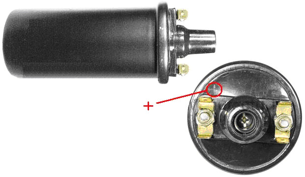 and the "+" is generally marked on the top beside the terminal with the two internal connections running to it. The circuit described so far is very close to that provided by a neon-tube driver circuit and it is certainly capable of driving a Tesla Coil. There are several different way of constructing a Tesla Coil. It is not unusual to have several spark gaps connected in a chain. This arrangement is called a "series spark gap" because the spark gaps are connected "in series" which is just a technical way of saying "connected in a row". In the chapter on aerial systems, you will see that Hermann Plauson uses that style of spark gap with the very high voltages which he gets from his powerful aerial systems. These multiple spark gaps are much quieter in operation than a single spark gap would be. One of the possible Tesla Coil designs uses a pancake coil as the "L1" coil as that gives even higher gain. The circuit is as shown here:  The connection to the pancake coil is by a moveable clamp and the two coils are tuned to resonance by careful and gradual adjustment of that connection, 10 mm at a time (after powering down and discharging the “C1” capacitor). It has been found recently, that connecting two of these (non-ballast resistor) car coils back to back with the plus and minus connections switched over, that the performance is very much improved. It has been suggested that the small self-capacitance of each coil when connected across the other coil, causes a very much higher frequency of operation, giving much sharper voltage spikes which is a very desirable situation in a circuit of this type. This arrangement might be connected like this:  The series spark gap can be constructed in various ways, including using car spark plugs, gas-discharge tubes or neon lamps. The one shown here uses nuts and bolts projecting through two strips of a stiff, non-conducting material, as that is much easier to adjust than the gaps of several spark plugs:  Tightening the bolts which compress the springs moves the bolt heads closer together and reduces all of the spark gaps. The electrical connections can be made to the end tags or to any of the intermediate wire connection straps if fewer spark gaps are required in the chain. Let me remind you again that this is not a toy and very high voltages will be produced. Also, let me stress again that if you decide to construct anything, then you do so entire on your own responsibility. This document is only provided for information purposes and must not be seen as an encouragement to build any such device nor is any guarantee given that any of the devices described in this ebook will work as described should you decide to attempt to construct a replication prototype of your own. Generally, it takes skill and patience to achieve success with any free-energy device and Don Smith's devices are some of the most difficult, especially since he admits quite freely that he does not disclose all of the details. The output capacitor marked "C1" in the circuit diagram above has to be able to handle very high voltages. There are various ways of dealing with this. Don dealt with it by getting very expensive capacitors manufactured by a specialist company. Some home-based constructors have had success using glass beer bottles filled with a salt solution. The outside of the bottles are wrapped in aluminium foil to form one of the contacts of the capacitor and bare wires are looped from deep inside each bottle on to the next one, looping from the inside of one bottle to the inside of the next one, and eventually forming the other contact of the capacitor. While that appears to work well, it is not a very convenient thing to carry around. An alternative is just to stand the bare bottles in a container which is lined with foil which forms the second contact of the capacitor. One method which has been popular in the past is to use two complete rolls of aluminium foil, sometimes called "baking foil", laying them one flat, covering it with one or more layers of plastic cling film and laying the second roll of foil on top of the plastic. The three layers are then rolled up to form the capacitor. Obviously, several of these can be connected together in parallel in order to increase the capacitance of the set. The thicker the plastic, the lower the capacitance but the higher the voltage which can be handled. The November 1999 issue of Popular Electronics suggests using 33 sheets of the thin aluminium used as a flashing material by house builders. At that time it was supplied in rolls which were ten inches (250 mm) wide, so their design uses 14" (355 mm) lengths of the aluminium. The plastic chosen to separate the plates was polythene sheet 0.062 inch (1.6 mm) thick which is also available from a builders merchants outlet. The plastic is cut to 11 inch (280 mm) by 13 inch (330 mm) and assembly is as follows:  The sandwich stack of sheets is then clamped together between two rigid timber sheets. The tighter that they are clamped, the closer the plates are to each other and the higher the capacitance. The electrical connections are made by running a bolt through the projecting ends of the plates. With two thicknesses of plastic sheet and one of aluminium, there should be room for a washer between each pair of plates at each end and that would improve the clamping and the electrical connection. An alternative is to cut a corner off each plate and position them alternatively so that almost no plate area is ineffective. As Don Smith has demonstrated in one of his video presentations, Nikola Tesla was perfectly correct when he stated that directing the discharge from a Tesla Coil on to a metal plate (or in Don's case, one of the two metal plates of a two-plate capacitor where a plastic sheet separates the plates just as shown above), produces a very powerful current flow onwards through a good earth connection. Obviously, if an electrical load is positioned between the plates and the earth connection, then the load can be powered to a high level of current, giving a very considerable power gain. Constructing High-Quality Coils. The Barker & Williamson coils used by Don in his constructions are expensive to purchase. Some years ago, in an article in a 1997 issue of the “QST” amateur radio publication, Robert H. Johns shows how similar coils can be constructed without any great difficulty. The Electrodyne Corporation research staff have stated that off-the-shelf solid tinned copper wire produces three times the magnetic field that un-tinned copper does, so perhaps that should be borne in mind when choosing the wire for constructing these coils. 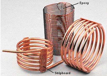 These home-made coils have excellent “Q” Quality factors, some even better than the tinned copper wire coils of Barker & Williamson because the majority of electrical flow is at the surface of the wire and copper is a better conductor of electricity than the silver tinning material. The inductance of a coil increases if the turns are close together. The capacitance of a coil decreases if the turns are spread out. A good compromise is to space the turns so that there is a gap between the turns of one wire thickness. A common construction method with Tesla Coil builders is to use nylon fishing line or plastic strimmer cord between the turns to create the gap. The method used by Mr Johns allows for even spacing without using any additional material. The key feature is to use a collapsible former and wind the coil on the former, space the turns out evenly and then clamp them in position with strips of epoxy resin, removing the former when the resin has set and cured. Mr Johns has difficulty with his epoxy being difficult to keep in place, but when mixed with the West System micro fibres, epoxy can be made any consistency and it can be applied as a stiff paste without any loss of it’s properties. The epoxy is kept from sticking to the former by placing a strip of electrical tape on each side of the former.  I suggest that the plastic pipe used as the coil former is twice the length of the coil to be wound as that allows a good degree of flexing in the former when the coil is being removed. Before the two slots are cut in the plastic pipe, a wooden spreader piece is cut and it’s ends rounded so that it is a push-fit in the pipe. This spreader piece is used to hold the sides of the cut end exactly in position when the wire is being wrapped tightly around the pipe. Two or more small holes are drilled in the pipe beside where the slots are to be cut. These holes are used to anchor the ends of the wire by passing them through the hole and bending them. Those ends have to be cut off before the finished coil is slid off the former, but they are very useful while the epoxy is being applied and hardening. The pipe slots are cut to a generous width, typically 10 mm or more. The technique is then to wedge the wooden spreader piece in the slotted end of the pipe. Then anchor the end of the solid copper wire using the first of the drilled holes. The wire, which can be bare or insulated, is then wrapped tightly around the former for the required number of turns, and the other end of the wire secured in one of the other drilled holes. It is common practice to make the turns by rotating the former. When the winding is completed, the turns can be spaced out more evenly if necessary, and then a strip of epoxy paste applied all along one side of the coil. When that has hardened, (or immediately if the epoxy paste is stiff enough), the pipe is turned over and a second epoxy strip applied to the opposite side of the coil. A strip of paxolin board or strip-board can be made part of the epoxy strip. Alternatively, an L-shaped plastic mounting bracket or a plastic mounting bolt can be embedded in the epoxy ready for the coil installation later on. When the epoxy has hardened, typically 24 hours later, the coil ends are snipped off, the spreader piece is tapped out with a dowel and the sides of the pipe pressed inwards to make it easy to slide the finished coil off the former. Larger diameter coils can be wound with small-diameter copper pipe. The coil inductance can be calculated from: Inductance in micro henrys L = d2n2 / (18d + 40l) Where: d is the coil diameter in inches measured from wire centre to wire centre n is the number of turns in the coil l is coil length in inches (1 inch = 25.4 mm) Using this equation for working out the number of turns for a given inductance in micro henrys:  Mohamed assesses Don Smith’s Devices Late in 2014, Mohamed released the following document after two years of examining and testing Don Smith’s main design. Preface This presentation is the result of more than two years of deep thinking about the resonance energy device invented by Donald Lee Smith. I was interested in this device due to the huge amount of power which it is able to provide. The device has no moving parts and is small in size. This presentation is an attempt to explain two important sources of information about the resonance energy device; they are a document and a video: The document is located here: Smith.pdf The video can be seen here: YouTube video The information contained in the document is free and open to the public. I think that it is time for such information to become widely known - free energy is free because it’s for everyone. Energy is everywhere in an unlimited quantity, ready to be taken with minimum effort, the resonance energy device described here is one of the most attractive free energy devices, it depends on a multidimensional transformer which makes possible a harmonic exchange between the positive energy reality and the unseen negative sea of energy. This is possible using a spark-gap arrangement, the energetic symmetry between the positive and negative energy oceans make it preferable to use the term ambient background energy rather than the name zero point energy. The video pointed to above, is an excellent source that can be viewed in parallel with this work, and when considered together, the reader will understand both the video and this presentation. At the start of the above video, the inventor explains the importance of the magnetic field in generating electricity. The magnetic energy upsets the background energy and that results in a separation of electrons between the two ends of a coil, this separation of electrons is a source of electric power. The resonance energy device is based on a very important idea, namely, that magnetism and electricity are two sides of a single entity! Matter and energy are two aspects of the same thing as Oliver Heaviside expressed in his famous energy equation E = MC2. The electrical equivalent of this in our Resonance Energy Device is: In this presentation, we will learn together how the device works but before any attempt to use this information, please pay attention to the following caution:  You need to read this document again and again to understand the power behind this device; this device is a power producer! You are near a power production factory but in a small size, this special coil only needs voltage and when we oscillate that voltage, the voltage turns into real current ‼ This means that even a short-circuit isn’t permitted in the collection system if you plan to use HV capacitors. This is not the place for amateurs, please do not attempt to implements or use the information shown here unless you are experienced and skilled. Neither the publisher nor the author makes any representations as for the completeness or the accuracy of the information contained here and disclaims any liability for damages or injuries resulting from your actions. Algeria, August 2014 hopehope3012 (at) gmail (dot)com Let’s examine how a magnetic field generates a voltage in an ordinary coil and why our coils lack the energy key that Donald Smith has found  When a magnetic field penetrates a coil, the induced rotating electric field generates additive elementary voltages along the coil. Every turn in the coil receives the same voltage, we extract the power along the length of the coil, but we miss the power available in the area inside the coil !! To understand this, let’s examine the induced electric field:  If we examine Fig.2, which represents a single turn of the coil shown in Fig.1, we see that the magnetic field penetrates all of the area inside that ring. This magnetic field will be transformed to a voltage because it will drive a rotating electric field, this field is able to induce a voltage and this induced voltage will cause the current to flow due to the different of voltage between the two points A and B in Fig.1. The important, generally forgotten thing about the induced electric field, is its availability inside our coil as shown in Fig.3:  The induced electric field exists independent of the conducting loop. In other words, an induced electric field permeates all of the space within the region of the changing magnetic field, as indicated by the red field lines in Fig 3. What about this field? It is wasted power. It is wasted power at point A, as well as all of the distance between the two points A and B. If we want to achieve power amplification we have to combine the magnetic field with the induced electric field in such a way as to conserve the non-conservative electric field! The induced rotating electric field will remain non-conservative but we could play with the induced voltage created by that field using a Tesla Bi-filar Coil (“TBC”). We need to extend the capacitive side of a Tesla bi-filar coil in order to benefit from the induced E field to a reasonable degree, if we try to use a flat TBC we will face the same problem in our solenoid coils where we concentrate between two points. The heart of the Resonance Energy device is based on an extended Tesla bi-filar coil (Fig.4)  During my search for the specification of Tesla bi-filar coil I wasn’t able to find a lot of information such as the resonance frequency of this special coil as if it has been forgotten, although it has been known since 1894! I felt it’s without advantage; fortunately at that time I successfully built a new type of asymmetrical capacitor that has four plates rather than three plates, I was able to replicate my source voltage, I gave it the name C1/C2 system, when I fed C1 with high voltage I was able to take the voltage from C2 without direct contact, the device is based on the electric field interaction between C1 and C2. The C1/C2 system opened my mind to the possibility of charging a capacitor without the need of direct contact; with the device. I began thinking in a different way, wondering how I could combine the two side of electricity in just one device. The device shown in Fig.4 can be simplified as shown in Fig.5:  The magnetic side is the path from A to B, it is the path which the current will follow, and then the magnetic energy will be formed and concentrated inside our coil, the magnetic side is the hidden side of electricity because we can't conserve this state for a long time as we do in the capacitors. This side is directly related to the ambient background energy or zero point energy. (Later we will see why Donald Smith prefers the name of ambient background energy as opposed to ZPE) To make things easier we could take the permanent magnet as an example, the permanent magnet appears to create the magnetic field all the time without requiring us to provide any visible power for which we have to pay. The electric side of this amazing coil is the most difficult thing to understand. The capacitor in our extended Tesla bi-filar coil is just one point! It’s the point “X” but from a static perspective, we say that it is between points C and D. The path from C to D is the way to conserve the direction of current needed to build the coil and ensure the maximum voltage is generated between the two plates of the capacitor. This capacitor is a dynamic capacitor and not a static capacitor. In this capacitor the displacement current is absent... because it gathers the two polarities of electricity in one device. The magnetic side is the current side where the current starts from point A and flows to point B. The electric side is the point at which the maximum voltage between the two plates exists. I think that this is the most difficult point to understand in the Tesla Bi-filar Coil, because we see it as just a coil and not a coil with a built-in capacitor! Back to 1894 and take a look at what Mr. Nikola Tesla said about his bi-filar coil: My present invention has for its object to avoid the employment of condensers which are expensive, cumbersome and difficult to maintain in perfect condition, and to so construct the coils themselves as to accomplish the same ultimate object. Let us start by analysing how the extended Tesla bi-filar coil works. Imagine that the following drawing is a charged, extended Tesla coil with the positive and negative parts, shown as red and black plates respectively  When we connect these two plates by their points C and D, an electric current will flow from point A to point B as shown by the red arrows. When the induced electric field finds a coil which is wound counter-clockwise (“CCW”) – the red plate - versus another coil wound clockwise (“CW”) – the black plate - this electric field will generate an induced voltage which will tend to recharge the capacitor again! The rotating electric field will start to build an induced electric voltage from point B which will be 0V in this case because the induced electric fields rotate in a clockwise direction. When the magnetic field increases, the electric current will flow counter-clockwise and so the direction of the magnetic field will be out the screen as indicated in Fig.6. In this case we achieve a cost-free voltage difference between adjacent plates. This situation attracts electrons which were not previously available, to become incorporated and produce a very large net gain in potential, this gain is real !! The induced rotating electric field flows in closed loops but this design causes it to build a voltage difference between adjacent plates. This fact prevents the voltage difference between the adjacent plates from dropping and it makes the replication of electric power with radio frequency a practical operation. Because of this, we can understand why resonance can't produce the power but it replicates the power with radio frequency and this is the secret of the huge power which this device is able to give with the equation which Don Smith gave us:   The induced rotating electric field will build induced elementary voltages; B is the starting point for that field, so it will have 0V but when we arrive at point D it will have V volts, which same voltage will be available at point C. The induced rotating electric field will continue it’s rotation producing a value of 2V at point A !! (Fig.7). A question arises: where is the capacitor if C and D both have the same voltage? The capacitor in our extended Tesla bi-filar coil (TBC) is a dynamic capacitor, it will be formed only when the coil oscillates. When that happens, the induced electric field will give C and D the same value of voltage but every adjacent turn will receive the same difference of voltage needed for attracting ambient electrons which weren’t originally in the system but now are incorporated in large numbers, providing the excess power. This capacitor appears due to the junction CD, and from a dynamic point of view, it is the point X. This device treats the magnetism and electricity as if they are the same thing. When this happens both sides help the other side. The displacement current is absent here because it appears when we separate electricity and magnetism. When we do that, we fill the gap by introducing something isn’t real. The displacement current does not exist !! When you move a permanent magnet in the air, an induced electric field will appear regardless of the presence of a coil. The electricity is there, it comes from the background energy and returns to its background level, both electricity and magnetism have the same origin, the magnetism is the energy side (magnetic field), the electricity is the physical side (electrons). The physical side appears when we place a conducting coil in an area where there is a changing magnetic field. The magnetic field causes the electrons to rotate CCW and produce voltage and rotate CW and produce current, voltage electrons appear to be more negative because they are more active, current electrons appear to be less negative. We seek the number of electrons separated by the changing magnetic field. The current (I) is the energy killer because it absorbs the power of the voltage electrons! In this system, the magnetic field penetrates inside a special capacitor coil where both sides of electric power are found in a unified state. We discussed the phase when the capacitor discharges across itself, and now it is time to see how the coil will charge the capacitor with a reversed polarity. It’s important to review the resonance in a normal L/C circuit to understand the work of the extended TBC. Imagine that you have a charged capacitor, when connected to a coil a current starts to flow, when the current reaches its maximum value, this means that the capacitor was totally discharged, the magnetic field will have the greater value and start to decrease and induce a voltage which will charge the capacitor again with the opposite polarity. The same will happen in our extended TBC, when the magnetic field reaches its maximum value it will then decrease and induce a voltage which will charge the capacitor again, the complexity here is to understand the positions of coil and capacitor.  In a dynamic perspective the coil sees the capacitor in the X position, the coil situated between A and B, comparing this to what happens in a normal L/C circuit at this phase the coil has to drive a current outside its region, the outside region between A and B has to be position X. when the magnetic field induces a current to recharge the capacitor between C and D, the induced electric field will do this job because it will change the direction of rotation to be CCW (Fig.8), and this behaviour will tend to keep the current at a high value while the voltage increases! The position of the capacitor in this device has to be the position of a spark gap. A spark gap in this position will improve the performance dramatically and amplify the power gain. The Resonance Energy device works with radio speeds above 20 kHz. The ambient background electrons are usually found in a dormant or inactive state and this makes the drawing-in of ambient electrons a difficult operation. For this reason, we need an earth connection to improve the performance of this system, later in the video, Don Smith talks about something new, the earth connection isn’t needed because there is something called air grounding.  To activate air electrons effectively we need another source of power, actually this source of power exists as a negative energy but before we go further, we have to see the symmetry between the electric and magnetic sides. When we start from A to C we have half coil-capacitor while from D to B we have capacitor-half coil. To understand how our extended TBC receives negative energy, it is better to see the way in which the device oscillates. There are two methods of feeding this coil: The direct method Here we have to know the resonant frequency of this coil or alternatively, we need to have the resonant frequency covered by our feeding circuit. This method is the best because we don’t need lots of power, because when we achieve resonance our extended TBC will have a very high impedance, and so, a maximum voltage will be available between A and B, and fewer turns will be needed in the reactant coil L2. The indirect method Here we don’t have to know the resonant frequency, if we feed this coil from A and B the capacitor will charge. The spark gap has a very high resistance and it will not fire until there is a voltage difference between points C and D, at that moment a spark will occur, and when that happens, the resistance of the spark gap drops from a very high value to very low value and that short-circuits any power coming from the power source until the natural coil resonance finishes! When the capacitor is fully charged, the maximum voltage appears between points A and B which is the coil side, when the spark occurs the capacitor will transform into a coil which has a capacitor built into it! This operation provides the natural resonance needed without causing any problems. Caution! When we feed this coil from point A to point B and then disconnect it from the power source, you would then expect to discharge it by short-circuiting point C to point D (usually from the location of spark gap). If you do this and then touch the coil you will definitely receive a substantial high voltage shock! Even if you see the spark, the spark will not discharge this capacitor immediately but it will cause the coil to oscillate again and recharge itself. This device isn’t a simple capacitor because when you short-circuit the spark gap it will transform the electrical energy into electromagnetic energy capable of recharging the capacitor again. If you try to short-circuit points A and B in an attempt to discharge the extended TBC, then these two points will transform into electric points (due to the symmetry). From a static perspective, the capacitor can take an AB position as well! The solution is to short circuit C to D permanently and then short circuit A to B at the same time. As I mentioned before, there is a need for extra energy in order to activate air electrons effectively. In reality, this is not exactly what will happen as the arrangement is complicated. The negative energy enters this device in an unusual way. The extended Tesla Bi-filar Coil will supply reactive energy in enormous amounts because there are common characteristics between reactive energy and negative energy. Reactive power is a kind of electrical power, measured in volts-amps-reactive (“vars”) which cannot do work in its present form. For sinusoidal waveforms, the formula for reactive power is The reactor coil in our system is a shortened version of a normal parallel L/C circuit. The output energy received in the reactant coil has to be a reactive energy because of the presence a coil in parallel with a capacitor. The phase angle between current and voltage is 90 degrees, and so, the active energy in this case will be zero. The system acts like a negative resistor, it’s a non-dissipative system because it’s an energy absorbing system:  The reactive energy in this system is an advantage. The energy is ordered and so we can easily achieve super-conductivity at room temperature! As shown in Fig.10, active energy is a chaotic energy and so it is not easy to get rid of resistance. The important point where we need to focus our attention is where the voltage has a maximum value the current will be totally absent. Negative energy is a kind of electric power obtained when sparking (on-off) from a high voltage direct current (Fig.11).  This is why we need a high-voltage diode in our power supply circuit. The resonance in a normal parallel L/C circuit does not require this. If we connect a spark-gap between point C and point D, then the negative energy will be drawn into our system with the same speed as positive energy! The symmetry between the magnetic and electric sides in our positive energy reality will open the correct door for the undetectable negative energy reality! Initially, when the capacitor starts to discharge, the current increases but the induced rotating electric field will tend to keep the voltage at a high value. The capacitor discharge through the spark-gap (which requires a large amount of voltage), the current flow does not start immediately. Initially, the current increases but the spark does not occur. This pushes the voltage up higher (behaviour which is known in parallel L/C circuits), then the current increases to a high value very quickly, while the voltage is drawn down to a level which cannot sustain the spark. When the capacitor is totally discharged the current flow through the spark-gap is at its maximum value. Consequently, the extended Tesla Bi-filar Coil produces a square wave rather than the expected sine-wave which is produced by an ordinary parallel LC circuit. The square wave produced when the spark occurs, contains waves of all frequencies and so, even if the time during the spark is short, there will still be thousands of oscillations in that time. I know that it is not easy to visualise this, but it is what actually happens. This special genius design solves the most difficult problems in cold electricity, due to it's reversed behaviour compared to hot electricity. Cold electricity prefers to flow along materials which we consider to be insulators while hot electricity prefers to flow along materials which we consider to be conductors. According Tom Bearden, with negative electricity the capacitor performs in the way that a coil does with hot electricity, and the coil will perform like a hot electricity capacitor (Fig.12)  the above illustration is an attempt to understand how cold electricity work but it's better to take a look at Floyd sweet explanation of his VTA device in the Appendix (page A-1209) : it is important to note that so long as positive energy is present in a positively-flowing time regime, then unity and over-unity power gains are not possible. The summation of the losses due to resistance, impedance, friction, magnetic hysteresis, eddy currents and windage losses of rotating machinery will always reduce overall efficiency below unity for a closed system. The laws of conservation of energy always apply to all systems. However, the induced motional E-field changes the system upon which those laws need to be applied. Since the vacuum triode operates in more than four dimensions and provides a link between the multi-dimensional reality of the quantum state and the Dirac Sea, we are now dealing with an open-ended system and not the "closed system" within which all conservation and thermodynamic laws were developed. To achieve unity, the summation of all magnetic and ohmic losses must equal zero. To achieve this state, negative energy and negative time need to be created. When this is achieved, all ohmic resistance becomes zero and all energy then flows along the outside of conductors in the form of a special space field. The above explanation describes the VTA device but also demonstrates the work of the Resonance Energy device of Don Smith !! The correct model of capacitor is the extended Tesla Bi-filar Coil because it provides a link between the multi-dimensional reality of the quantum state and the Dirac Sea of negative energy. From a positive energy perspective, AB describes the coil while CD describes the capacitor, but the coil will transform into capacitor AB in the region of negative energy; and in the same area the capacitor will transform into the coil !! How can we explain this physically!? The energy equation and Dirac’s equation call for both positive and negative energy. Thus they are symmetrical with respect to energy, as are the forces of physics positive repulsive forces increase positive energy, while negative attractive forces increase negative energy. According to the modern kinetic theory of mass-energy, negative energy would merely be a vibration of charges at right angles to our ordinary dimensions in an “imaginary” direction. (Fig.13).  To understand Fig.13 correctly, we need to remember that we are confined by our positive energy reality; in our extended Tesla Bi-filar Coil we need the negative energy in our positive side, the spark gap in CD position is the flexible place for both positive and negative energy to be combined. Tom Bearden has an important book entitled “Energy from the Vacuum”. The following text is on page 236 where he explains the specification of a true negative resistor: The true negative resistor is an open dissipative system a priori, and equilibrium thermodynamics therefore does not apply. Instead, the thermodynamics of open systems far from equilibrium applies. The negative resistor freely receives energy from outside the system (from the environment), and “dissipates” it in interception and collection actions inside the system, to freely increase the available potential energy in the system. In circuits, the main characteristic of a negative resistor is that the environment freely furnishes some excess energy to (i) power the load, and/or (ii) move the current back against the voltage, particularly when shunted across the back emf region of the source dipole. The operator does not have to furnish this excess energy dissipated to propel the current backwards or dissipated to power the load! The true negative resistor in our system is the blue extended TBC where negative energy moves the current back against the voltage; this power will charge the coil electrically if it’s acting as a capacitor! The electric current in the negative energy region (past light cone) works in a reverse manner compared to the electric current in positive energy region (future light cone), the symmetry between the magnetic energetic side and the physical electrical side will curve space for the negative energy power to enter our device through our flexible spark-gap zone which represent a one dimensional capacitor X, the negative energy which can be represented by attraction forces will find its way through the spark-gap to increase the electric energy through AB, the system will continue its divergence and the clockwise rotation of the negative energy current will increase the counter clockwise rotation of the hot electric current (potential energy), this tends to amplify the power between point A and point B which represents the voltage gained by this virtual current! We are examining the first instant when the capacitor discharges across itself (transform into coil), the curved AB space will transform into one point in the negative energy sea which is the capacitor in our imaginary extended TBC. Similarly, when the magnetic field collapses and charges the capacitor across CD, the magnetic field returns to its background level, the space-time continuum is reversed by the fields which are produced in the presence of excited coherent space flux. These quanta have been attracted from, and ultimately extracted from, the virtual vacuum, the infinitely inexhaustible Diac Sea (from Floyd Sweet papers in the Appendix). Like charges have repulsion behaviour on the positive energy side, while they attract each other in the negative energy region. This information is essential for an understanding of the nature of the negative energy sea. When the turn comes (second time period) for our capacitor to be charged again with opposite polarity, the system will diverge toward negative energy space to close the loop in that space !! The current passes from C to D to charge the capacitor but in the virtual dimension it starts from D and finishes in C. This power will charge the capacitor magnetically if it's a coil. As you see there is positive real energy and undetectable negative real energy. I think that Don Smith preferred the name ambient background energy as opposed to Zero Point Energy because there are two regions from which we can take power, namely, over ambient background energy and below ambient background energy. At this point, we can understand why cold electricity prefers insulators rather than conductors. This kind of power is capable of running in an imaginary dimension parallel and reversed relative to our ordinary, familiar dimension. But… according to Floyd Sweet; when run in parallel with positive energy however, cancellation (annihilation) of opposing power types occurs. This has been fully tested in the laboratory. This applies to the chaotic positive energy flowing regime time when voltage electrons (ccw rotation) and current electrons (cw rotation) run together at the same time, our Reactive Energy resonance system works in harmony with negative energy, our previous study allows us to draw us some important conclusions: For the first time period, we have (C discharging across L); + energy increase magnetic energy ---- I - energy increase electric energy ---- V For the second time period we have (L charging C); + energy increase electric energy ---- V - energy increase magnetic energy ---- I since magnetic energy is the current and electrical energy is the voltage and because they are out of phase (reactive energy), positive energy will work in harmony with negative energy and no cancellation will appear. Our extended TBC is a very important device not only because it can supply unlimited electric power but it give us an exceptional opportunity to understand the way that energy flows inside our universe! When the device oscillates it produces cold electricity and hot electricity, this means that the device is able to relate to both positive and negative energy. The flow of energy has two directions; from positive to negative and vice versa. Let’s think about the physical way in which things work. In this analysis I’m trying to explain some deep physical aspects about positive and negative energy. As illustrated in Fig.12 and Fig’13, it is important to consider energy flow in relation to time. These two pictures just represent my thoughts and understanding of the subject. Cold electricity has the ability to produce an electric response when it interacts with metal surfaces. This can also be seen in the Casimir Effect where two non-magnetic metal plates, which are not carrying an electrostatic charge, are suspended very close to each other. The plates do not hang straight down but move towards each other. Cold electricity has the ability to produce an electric response when contacting metal surfaces because it’s able to ionise empty space. In our extended TBC, when the spark occurs, we are actually colliding the space-time field through one point (the spark-gap). The space-time field is, in my opinion, the space where negative and positive energy exist together, they exist together but cancel each other out due to a constant ratio. If we take a mass with a gravity field around it, and we move the mass and create a mass current, a new field is also created. It is a different kind of gravity field with no source and no sink, when the speed of the mass increases, then the created gravity field increases also. If the mass reaches the speed of light, then this means that it has the value E = mC2 as a positive energy. mC2 is the maximum value exchange between positive and negative energy admissible by zero point fluctuation (ZPF) for that mass to exist the way it does in its time-space field, the mass has two options to reach the speed of light: 1. It will transform into exotic matter. 2. It will break the time-space structure. The only places which provide these two conditions are black holes. Black holes exist in the centre of galaxies which provide the rotational energetic symmetry between the mass and gravity field - see Fig.14, Fig.15 and Fig.16.    For a spiral galaxy to maintain its shape with cosmic dimensions (the diameter of galaxy may exceed 100,000 light years) there is a need for a negative energy to be the underlying energy for space-time throughout all of that galaxy. That negative energy has to transport virtual particle instantly! The transformed physical matter (including space-time!) provided by black holes furnishes an excess of positive energy in the galaxy, providing stability and symmetry. Black holes are not a fracture in space-time but they are essential. The above explanation will help to clear the way for a better understanding of the nature of electric energy. This explains why a sharp positive-going DC electric pulse interacts with negative energy to produce cold electricity which is an instant response from the negative energy sea. This response does not start from the spark-gap, but it ends in it! The negative energy will rotate to finish in the spark gap, this will squeeze the space-time to provide excited coherent virtual particles which in turn produce electronic responses when contacting a metal surface. From my point of view, the electronic responses created in metal surfaces have a magnetic angular momentum. Cold electricity is able to charge a capacitor to a much higher voltage than the capacitor’s voltage rating, even if the capacitor’s rated voltage is low. The question which springs to mind is; do electric fields inside a capacitor charged with cold electricity really exist? If the answer is yes, then why isn’t the capacitor destroyed? In my opinion, it is because the electronic responses caused by cold electricity have magnetic angular momentum instead of electric field lines. I suggest that the presence of magnetic field lines between the positive and negative plates of a capacitor charged with cold electricity are actually as shown in Fig.17.  When the spark gap impacts on space-time (that is, when the spark occurs) the response from the negative energy sea looks as if it should neutralise the excititation created in the positive energy side (Fig.18). We can’t detect the movement of negative energy, and so we only see the impact which it has in our positive energy reality.  The small red ball in the above drawing, is the spark gap which is the door for negative energy to enter our positive energy reality; the negative energy sea will react both before and after the spark occurs. Referring back to Fig.14, before the spark-gap fires the negative energy will rotate starting from the spark-gap to neutralise the excitation created in the positive energy side (Fig.19a) and when the spark-gap finishes firing, the negative energy will end in the position of the spark gap (Fig.19b).  The Bloch wall area in an ordinary permanent magnet, is the area of electron separation. Let’s see how this happens in our extended Tesla Bi-filar Coil. During the first time period, when the capacitor starts discharging across itself to become a parallel L/C circuit, point A will provide a maximum voltage while point B is the maximum current. The current flow starts from point A and finishes at point B. The system is now producing magnetic energy and because of the magnetic field increase, the electrons will start from point B and flow to point A which causes clockwise rotation to neutralise the counter clockwise spin of the voltage electrons, and cold electricity will charge the coil electrically if it is acting as a capacitor, and it will push the current to go back against the voltage by providing a magnetic angular momentum (the clockwise rotation shown in Fig.19a) at point X the result is to turn back the voltage electrons, causing strong initial potential electrical energy which increases the electrical energy. Current in cold electricity is the equivalent of voltage in hot electricity. The Bloch wall is the place where negative energy interacts with our E-TBC, in other words when the spark-gap fires, the current will not start immediately because the negative energy will supply a virtual current by providing a CW rotation in the Bloch wall area X. This virtual current is a compensator of the real current but it will not absorb the power from the voltage electrons which increase the available potential electrical energy. All this happens before the real current increases to provide the magnetic energy. Caution: Please be aware that high voltage capacitors have dielectric recovery which stores the electric field for a long time. High voltage capacitors need 5 minutes or more to discharge completely. Energy is everywhere and in enormous amounts ready to be taken for free. When we do that, we do not reduce the available power because the universe is full of energy, the energy in our universe is the source, physical matter is the energy in a visible form and the energy is in invisible matter form. The presence of the negative energy sea beside our positive energy reality, raises an important question, namely, why they are separated when they could be united? They are separated to let our universe exist in the way that it does. Negative energy serves our existence because it's designed to be the under background energy level for our foreground positive energy reality. Our existence is a thin part between those two energetic oceans. Negative energy is extremely active until the point when it appear to be nothing! We now need to explain another important behaviour of our extended Tesla bifilar coil, namely, it’s super conductivity at room temperature. One of the puzzles in this device is its capability to equal the voltage with the current. The wire of the coil AB can receive ambient electrons because it’s the surface for the capacitor CD; let’s examine this surface in Fig.20:  When the capacitor discharges across itself to become a parallel L/C circuit, the induced rotating electric field (with the help of negative energy) creates a difference of voltage between adjacent plates, this voltage according the Gauss law causes new electrons to be present in the system.   When ambient electrons enter our system (Fig.21), they increase the power gain across the Y axis (Fig.20). When the current flows inside the extended TBC, parallel currents will be added while parallel voltage will be the same in the Y axis, while in the X axis serial voltage will be added while serial currents will be the same!! On the X-axis: sum (V) equals (I) This system treats the voltages and currents in the same way, the voltages and the currents are physically equal. When this happens the device squares the electromagnetic flux and becomes a near-unity system in every process which will replicate the electric power according to the working frequency. This is a near-unity system due to the super conductivity at room temperature where the electrons don’t face the usual reduction encountered in an ordinary parallel L/C circuit. A normal L/C circuit cannot produce the super conductivity at room temperature because the exchange between the electric power and the magnetic power must lower one of them in each process. In our extended TBC they are combined in such a way so as to amplify the power in every process, and so the total available electrical energy in each cycle is twice the power available in a charged capacitor which can be seen from the following relationship: (consider the similarity between the magnetic and electrical energy in a resonating parallel L/C circuit) Here, I need to explain the importance of the reactive electric power in the Resonance Energy device, in an alternating electric system where the voltage and current go up and down at the same time (Fig.10). Only active, real power is transmitted and when there is a time shift between current and voltage both reactive and active power are transmitted. When this time shift is 90 degrees (π/2 degrees) the transmitted real power will be zero as discussed above. This does not mean that there is no power, but it does mean that we cannot use this power in this alternating form, we have to transform it into Direct Current so that both current and voltage are united. Reactive power looks like a skipping rope (Fig.22):  Imagine the voltage to be the rope and the children's bodies are the current. Reactive power looks like a skipping rope, the active power will not let the kids’ bodies move correctly. Reactive power is an essential part of the Resonance Energy device, and a skipping rope is good example which shows how kids go up and down without any problem. This sort of movement exists in our device. The separation between voltage and current in the Resonance Energy device is crucial for producing and cloning electric power at radio frequency speed. A proper method of collecting and converting the huge available electric energy is needed. The example given in Fig.22 is important when planning to collect and convert the available electric power. If we simply use a step-down transformer it is highly likely that we will alter the current which will reduce the gained power. With reactive energy, when the voltage is high the current is low. A step-down transformer will lower the voltage but it can’t amplify the current as expected! In a normal transformer we amplify the current depending on the available active power (V x I):  Physically (Fig.23) the electromagnetic flux inside the transformer has two components, the electrical component V and the magnetic component I, for successful transfer of electric power from the primary to the secondary, both of them are needed at the same time. In our case, when V is high the product (V x I) is low due to the time shift, even if the available power could achieve megawatts! Another factor which we have to take into consideration, is the high-speed needed to replicate the power, using a transformer to lower the voltage imposes the need for a special transformer core which is able to respond at radio frequencies. These facts have to be taken seriously if we want to collect the available energy effectively. 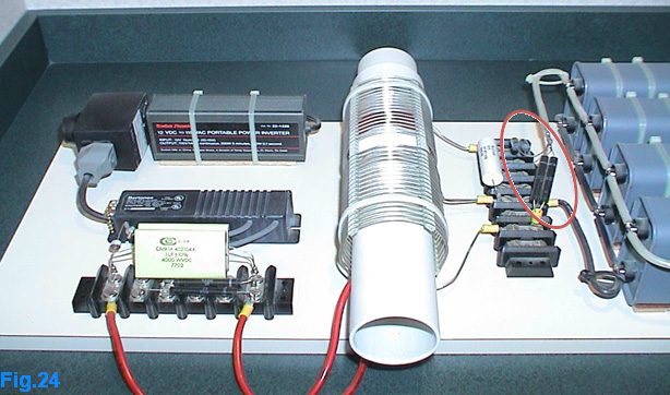 Personally, I prefer to improve on the use of high-voltage diodes as shown in Fig.24. It is better to use a diode bridge constructed with fast recovery high-voltage diodes. Fast recovery diodes have the ability to return to their blocking state very quickly, making it possible for the other half-oscillation to be accumulated in the high-voltage capacitors, each cycle (up and down in Fig.25) will give power similar to the power available in a charged capacitor given by the following equation ½ C V2  The amazing, energetic behaviour of the extended Tesla Bi-filar Coil make it totally different from an ordinary parallel L/C circuit. Our extended TBC gives twice the frequency of an equivalent parallel L/C circuit. This means that if you form the same inductance with the same capacitance in an ordinary parallel L/C circuit, then that will produce only half the frequency that the same combination produces with an extended Tesla bifilar coil form! I have not been able to verify this because I don’t have an oscilloscope or a frequency meter. That, of course, is no excuse for not thinking about how the device will act, so the following analysis is an attempt to imagine the energy equation given by Mr. Donald Smith as: To simplify things, let us analyse only the voltage. When the capacitor discharges across itself to become a complete parallel LC circuit, at that instant, the magnetic field reaches it’s maximum value. What makes this system different, is the induced rotating electric field. This field will instantly charge the capacitor with the opposite polarity before the induced current resulting from the collapsing magnetic field can do it. As we learned before, this is the key to energy amplification. Resonance is the key for energy multiplication, our extended TBC acts like one device, so the passage from the positive cycle to the negative cycle takes no time. In other words, the device has the ability to change it’s direction of charge instantly. The yellow zone in Fig.26 is absent (compared to a normal parallel L/C circuit), when the energy cycles up and down (Fig.25) the device gives twice the power available in the capacitive side of the extended TBC.  The power is each cycle will be given by: Since the frequency will affect both the voltage and the current we will examine the equation number 1 as follows: CV x V, the product CV is the quantity of charge available in a charged capacitor, if we divide it by 1 second this will give us the current since Q/T is the current in one second. Let us suppose that the frequency is 3 Hz.  From Fig.27 we can see that the total available power is proportional to 9 which is the square of the given frequency. Each cycle has the power of C V2, the number of cycles in one second gives us the frequency; the frequency will replicate CV which is the current and this will give us CV x F and replicate the voltage by the product V x F, this analysis is the best explanation of why the voltage equals the current in this system, because CV x F is the available current and V x F is the available voltage! This seems strange; how could the product V x F be the available voltage since the result is very high since we are working with radio frequencies above 20 KHz? The example given in Fig.23 will help us understand this. The energy formula gives the available DC power when converted from its alternating state; the electromagnetic flux will be squared causing amplification of both current and voltage. In each second, the available power is CV x F x V x F, the power obtained depends on the number of turns in coil L2, and the limiting factor is the product V x F which is a very high number in practical systems. Below this factor, the current is very high being the product CV x F !! This explains why a megawatt sized unit can fit quite easily on a breakfast table and it explains why this device is able to give any required level of energy. The energetic formula of our extended TBC can now be written as follows: This equation gives the available power in watts when converted into high-voltage Direct Current. When the device oscillates the power obtained is pure reactive energy, Volt-Ampere-Reactive (VAR) is present while active electric power (W) is absent in this dynamic state, Fig.28:  In practical terms, the extended TBC is just a high-voltage capacitor which has the ability to let the current penetrate inside itself, so it has both magnetic and electric specifications. Practical section A free-energy device is something which is fascinating, being hasty in wanting to build and test one is common, but that is not good. High-voltage with high current isn’t a game !, your first mistake may well be your last. If you decide to build this device in your house it is a good idea to use locks and keys and sticking a high-voltage warning symbol on the device is a sensible action. I am not encouraging you to actually construct the device described here; the above theoretical information provided is the most important section. When the device is fully understood, then taking care when near it will be automatic. This device is a very special Tesla coil, when increasing the voltage in a normal transformer the current drops, but here the current increases in the same manner as the voltage does! This device has current equal to the voltage. Resonance will impact both the voltage and the current. The special geometrical design of the extended Tesla Bi-filar Coil, including the flexible position of the spark-gap, produces the needed rotational energetic symmetry between positive and negative energy. As we have already seen, the spark gap opens the door for a massive inflow of electrical energy to be present. I personally got shocked indirectly from the L2 coil and I certify the risk of this device. For construction, the first thing we need is a source of high-voltage. The device can be fed using two different methods as described here. The first is the direct method where the high-voltage power source has the same frequency as the natural resonant frequency of the extended Tesla Bi-filar Coil. The second method is the indirect method; where there is no need to know the frequency of the reactor (active) coil. The high-voltage power source is needed to feed the extended TBC which is the reactor coil (active coil), Fig.29 shows an easy to build oscillator:  It’s better to use a flyback transformer which has a high-voltage diode built into it. Flyback transformers are readily available and cheap. The above circuit diagram is for a flyback transformer, where a high-voltage power source enter our reactor coil via points A and B (Fig.30):  Initially, the capacitor charges up to the value needed by the spark-gap. When the voltage across the electrodes of the spark-gap reaches a high enough value, a spark occurs causing the resistance of the spark-gap to jump from a very high value to a very small value, short-circuiting any power coming from the power source until the natural resonance finishes. The capacitor transforms into a complete coil which has its capacitor built into it. The natural resonance of the TBC is assured when using this method, but it does have some disadvantages. The frequency produced by power supply/spark-gap combination has to be high enough to allow more power to be produced and this calls for a powerful power source. On the other hand, the voltage between the reactor coil AB will be limited by the distance between the electrodes of the spark-gap. This imposes the need for a large number of turns in the L2 coil. The output current obtained is directly related to the available voltage between the capacitor plates which form the device between A and B. We need to bear in mind that the capacitor incorporated inside our extended TBC operates in a dynamic fashion where no displacement current exists. The direct method of feeding the reactor coil with its own exact natural frequency is the best way to get the most available power, but this creates a real problem as it is not at all easy to find a high-voltage power supply adjustable over the range of frequencies which we want, especially frequencies above 200 KHz. We may require our extended TBC to work above 200 KHz, and for that, we may need impedance-matching capacitors (Fig.31).  The two yellow capacitors seen above are for impedance matching since the working frequency in Don Smith’s device was very high, requiring a neon-tube driver to supply it.  Impedance matching is simply the process of making one impedance look like another; in our situation it is necessary to match the load impedance to the source. For example, if the extended TBC resonates at 2.4 MHz, (this is the load), and the neon-tube driver operates at 35.1 KHz (this is the source) we need to add parallel capacitors to our extended TBC in order to make it resonate at 35.1 KHz. In practice, you need to short-circuit the points C and D and measure the inductance of the E-TBC (L2 has to be in place for this measurement). After that, remove the short-circuit and measure the capacitance of the E-TBC. This gives you two values “C” and “L”. The resonance of the Extended –Tesla Bi-filar Coil is given by: When you add a capacitor for impedance matching to the extended TBC, the resonance frequency will decrease with the following relationship I believe that we can use the above equation to calculate the value of c* which needs to be added in order to achieve resonance. From equation (b) we could write  Using equation (c), we will be able to calculate the needed capacitor for impedance matching; the value obtained is in Farads, and that equation the frequency is in Hz and the inductance in Henries. When you have the correct C* value and you power your device up (Fig.33), resonance will not be achieved instantly because the spark gap forms the full L/C parallel circuit only when it fires!!  The first thing which happens is the charging of capacitor C*, after that the capacitor “C” of the extended TBC will be charged until it reaches the voltage needed to make the spark-gap fire. When that happens, the spark-gap has a very low resistance value, making the E-TBC fully formed. At this point, the incoming electric energy from the high-voltage power supply will find a load whose impedance matches it’s resonant frequency. This, in turn, produces the maximum possible voltage across inductance L of the E-TBC. Further, the resulting electromagnetic field will increase cycle by cycle causing the device to resonate fully after a very short time.  Constructing the extended TBC The extended Tesla Bi-filar Coil is just a high-voltage capacitor which has a magnetic behaviour. So, it is both a capacitor and coil at the same time. Constructing this device is relatively simple. You need two lengths of aluminium foil, each 1.2 meters long (later I will explain the possibilities of modifying the characteristics of an extended TBC). Because it is a capacitor, you need 3 pieces of polyethylene sheet, each 1.3 meters long. To construct a high voltage capacitor usually you need 2 pieces of polyethylene sheet but it's better to use 3 pieces since we are working with a high voltage (Fig.35), this will depend on your skills in constructing a high voltage capacitor. You need welding rods to insure the electrical conductivity of the aluminium foils, Fig.36 indicates how to do that. Actually the best length and width of aluminium foil need some experimentation; you have to establish the positions of the magnetic and electrical points (Fig.37). A and B are the magnetic points (coil) while C and D are the electric points (capacitor).    The E-TBC need a coil former for it to be wound on it (Figure 38) 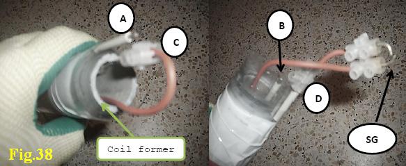 The following photo shows the dimensions used in the prototype (Fig.39)  Internal arcing is a common problem with high-voltage capacitors (Fig.40)  The best combination between the length and the width of an extended TBC has a major influence on the electric energy obtained at the L2 coil (the reactant coil). For example, the electric arcing experienced at the L2 coil using the E-TBC shown in Fig.41, was very weak, the length shown by the black arrow is very much greater than the width (orange arrow), this give a weak magnetic flux due to the small coil inductance, the coil inductance is very important because it will transform the replicated power into electromagnetic flux. 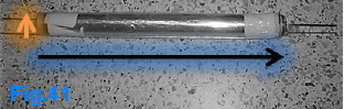 The reactant coil (L2): 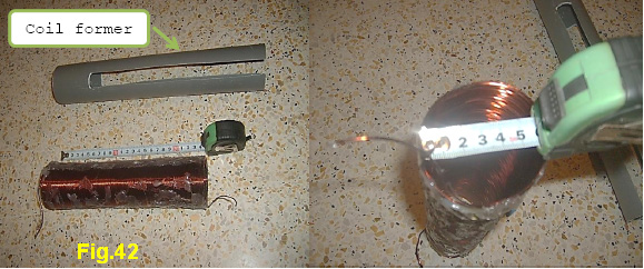 The coil length is about 25cm as shown in Figure 42, the diameter is 6 cm, and the thickness of the wire is 1.18 mm (AWG #17 or swg 18) and the number of turns is about 200. Fig.43 shows some nice sparks from L2 coil: 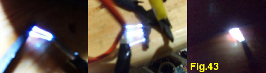 The spark shown above is very strong but it can't burn through thin paper! This proves that the electric energy obtained is reactive, and so it can't do work as it is. Converting a high-voltage reactive electric power into Direct Current isn't easy to achieve. Working with a voltage over 10KV is really dangerous, in my device I had about 40KV of reactive power which to be converted. Ideas: To solve this problem let's think again about the energy equation of our extended TBC. The idea is to work with a step-down method rather than using the step-up technique. The energy equation can be written like this: Power in one second = CVF x VF CVF is the available current in one second since C is the capacitance value of the E-TBC, V is the voltage used, and F is the resonance frequency. VF is the limit value when stepping up the voltage across the L2 coil, the gained electric power goes up proportional to the voltage value across L2, when achieving VF the total obtained power will be exactly: C V2 F2 which is a very high power level. I know that this can be confusing, but this system has equal voltage and current. When stepping up the voltage, the current remains constant because it depends on the product CVF. We could increase the voltage by adding more turns to the L2 coil, when doing this the current is the same but the available electric energy will be given by: Power in one second = CVF x V* Where V* is the voltage across L2. Using this new equation will help us a great deal in determining the voltage needed across the L2 coil in order to achieve the required electric power. Example: Imagine you have the following working conditions: C = 10 nF V = 30 KV F = 100 KHz You need a power of 30 KW, what L2 voltage is needed to achieve this power level? Using the previous relation will give us: 30,000 = CVF x V* 30,000 = 10 x 10-9 x 30 x 103 x 100 x 103 x V* 30,000 = 30 x V* =======>V* =1,000 volts to obtain 30 KW you only need 1000 volts across the L2 coil. To achieve this power level you need direct resonance, feeding the E-TBC with a high-voltage only, without direct resonance, will not give this result since the voltage across the coil of the E-TBC will be limited by the electrode separation of the spark gap. The voltage V across the E-TBC is very important here because the product CVF is the current obtained using the reactant coil (L2). The working frequency F is important too. Similar to an ordinary transformer, if we want to use the step-down method effectively, we have to think about using too many turns when winding the E-TBC. When designing an E-TBC, it is important to think about the length of the capacitor plates because the length between B and D will give the total value of the induced voltage between the capacitor plates which increase the electromagnetic flux (Figure 44).  A simple diagram of the resonance energy device can be like the following drawing (Fig.45):  When converting the reactive electric power from the L2 coil to Direct Current and stepping down the energy obtained to the mains voltage and frequency (for example, 220V, 50Hz), the current will be boosted yet again. Some applications may not need an inverter. An electric heater can be fed directly from the capacitors banks but we have to prevent the Alternating Current coming from L2 to enter the heater by using another high inductance coil. Another idea about increasing the capacitive side of the extended TBC is to use etched aluminium foil to increase the surface area. The foil can be treated chemically using high-voltage. The result is shown in Fig.46: 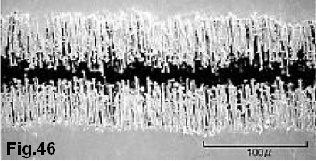 Maybe this is the technique used by Donald Smith to avoid the need for an earth connection. I have already mentioned about using negative energy to avoid the earth connection requirement in the Resonance Energy device but I can't guarantee that this is the method used by Donald Smith. Any questions, or suggestions are welcome via my e-mail: hopehope3012 (at) gmail (dot) com Part 2 This is an update for the above document with some corrections and a lot of new information, after publishing my pdf many people found it very difficult to understand, the concept depends on using the rotating electric component generated from the varied magnetic field to create a kind of excess energy present as a static electric field, instead of using normal wire it’s vital to use conducting foils to benefit from this excess of energy.  The extended Tesla bi-filar coil can be understood from another point of view which can explain a very interesting remark made by Don Smith, but before that, let’s start with Professor Konstantin Meyl when he explains Tesla wireless energy transfer using a model of a closed resonating L/C.  Prof. Konstantin Meyl described wireless energy transfer and at the same time the presence of overunity at the receiver, Fig 48 shows a kind of resonating transformer with excitation coil and a resonance L/C circuit on the secondary side, the circuit above can be modified as follows :  The separation of the resonant circuit takes place in the capacitor plate initially because it’s an open device, after that the secondary can be divided into two identical parts the same happens to the excitation coil:  The final situation is the famous Tesla wireless energy transfer device which composed of a transmitter and a receiver as shown in Fig.50. The interesting phenomena present in the reception side where overunity can be measured and seeing, the received voltage is much higher a published result by Prof. Konstantin Meyl is the input is 0.5 milliwatt and the output is 6 milliwatts The following photo show the used experimental kit:  On the right, is the transmitter and on the left, the receiver. Some very interesting values of the electric and magnetic fields have been measured as follows  The following photo shows the Tesla Monofilar flat spiral coil used:  Fig.52 is from Tesla’s patent 787,412 entitled ART OF TRANSMITTING ELECTRICAL ENERGY THROUGH THE NATURAL MEDIUM. Tesla was interested in using stationary waves for special purposes including wireless power transmission. Mutual induction is a weak point, so he decided to use a spiral form of the secondary coil C, this allow his stationary wave oscillator to work as expected. The mutual inductance is neglected in Tesla system but compensated for using a kind of capacitive coupling, something similar in Meyl device shown in Fig.53 where you can see the primary coil nearly surrounding the secondary many-turn coil, this is to cause as much capacitance as possible between the primary and secondary windings. If that is the case then why did Prof. Meyl see the maximum magnetic field but zero electric field in this area? The answer is the exchange of power when we have a resonance cause for this to happen, in the center of the secondary coil the winding gets smaller and smaller which allows a higher concentration of voltage, as you see there is an inverse relationship between magnetism and electricity in the scalar wave environment, Prof. Meyl explain this as a 90-degree phase shift between the electric field pointer and the magnetic field pointer, the overunity effect in the receiver can be also understood regarding this inverse relationship because the scalar electric field in the receiver is converted to a scalar magnetic field in the secondary few-turn coil, the conversion process in this case can convert voltage to electric current, beyond Ohm’s Law, overunity can be seen since the used current is very low (the used power was half of one milliwatt). The loss is very small, this explains why overunity is small when using higher power in that system. In my opinion, the reason is the increased electric current which cause more loss for example if you send 10 watts you receive only 11watts! In my opinion, both magnetism and electricity have to be taken into consideration in any such open system, the problem in the Meyl experimental kit is that you have to break the resonating LC circuit to achieve this, Prof. Meyl explains Tesla wireless energy transfer but not the overunity effect involved, if the capacitor is still present in the conducting two spheres the inductance is destroyed - see Fig.54  If the electric field lines are present, because we already have two spheres, the magnetic field lines are absent because the coil is divided as shown in Fig.49 to Fig.54. A divided coil isn’t similar to a single coil since there’s no shared magnetic field. According to Tesla there are two shapes which are suitable for radiant energy: the sphere shape or a cylinder. The wireless energy system can be divided into transmitter and receiver as follows:  The combination of Tesla Monofilar flat spiral coil with a sphere will give an extended Tesla Monofilar coil:  The transmitter in Tesla wireless energy transfer can be made as a single Extended Tesla Monofilar coil (“ETM”). The same can happen to the receiver. The idea in Fig.55 is understood now but we still have another problem and that is how to combine the two ETMs to make a single device? As explained before, we need to keep the coil unbroken, when combining the two ETM the coil has to be kept intact at the same time we could place the two ETMs so as to form a kind of capacitive coupling, the capacitive interaction here is strong because we have a wide area covered – see Fig.57  When combining two ETMs we have an Extended Tesla Bi-filar Coil (“ETBC”), in the first ETM we move from D to B and go to the second ETM starting fat point A and finishing at point C. In part 1 of this document I suggested using a spark gap between points A and B, but that kills the correct geometry because the coil is partitioned, all the experiments I did with some friends show there’s no useful power when putting a spark gap between A and B, so the correct configuration is the following:  When moving from point D to point B, the device forms a transmitter but from point A to point C the device forms a receiver. This looks like having a Tesla wireless energy transfer system acting in a single device, upon oscillation we shall have an excess of power in the receiver side, this explains the increased oscillations captured when using this corrected model:  Instead of using one capacitor to excite the ETBC it’s important to use two of them, with this each side is excited in the same manner which allow a better energy balance. Don Smith presented the following device as over unity example! one transmitter and three receivers:  Each receiver gives the same amount of power sent by the emitter, it's possible to replicate the power according the receiver we have, in this case we have three receivers, 3 times more power than the input, in the case of ETBC each side DB or AC can be either a transmitter or a receiver so the amount of gained power is proportional to the working frequency, it’s clear the ETBC is superior compared the example given by Don Smith but as we see the idea remain the same (hint)… The concept energy balance need a little explanation because it’s related to the special capacitor that exist inside the ETBC:  Because the ETBC form another resonating L/C circuit where everything situated in the same device, I could say that there’s a symmetry between magnetism and electricity in it, I think we need to dig deeper to approach the concept of electron spin given by Don Smith. If we divide a magnet into small parts, each part will form another magnet, if we continue with it we find that an iron atom acts as small magnet:  If we replace a magnet with a coil and we the repeat the subdivision, then we find that an electron acts as a small magnet, the magnetic field in a straight wire forms a circle around it, this suggests that the electrons do spin to make a closed magnetic field as shown in Fig.63.  In a solenoid coil the electrons spin in the same direction along the coil. In Fig.63 you see that the coil is divided into two identical parts where the electrons take the same direction of rotation and so the magnetic field flows along the coil. The mistake in part 1 of this document was talking about an electric current that doesn’t exist! The reason is the absence of a closed loop to introduce an electric current, in this case the electron spin takes the lead. To explain this, let’s take another look at the scope graph in Fig.59:  The marked area shows an absence of voltage. In that experiment, no ferromagnetic material was used, only aluminum foil, the voltage is zero so it’s expected for the ETBC to stop the oscillation but the device acts once again! This means that there’s an accumulation of magnetic flux inside the ETBC, in other words it’s a magnetic field without an electric component, the magnetic field in this case is present as electrons spin potential which gives a better picture of the presence of the Bloch wall area in the ETBC. This device looks like a dynamic permanent magnet, this explains the statement given by Don Smith about the similarity of his device with an ordinary permanent magnet power generator. Now it’s absolutely clear the ETBC needs a kind of energy balance to oscillate correctly. As explained in Fig.59, two capacitors are needed to arrange a kind of spin balance inside it, I said the ETBC forms a special capacitor coil but this is not exactly true! In reality, there’s no coil nor a capacitor! Both the coil and the capacitor need an electric current but the ETBC needs an energy balanced electron that can be supplied only if the same amount of positive charges meets the same amount of negative charge. Ming Cao, a developer in mainland China, comments on the designs of Don Smith, and Tariel Kapanadze. He says: None of these things originate from me, they come from Tesla and God.
I get all these by low voltage from a signal generator, as I haven't finished building a high voltage device yet, although I'm already working on it. But I think it's safe for me to believe that these results are solid and good enough to share. Here is a image from Tesla's patent 593,138 Electrical Transformer.  We can see it's exactly the same as Nick Giannopoulos' setup, except that Tesla is using a generator in this diagram, I believe for simplicity. As long as the generator is generating the exact frequency of current, it will work fine. The secondary at the energising side is a quarter-wave coil, and at the pick-up side is another quarter-wave coil. The highest voltage is at the far end of these two secondary coils and their connecting wire, and zero voltage is at the very outside turn of each of the coils. Now if we change the spiral form coil to helical, it becomes Nick's set-up. And let's take this further, we can shorten the connecting wire until the two solenoid secondary coils actually become one big coil, then, when combined it is a half-wave coil, and the highest voltage is at the middle point of it. Now it becomes Don Smith’s and Tariel Kapanadze’s device, like this: 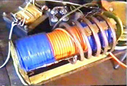 Because the energy is also coming back from the energising side, Kapanadze adds another pick-up coil right underneath the primary energising coil. This arrangement, I think, is very hard to replicate, because it is so very hard to tune, for several reasons:
Don Smith did indeed say something useful. He said that we can make the secondary coil a fixed size, and then slide the primary coil inside it. Well based on experimental results, this sliding process is altering the actual effective length of the secondary coil. In general, we should assess coil size by counting the turns from the turn right underneath the primary energising coil, to the turn right underneath the pick-up coil, this section is the actual secondary, and this section should be a half-wave resonate coil, the rest of the coil just sits there doing nothing. But it's not that simple, the terminals of the secondary coil should connect to the earth or to a large sphere, or a typical Tesla Coil secondary with the same quarter-wave resonant frequency. Otherwise the signal will bounce backwards and forwards in the coil producing a mess, or generating an arc, and this is bad for performance, and this is why a solid ground connection is desirable. And this is the true meaning when Don says "slide the primary coil to do the fine tuning". So, returning to the Kapanadze device, the energising coil covers a large area of the secondary coil, making the effective length of the secondary coil very much shorter, again, boosting the working frequency of the device even higher. For such a device, it is impossible to tune it without a 20Mhz signal generator, an oscilloscope and complete understanding of how a longitudinal wave behaves. For a start, I don't even know where to connect the oscilloscope probe or which terminal should connect to the ground, I'm so lucky to be able to watch Eric Dollard's old video, and I recommend everybody to watch that video, watch it over and over again, also many other educational videos from Eric. A lot of fundamental stuff about how a longitudinal wave behaves are explained there, it's like a treasure map covered in dust in a quiet corner of an open library. Ming’s video demonstrates what he is saying here. For the video he uses an input coil, a monitoring coil and a secondary coil, each end of which is earthed using separate earth connections:  Ming also remarks: For the set-up in the video, the secondary coil is wound using 1mm diameter enamelled copper wire, 365 turns around a 160mm diameter PVC pipe. The total coil length is 39.5cm. The total wire length of the secondary is approximately 182m. The white material is several layers of insulating glue to prevent arcing between adjacent turns when working with high voltage. The primary coil and the pick-up coil are wound with audio cable which is more than 4 square millimetres in cross section. The primary coil has 2 strands, 2 turns. The pick-up coil has 4 strands and only one turn. I use this thick wire, because I am going to use these coils for my high voltage project. For a low voltage experiment like shown in the video, it would be quite adequate to use ordinary copper wire of 1 square millimetre cross section (swg 18 or AWG 17). If the secondary wire length is reduced, then the resonant frequency will be higher, but the principle is the same. If only low voltage is going to be used - perhaps just to study the nature of longitudinal waves, then the secondary coil can be made using very thin wire of 0.3 to 0.4mm diameter (swg 30 to swg 27) enamelled copper wire, this will cost much less. I made my coils with thick wire because I intend to continue using high voltages. It's been a long time, but I've got some more understanding about harnessing radiant energy. I have made two additional videos: video 1 and video 2 In these two videos, I explain the method of converting Tesla's ‘cold’ electricity to normal ‘hot’ electricity by storing it in a capacitor. I strongly believe that, the method shown in the second video is exactly what Don is doing with his famous device, which has no pick-up coil, just a two-part secondary. In the first video, I replace the pick-up coil with an uncoated sheet of copper, to show people that, this is not a transformer, and so, is not based on electromagnetic induction. The pick-up coil is fundamentally, a piece of metal which can be electrified by a longitudinal wave. I can remove the diode and the capacitor, and just let the copper sheet discharge to ground through a spark gap and two ordinary 200-watt incandescent light bulbs connected in series, the light bulbs are pretty bright although not fully lit, but pretty bright in spite of this being a non-resonant situation. They look like this: 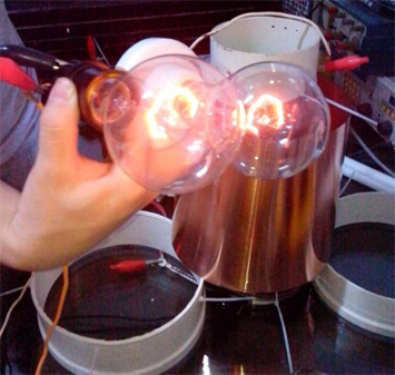 The copper sheet is electrified, and it’s charge is flowing to ground, and it is this very process which forms the current. So if we consider it as a transformer, and consider the pick-up coil as a inductor, and add a load to this "inductor" to form a closed loop, then we are going in the wrong direction. Then I re-read about Nick Giannopoulos' device, and I noticed that he said that the light coming from his bulb is blue and white. Following his circuit diagram, I believe that it is like this:  I get this kind of light when I attach the light bulb directly to the sheet copper without an earth connection or any other additional wire. Here at this stage, we have no ‘hot’ electricity. The blue-white light is caused by the high voltage of the metal, to which the bulb is attached. The high voltage is not caused by induction, it is purely static charge on the metal surface, caused by longitudinal wave electrification. If we use Tesla's specially made bulbs as shown in his lectures, we have his single-wire lighting system, and we will have a very bright light suitable for general-purpose lighting instead of this kind of blue-white light. Generally speaking, my bare copper sheet is the equivalent of Nick's pick-up coil plus his step-down transformer, which, of course, is not a transformer at all. Note: As will be seen in the videos, Ming uses two separate earth connections. One is the earthing wire of his mains electricity and the other is a connection to his cold water pipes. A Russian developer has lit a large light bulb with a self-powered Kapandze-style circuit:       Video here shows self-powered bulb (needs an earth connection): 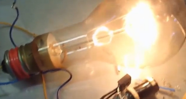 A Chinese developer has replicated Don Smith’s main device very successfully. Using an input of 12V at 1A to 2A (24 watts) he is lighting ten 100-watt light bulbs to a high level of brightness. The Chinese language video relating to this can be seen here. Here are some of the frames from that video: 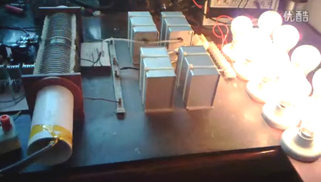 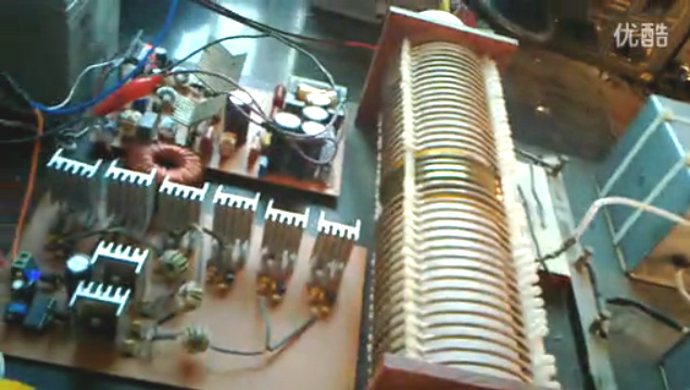 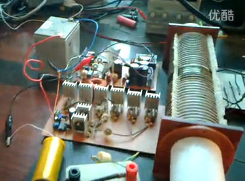 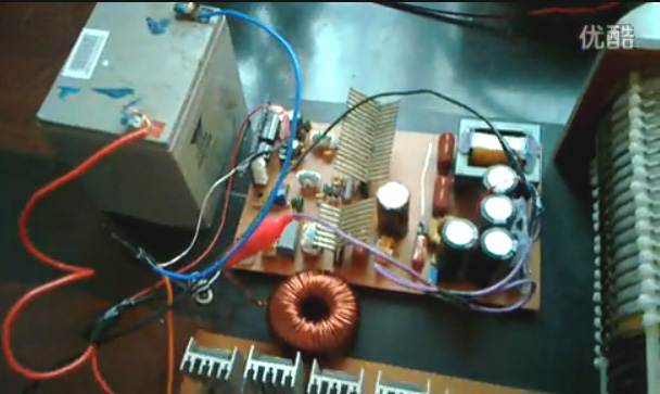 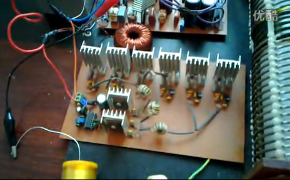 The circuitry used is shown here:   Subsequently, a forum post by a Mexican man says: Hello ‘Salty Citrus’, I love your video!!!! I can really appreciate the amount of work you and your group have spent to develop and perfect the Don Smith / Tesla free-energy device. Thank you for pursuing such a noble cause. I am intrigued by your switching network using the CREE CMF20120. How did you wire the MOSFET's? You used a UCC3825A Pulse-Width Modulator to clock the signal --> MOSFETS --> Gate Drive Transformers (x3) --> push-pull transistors --> CMF20120? Did you run the CMF20120 in series? Sorry about so many questions, but I am totally impressed by your ingenuity, and completely agree that your solid-state solution has undoubted benefits over Tesla's conventional spark gap. I would be honoured if you could take the time to answer my questions. I would love to replicate your circuits. I wish you the best of luck with your endeavours. Sincerely, ‘Lost_bro’ (half a world away) Re: ‘Lost_bro’ Thanks for the compliment. The success does credit to my team. Thanks to my team. Yes, the CMF20120 run in series in this solution. The voltage balancing between each MOSFET is critical as is the balancing between RC and DC voltage created by R. Welcome to our forum for the exchange of information. China is an hospitable country. If you have any information or ideas, please don’t hesitate to share them with us. ‘Half a world away’ is not a great distance. All the best, Sincerely ‘Salty Citrus’ An earlier entry on the Chinese forum translates as: Here is an earlier build. It is simple and has no step-down section and so cannot be self-powered: 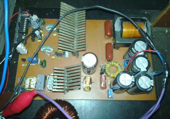 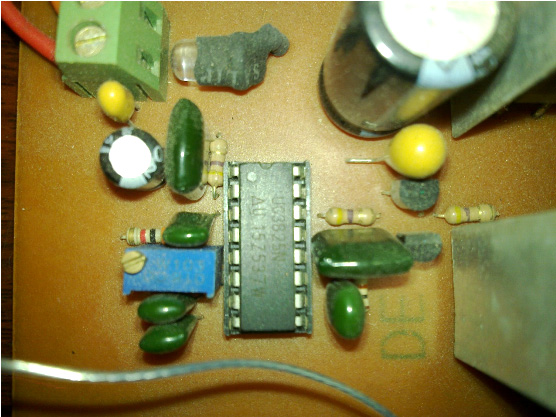 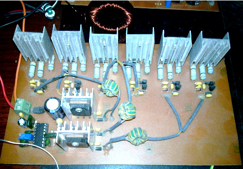 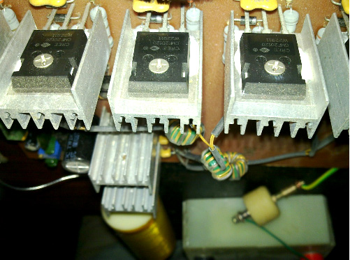 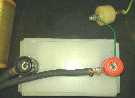 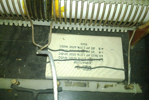 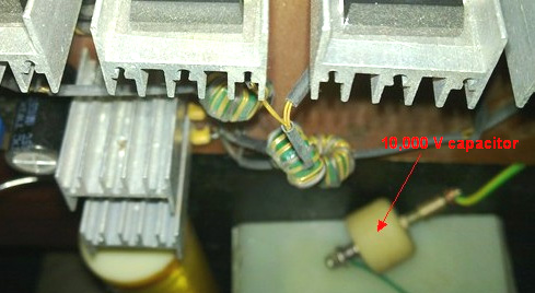 Each bulb is 100 watts. The first board has a 12-volt input and an adjustable output which can be varied from 500V to 1600V (any higher voltage would damage the four 450V 20 microfarad capacitors). In the video, the variable resistor is used to set the voltage level of the FBT after boost as the voltage step-up circuit can go up as high as 3,000 volts. The L2 coil is wound in a single direction and has just one tap at the centre. The idea is from Tesla’s Colorado Springs Notes, in which Tesla disclosed the best method for a resonant driver. The frequency used in this circuit is about 230 kHz. Question: There is nothing to do with quarter-wavelength, but is there anything with the length of the L1 and L2 coils on quarter-wavelength? Answer: I think that the phase is more important. Question: Do you need a Phase-Locked Loop circuit with a certain phase difference? Answer: Basically, I use a fixed frequency, I have tried a Phase-Locked Loop and the effect is the same. Question: Do you use direct drive with the spark gap only being used to limit voltage? Answer: You can use a vacuum tube to drive it. Question: If you drive it directly, then the loading will be very big and the current will increase, whereas if you use a spark gap, then the spark will become smaller and the current will be steady. Answer: If the load affects the input, then you cannot drive it even with a spark gap. If you trigger with a spark gap, then the load will not increase the input. The spark gap is just a switch. Question: Is there any direct Lenz relationship between the load and the primary? Answer: Once the phase has been adjusted, the primary has no adverse effect on the secondary. Commenting on his circuitry, ‘Salty Citrus’ states: The diode symbols with a tick indicate a Zener diode (or bidirectional TVS-Transient Voltage Suppressor or “varistor”). For example, in this circuit, they are used to suppress the Grid voltage of the MOSFET, to maintain the gate voltage within the range of +20V to -20V. The above circuit is just a description of the structure of the MOS series method. Specific components will be needed for your own requirements considering the MOSFETs being used in your construction. The voltage E0 can be adjusted. The source can be made using a TL494 IC operating at 12V, or alternatively, an adjustable, voltage-stabilised inverter can be used. The voltage setting depends on the numbers of MOSFETs which are being used in series and the parameters of Grid voltage and the turns ratio of the isolation transformer. The circuit is arranged so that each MOSFET has its own separate isolation transformer, and all of the primary windings of those transformers are connected in series to form a single current path. The number of turns in the primary of each isolation transformer is exactly the same. To drive an IGBT(or MOSFET), VT6 provides a high-frequency pulse current to drive the Gates of the MOSFETs, so as to achieve consistent switching. In my circuit, the frequency used is 220 kHz, for this frequency, I use six MOSFETs type CMF2012 (1200V, 37A, Resistance Drain-to-Source of just 80 milliohms). This MOSFET from CREE has excellent performance, but you have to design the drive circuit carefully, 2V to 22V for the Gate voltage will be best. I particularly stress that it is very important that MOSFETs operated in series, require voltage balancing and an accurate drive. Especially important is having synchronized drive signals and the rise and fall time of the drive signal should be as short as possible, so that the switching time difference between the MOSFETs will be short, and that improves the high frequency operation. Another Russian Development At www.youtube.com there is a video which shows a self-powered motionless generator with an output of 105 watts: 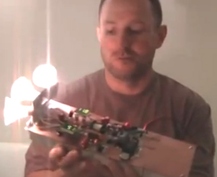 Thanks are due to Wesley for his translation of the Russian soundtrack. No circuit details are available that this time, but the video has “Part 1” in the title and so further details may be provided at a later time. Tesla Coils Back-to-Back I have been told of one man who used his common sense and produced an impressive result. He used a Tesla Coil as the driving force, and then used a second Tesla Coil back-to-back with the first one, to step the high voltage back down again. Doing that, he was able to light a series of powerful light bulbs from the “L1” output coils. He also confirmed that doubling the voltage, quadrupled the power output, verifying what Don said. He also found that adding additional coils with bulbs to the output Tesla Coil, did not increase the input power at all, did not cause any of the existing light bulbs to shine any less brightly, and yet lit the additional bulbs. That would appear to be confirmation of Don’s statement that any number of magnetic copies of the original oscillating magnetic field of the first Tesla Coil, can provide a full-power electrical output without requiring any additional input power. I’m no expert, but my understanding of the arrangement is:  As the large diameter coil is exactly one quarter the length of the smaller diameter coil, there is an automatic resonance of both when the applied frequency is just right. As the first narrow coil is identical to the second narrow coil, they are also automatically resonant together. Again, as the large coils which feed the loads are exactly one quarter the wire length of the narrow coils, they also resonate at the common frequency and at that frequency, the input power is at its minimum while the output power is at its maximum. The spike at the top of each of the narrow coils is connected with a wire to channel the generated power from the first Tesla Coil to the second one. This arrangement may seem too simple to be effective, but with Tesla technology “too simple” just does not apply. This can be seen clearly from the work of Nikanor “Nick” Giannopoulos. Before he ever learned anything about electronics, Nick read and understood Nikola Tesla’s “Colorado Spring Notes” (pdf 60Mb) and this helped with his present level of understanding. Interestingly, and perhaps not surprisingly, Nick had difficulty with conventional electronics after becoming familiar with Tesla’s technology. Nick used a square wave signal generator adjustable from 50 kHz downwards and with a fully adjustable Mark/Space ratio. This was used to drive an oil-filled car ignition coil, which, as he points out is not a Tesla Coil in spite of the frequently held view that it is. Ignition coils only operate at low frequency due to the limitations of their core material. However, John Stone points out that certain coil designs, such as those for the Fiat ‘Punto’ car, are built in such a way that replacing the core with ferrite should be possible, and that would allow high frequency operation. Anyway, Nick uses a standard car ignition coil at lower frequency and uses it to feed a spark gap like this which is constructed from two chipboard screws: 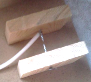 His circuit is:  Nick has had very impressive results from his circuit, although it is still very much a work in progress with more development and testing still to be done. The 24 watt input of 12V at 2A is producing two very brightly lit 220V light bulbs. This does not tell us very much about the actual output power as bulbs are notorious for lighting brightly at low power levels, especially if the frequency is high. But, a very important point is the quality of the light which is an unusual, blue-white colour, quite unlike the colour produced when connected to the 220V mains supply. This is generally a sign of the power being ‘cold’ electricity. While he has not yet had the opportunity to test it, Nick believes that the circuit as it stands now is quite capable of powering much higher loads, and considering the colour of the light, I would be inclined to agree with him, although anything like that has to be tested and proven before any solid conclusions can be drawn from what is already known about the performance. The circuit performance is much improved if two separate physical earth ground connections are made. 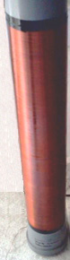  Please don’t fall into the trap of thinking that because the sparks are occurring at less than 5 kHz, that the Tesla coils also operate at that frequency. If you strike a bell which vibrates at 400 Hz, does that mean that you have to hit it 400 times every second in order to hear it? Actually, no, you don’t, and the same thing applies here where the resonant frequency of the Tesla coils is approximately 650 kHz. The primaries are wound on 100 mm diameter PVC pipe sections and 19 turns of 1.02 mm diameter enamelled copper wire is used for them (19 swg or #18 AWG). The secondary coils are wound on 70 mm diameter PVC pipe using 0.41 mm diameter enamelled copper wire (27 swg or #26 AWG) with a total length of four time the primary winding wire length. As you will see later on in this chapter, resonance in a coil involves a standing wave inside the wire. That standing wave is created by the signal bouncing off the end of the wire and being reflected back. At frequencies other than the resonant frequency, this results in a constantly changing set of many different waves travelling in both directions and at different intensities (what could reasonably be described as a total mess). When the resonant frequency is fed to the coil, then all of that mess disappears and just one waveform remains, and at any point along the wire, that waveform appears to be stationary although, of course, it is not actually stationary, just the effect of the peaks always occurring at exactly the same spot and the troughs occurring at exactly the same spot, making successive waves look exactly the same as the previous one. This feature has one very practical aspect, namely that if you run the same wire away from the coil turns to connect to whatever the next circuit component happens to be, then the wave inside the wire will not bounce back at the end of the coil turns but will continue on to the end of the wire before bouncing back. So, the connecting wire length has to be included when reckoning the wire length in the turns of the coil. On the other hand, if the wire in the coil turns is terminated at the ends of the coil and wire of a very different diameter is used for connecting to the next component in the circuit, then the signal inside the wire will bounce back from the sudden change in wire diameter and so the connecting wire length will not be part of the wire length in the turns of the coil. This is an important feature if you are aiming for an exact 4:1 wire length ratio (and 4:1 wire weight) between the Tesla Coil windings in order to impose an automatic resonance between the two windings. It should be noted that PVC (especially non-white PVC) has a very restrictive effect on high frequency coils. At low frequencies, PVC is ok, but it drags down the coil performance as the frequency rises, lowering the “Q” (for “Quality”) factor of the coil. Using acrylic instead of PVC overcomes this. Alternatively, coating the PVC with a high-voltage insulating material such as shellac or one of the proprietary coating agents, will improve matters considerably. The ideal, of course, is to have no former at all and have the coil standing unaided because of it’s own strength. The method of making that style of coils shown later on in this chapter. The Screened Transformer of Joseph Boyd. It is not at all clear if the Boyd power system should be located here or in chapter 7 which deals with aerials. Joseph talks about the way that radio circuits operate and why only very limited power appears to be the limit of radio receivers. He explains a method of extracting serious levels of power from a transmitting coil and a receiving coil, but the higher power levels require an input oscillator, and so, while an aerial and earth can be used for lower power levels, input power is needed for optimum performance. Here is part of Joseph’s patent application: ELECTROMAGNETIC ELECTRIC GENERATOR Abstract: An electrical generator that uses a high frequency oscillator in a tuned circuit, set to resonate with the transmitter coil of a full-length high frequency transformer unit, to generate electromagnetic energy, to transform this energy to electrical energy and to collect this energy. 1. Field of the Invention The present invention is an electrical generator that uses a high frequency oscillator in a tuned circuit, set to resonate with the transmitter coil of a full-length high frequency transformer unit, to generate electromagnetic energy, to transform this energy to electrical energy and to collect this energy. 2. Description of the Related Art If an oscillator circuit is properly connected to a tuned antenna so that it resonates, a current will flow between the aerial and the ground, and this produces the high frequency electromagnetic air waves and ground waves of our radios and other electronic equipment. An oscillator of the same type used in electromagnetic wave transmission equipment is used to generate the electromagnetic energy used in this patent. These electromagnetic transmitters are well developed and are used world wide, and broadcast at frequencies that extend from the longest radio waves to the very short ones. Certain radios send their signals great distances, some even travelling around the world. Although these high frequency electromagnetic energy waves are all around us, this energy has long been considered impossible to collect on a large scale due to the induction characteristics of the electromagnetic wave as it passes a metallic object. As the wave goes by a wire tuned to resonate at the frequency of the wave, it induces an electrical charge in the wire, but to use this charge, we need another wire to close the circuit and let the charge flow. If we use another wire alongside the first wire and connected to it, the wave induces a charge in it exactly like in the first wire and no current will circulate in the two wires. This problem of collecting the energy of the wave was solved by the invention of the half-length electromagnetic transformer, but the half-length electromagnetic transformer applies only to the means of collecting the atmospheric energy. The invention of the full-length electromagnetic transformer of this invention, however, allows us to combine the generation of the electromagnetic wave and the electrical converter into one compact unit. BRIEF SUMMARY OF THE INVENTION Basically, this unit uses an oscillating electric current to generate an electromagnetic wave, which releases a much greater electric current, and the total electrical energy derived in this manner, is over and above the amount of energy needed to operate the equipment. It has long been assumed that the only energy involved in high frequency electromagnetic transmission is that supplied by the operator to drive his equipment. The actual energy of the electromagnetic wave is often over a hundred times greater than this since the amount of electromagnetic energy in the earth is practically unlimited, there appears to be no limit to the size of the electromagnetic generators, or to the size of the power plants based on this energy source. This energy is available, world wide, free for the taking. This energy is related to the light waves and is probably a variation of the light waves, however, the radio type waves are longer than light waves and are vibrating at a lower frequency. Light waves are a source of high energy just for the taking, also. Anything that is brought up to a high heat, will give off light energy. A very small wire in a light bulb, when brought to a high heat will release a light ray of such power that it will go all the way to the moon. This is natural energy, produced by the speed of the earth through space. Using the math of Dynetics, the speed of the earth necessary to give any pound of earth the atomic energy of one pound of uranium, came out exactly the same as the speed of light (186,300 miles per second). The fact that the math came out exactly at this speed leaves little doubt that the speed of the earth through space is the speed of light, and that every pound of material on earth has the energy of one pound of uranium, due to this speed. The electromagnetic energy in the low frequency range differs from other types of energy, in many ways, but of interest to us is that it is propagated by electrical currents, travels through the air like the light waves, and is detected and may be collected, when it induces an electric charge in a wire. This is an ideal source of energy. The generators may be hand-held or large enough to replace the biggest power plants. They may be used to drive motor cycles, sleds, autos, trucks, trains, ships and planes. The fact that the output is in the form of electrical energy is, in itself, a great benefit, but the fact that the generating equipment is light and compact is a real plus for all types of mobile equipment. It is possible that this invention will supply all of the electrical energy needed in the homes making the distribution lines unnecessary, and if used to drive automobiles, our dependence on oil will be a thing of the past. This invention makes possible an abundance of energy, available to mankind any where in the world. Even the poorest nations will have an abundance of energy. The oscillating equipment that generates the electromagnetic wave used in this invention includes an oscillator, of some type driving a tuned transmitter coil that resonates with a tuned collector coil in a full-length electromagnetic transformer. The induced current is collected in the collector coil and may be rectified and stored in a battery or used to do work. The oscillator circuit is an ordinary oscillator circuit, driven by a tube, crystal or even an electoral arc, and the tuning means and rectification set-up are standard. The basic element that is novel to this invention is the full-length electromagnetic transformer unit that is made up of two or more metallic pipe like sheaths side by side. The sheaths are not connected together, electrically. Two or more coils are wound in the sheaths. The transmitter coil uses an insulated wire, which is threaded up through one sheath, and down through another sheath a number of times forming a long flat continuous circuit of wire inside of the pipe like sheaths. And then the collector coil is threaded up through the sheaths, and wound the same way. The two coils may have a different number of turns. The coils are tuned to resonate at the oscillator frequency and an electromagnetic wave is generated in the transmission coil. The wave induces a charge in that part of the collector coil that is in the same sheath, and next to it, and if the wave is moving up in the sheath, the charges of all of the collector wires in that sheath are moving up, and if the wave is moving down, the charges of all of the collector wires are moving down. But the transmitter wave in one sheath does not induce a current in the wires of another sheath, nor does it induce a current in a wire outside of that sheath. This allows a current induced in one sheath to freely circulate in the other sheaths or on an outside wire. When the transmitter coil is brought up to resonance and broadcasts its electromagnetic wave inside of the sheaths, it benefits us in two ways. It keeps the wave inside of the sheaths and prevents it from spreading far and wide, and it concentrates the wave on that part of the collector coil in the same sheath. Since each of the collector wires are of the same length, say ½ wave length of the electromagnetic wave, and since they are parallel and side by side, a resonant electromagnetic wave induces equal charges in all of the collector wires within the sheath. These induced currents are exactly in phase and are connected in series, so that the voltages add up to an amount proportional to the number of turns. More than two sheaths may be used with the coils wound inside, or the ff11 length-transformer may be combined with the half-length transformer where the winding is part inside the sheath and part outside of the sheaths. The oscillator may be replaced by an aerial in cases where low power is needed. The inductance coil may be left entirely outside of the transformer, and the coupling made to the transmission coil by magnetic induction. These and other objects, features and advantages of the present invention will become more apparent upon reading the following specification in conjunction with the accompanying drawing figure. BRIEF DESCRIPTION OF THE FIGURES  Fig.1 is a view of an electromagnetic wave, due to resonance, passing two side by side wires tuned to the same frequency. The wave generates equal alternating charges in each wire, and no current flows when the wires are connected.         DETAILED DESCRIPTION OF THE PREFERRED EMBODIMENTS When a circuit is made to resonate at some frequency, it generates an electromagnetic wave. These waves move at the speed of light and travel great distances, and this makes possible our radios, televisions and cell phones. These waves, in passing a wire suspended in the air, set up alternating charges in the wire, varying at the frequency of the wave. If we put an inductance, that is tuned to the frequency of the wave, between the wire and the ground the circuit will resonate and charges will flow back and forth on the wire. This allows us to pick out the wave we are interested in, amplify it and read its message. We have long known that the voltage of the wave we choose to receive is greatly amplified when we make our circuit resonate at that wave's frequency, but we have been unable to accumulate this additional energy from the wave because we are limited to what energy we can pick up by the equipment that we use. Fig.1 shows why this is so. The passing electromagnetic wave 6 generates an alternating electric charge in the wire 10, tuned to the wave frequency to close the circuit so that the induced charge can circulate, we have added a second wire 11, but if we connect the ends of the wires together, the electromagnetic wave 6 induces a charge in the second wire exactly like the one in the first wire, and no current will flow. Any effort to circulate the charge induced in wire 10 is blocked by an equal opposing charge in 11. In Fig.2 we have replaced the wire 11 with a metallic, pipe like sheath 13 having an insulated wire 14 inside when an electromagnetic wave 7 passes, the wave is stopped at the sheath 14 and does not induce any charges in the inner wire 14. This allows the inside wire 14 to conduct the charge induced in the wire 12. In Fig 3 we see two sheaths 20 and 21, parallel and insulated from each other. Two separate coils 22 and 23 are wound inside the sheaths. The coil 22 is the transmitter coil and it is tuned to resonate at the frequency of the oscillator circuit 24, and this generates an electromagnetic wave that induces a current in the collector coil 23, which is adapted and used in the tuned collector circuit 25. Fig4 is a view of a full-length electromagnetic electric generator using two separate sheaths 30 and 31, where the electromagnetic wave is almost completely contained within the sheaths. The sheaths are parallel and insulated from each other by insulators 34 and 35. The transmitter coil 32 and the collector coil 33 are shown in the cut-away, and are wound completely inside the sheaths. Additional coils may be added as needed. The transmitter coil 32 is tuned to resonate at the frequency of the oscillator circuit, which connects in at 36. And this generates an electromagnetic wave that is contained within the sheaths and induces a current in the collector coil 33, which is tuned to resonate at the wave frequency and is coupled to the collector circuit at the terminal 37. The insulating separators 34 and 35 are necessary to prevent induced current from flowing in the sheaths 30 and 31. A number of sheaths may be combined, as is shown in Fig5. In this case four sheaths 40, 41, 42 and 43 are combined, so that the coils wound inside the sheaths are in series, and the sheaths are electrically separated by the insulators 44, 45, 46 and 47. The tuned circuit for the transmitter coil is hooked up at connectors 48, and the collector circuit connects to the collector coil at 49. A simple circuit for operating the full-length electromagnetic transformer is shown in Fig.6. The two sheaths 50 and 51 are shown with the transmitter coil 52 and collector coil 53. The transmitter coil is connected to the tuned circuit 55, which is driven by the oscillator 54. The oscillator 54 is tuned to oscillate at some frequency and the transformer circuit 55 and collector circuit 56 are tuned to resonate with it. At resonance the transmitter coil 52 emits an electromagnetic wave which induces a current in the collector coil 53. Shown here is a half-wave rectifier 57 and capacitor 58 connected to the load 59. The rectifier is necessary on each collector unit, because we can add the direct currents of the separate units, but the alternating currents of the units might be out of phase and without the rectifier they would cancel out. Fig.7 shows the transmitter coil connected between an aerial and the ground, where the aerial circuit and collector circuit are tuned to resonate at a desired frequency to greatly boost the sensitivity and to amplify the signal. This type application will work equally well with transmitters. Also, using the half-length transformer as an aerial and the full-length transformer as the radio frequency transformer works the same with both receivers and transmitters. The oscillator circuit can use a high frequency magnetic inductance and the full-length transformer unit to resonate with a half-length transformer which acts as an aerial. A unit such as this would greatly add to the power of a radar system. The full-length units, when combined with rectifiers, may be connected in series as in Fig.8, or in parallel as in Fig.9. While the invention has been disclosed in it’s preferred forms, it will be apparent to those skilled in the art that many modifications, additions, and deletions can be made therein without departing from the spirit and scope of the invention and its equivalents as set forth in the following claims. Claims: 1. An electric generator that uses an oscillating circuit to resonate with inductances enclosed in a full-length electromagnetic transformer unit, comprising: two or more parallel, metallic, pipe-like sheaths, insulated from each other; an electromagnetic transmitter coil, which is wound inside the sheaths, using an insulated wire, threaded up through the inside opening of one of the sheaths and down on the inside of a second sheath, one or more times, to form a continuous coil; a means of tuning the transmitter coil to the frequency of the oscillating circuit, so that the transmitter coil resonates and generates an electromagnetic wave that is contained within the sheaths; a collector coil composed of an insulated wire, threaded up through the inside opening of one of the sheaths and down on the inside of a second sheath, one or more times, to form a continuous coil, wherein the electromagnetic wave of the transmitter coil induces an electric charge in the collector coil; and a means of tuning the collector coil to resonate at the frequency of the oscillating circuit; so that the electromagnetic wave induces a current in the collector coil, and since the coil is contained within the sheaths, the current is free to flow, and the high frequency alternating current, so generated, can be used elsewhere in an electronic circuit, or altered and used as a power source. 2. The full-length electromagnetic transformer unit of claim 1, where the collected current is rectified, and the DC current is stored in capacitors and used to do work. 3. The full-length electromagnetic transformer unit of claim 1, where the transmitter coil acts as a tuned inductance, in a receiver, between the aerial and the ground, and a tuned collector coil resonates to increase the sensitivity and the amplitude of the signal. 4. The full-length electromagnetic transformer unit of claim 3, where the tuned transmitter coil resonates with an oscillator and an aerial to act as a transmitter for radios, televisions, cell phones, radars and computers. 5. The full-length electromagnetic transformer unit of claim 1, where the lengths of the sheaths are some multiple of the wave length of a particular electromagnetic frequency. 6. The full-length electromagnetic transformer unit of claim 5, where a number of the units are connected in parallel to increase the current. 7. The full-length electromagnetic transformer unit of claim 5, where a number of the units are connected in series to increase the voltage. 8. The full-length electromagnetic transformer unit of claim 5, where the parts are reduced to a size small enough to fit in, and supply power to, a cell phone, a lap-top computer, or other electrical appliance. 9. The full-length electromagnetic transformer unit of claim 1 further comprising three or more, metallic, parallel, side by side, pipe like sheaths, where the sheaths are not electrically connected, and have two or more coils wound inside the sheaths. Up to the present time (June 2013), I have not heard of anyone attempting to replicate the design shown in this patent, and so it is just being put forward here in case somebody wants to try it. It appears to be a clever technique. The power gain is maximised by tuning the transmitting and receiving coils to the frequency of the oscillator, although in practice, it is highly likely that the oscillator frequency would be adjusted to the transmitter coil as it is so easy to adjust the frequency of an oscillator. Boyd does not go into great detail about attaining resonance, and that is generally a major difficulty in any design which does not have automatic tuning. It needs to be borne in mind that the length of wire in each coil (and possibly its weight) is a key factor. Boyd talks about the coils possibly having the same number of turns, and that is fine provided that the coils are identical in size, that is, having the same shape when viewed from the top and the same depth of turns when viewed from the side, and exactly the same number of turns with each coil having exactly the same wire length. Resonance in a length of wire, whether it is laid out straight or wound into a coil, tends to confuse many people. Richard Quick’s very clear explanation of resonance in any length of wire, in his US patent 7,973,296 of 5th July 2011 is very helpful. He says: “Quarter-Wave” Resonance; Standing Electromagnetic Waves” One of the two main types is electrical resonance is referred to here as quarter-wave resonance. This type of resonance depends almost entirely on the length of a wire element For reasons described below, if a segment or length of wire is one quarter as long as the “voltage waves” which are travelling through the wire, then a set of “reflected” waves will be added to the emitted waves, in a synchronised alignment which creates stronger “superimposed waves”. Accordingly, an understanding of the “quarter-wave” phenomenon will help a reader understand how a straightforward and easily-controlled factor (i.e., the length of a wire ribbon which will be used to form a spiral coil) can help create a “quarter-wave” resonant response, which will create the types of electromagnetic pulses and fields referred to as “standing waves”. The speed at which a voltage impulse is transmitted through a metal wire is extremely fast. It is essentially the same as the speed of light, which travels 300 million meters (186,000 miles) in a single second (that distance would circle the earth more than 7 times). If wavelength (in meters) is multiplied by frequency (cycles per second), the result will be the speed of light, 300 million meters/second. Therefore, the wavelength of an “alternating current” (AC) voltage, at some particular frequency, will be the speed of light, divided by which frequency. Therefore, using simple division, if an alternating voltage operates at a frequency of 1 megahertz (MHz), which is a million cycles per second, then the “wavelength” at that frequency will be 300 meters. If the frequency halves become 500 kilohertz, the wavelength becomes twice as long (600 meters); and, if the frequency were to increase to 2 megahertz, the wavelength drops to 150 meters. It should be noted which the term “cycles” is what scientists call “a dimensionless unit”, which drops out and becomes silent when other physical terms are multiplied or divided. At AC frequencies of 10 kilohertz or greater, the common references to “alternating current” (AC) voltage begin using a different term, which is “radio-frequency” (RF) voltage. Accordingly, RF voltage is a form (or subset) of AC voltage, which operates at frequencies higher than 10 kilohertz. RF power generators are readily available, and are sold by numerous companies which can be easily located by an Internet search, using the term “RF power generator”. For example, Hotek Technologies Inc. (hotektech.com) sells two RF power generators, called the AG 1024 and AG 1012 models, which can provide output power at frequencies ranging from 20 kHz to 1 MHz; the 1012 model has a power output of 1000 watts, while the 1024 model has a power output of 2000 watts. The output frequency of any such RF power supply can be adjusted and “tuned” across the entire range of operating frequencies, merely by turning knobs or manipulating other controls in a power supply of this type. In a wire having a fixed and unchanging length, the easiest way to create a “standing wave” is to adjust the RF frequency emitted by a power supply with an adjustable frequency, until the “tuned” frequency creates a wavelength which is 4 times as long as the wire. This principle is well-known to physicists, and it is commonly referred to as “quarter-wave” behaviour, since the length of the wire segment must be one quarter as long as the wavelength. Since it is important to this invention, the principles behind it are illustrated in a series of drawings provided in Fig.1 to Fig.4, all of which are well-known prior art.  Fig.1A indicates an idealized wavelength of an alternating voltage, depicted by a sine wave which is being sent from an AC power supply (shown by a circle at the left end of a horizontal straight wire) into the “input” end of the wire. The voltage waves travel through the wire towards the right, as indicated by the block arrow in Fig.1A. When the waves reach the end of the wire, they cannot leave the wire (at least, not in a simplified and “ideal” system, which is being assumed and used here to explain the principle of how a simple straight wire can create a standing wave). Therefore, the voltage wave will effectively “bounce” or “reflect” back from the tip of the wire, and the “reflected wave” will begin travelling back through the wire, going in the opposite direction, as indicated by the left-pointing block arrow in Fig.1B. Because of the laws of conservation of energy, the reflection and “return travel” of these types of waves, when they bounce off the tip of a wire, is actually quite good, and rather efficient, as discussed below, provided which the wire tip does not emit sparks, arc discharges, or other forms of “escaping” electrical energy. Accordingly, Fig.1A depicts a set of “emitted waves” travelling towards the right, while Fig.1B depicts an idealised set of “reflected waves” travelling toward the left along the same wire. Fig.1C illustrates what happens when both sets of waves (emitted and reflected) are superimposed on each other. Since the two sets of waves are travelling at exactly the same speed, and since they have exactly the same wavelength, they will create a “standing wave” pattern when they are added together. As can be visualised from Fig.1C, there will be a set of locations, along the length of the wire, which can be referred to as “peak nodes”, where the AC voltage reaches it’s maximum. At a location halfway between a pair of adjacent “peak nodes”, there will be a spot which can be called a “null node”, a “zero node”, a trough or valley node, or similar terms. At each “null node” location, the AC voltage will appear to be not fluctuating at all. Those are the sites, along the length of the wire, where each “positive” hump (created by a sine wave travelling toward the right) will be counter-balanced and offset by a “negative hump” with exactly the same height, travelling at an identical speed toward the left. As a result, this type of response within a wire creates a “standing wave”. If the instantaneous voltage is measured at a “null node”, it would appear that nothing is happening, in terms of fluctuating voltage. Furthermore, the “null node” will not be moving, along the length of the wire; instead, it will appear to be standing still. This can be demonstrated, in a coil, by using a “grounded lead” to test for voltages along the length of a coil. If a “grounded lead” coupled to a volt meter is used to touch the surfaces of a series of strands in a non-insulated coil (such as a coil made of thin copper tubing, wrapped around a plastic cylindrical shape, as used in the types of large transformers used by hobbyists to create “Tesla coils” which will emit large and visually impressive electrical arcs), the “test lead” will detect no apparent voltage at a null node, which will occur at some particular strand in the coil. At a different strand of the coil, the “test lead” will detect an alternating voltage which has twice the strength and intensity of the voltage being emitted by the power supply. If voltage is measured at a “peak node”, the voltage will be doing something which can be called, using vernacular or laymen's terms, “the full-tilt boogie”. The AC voltage levels will be moving back and forth, between: (i) a very high and intense positive voltage, to (ii) an equally intense negative voltage. This is indicated by the “bubble” shapes shown along the wire in Fig.1C. The “bubbles” which are shown in Fig.1C can help someone understand how standing waves are created, and how they act in a synchronised manner. However, which drawing fails to show another result which is very important in what actually happens in a standing wave. For purposes of description and analysis at this introductory level, the system can be assumed to be “ideal”, which implies a perfect “mirror-image” reflection of each wave from the right end of the wire. An “ideal” system also implies that no reflections occur at the left hand end of the wire where the power supply is located, and all “reflected” wave activity simply ceases. In real circuits and wires of this type, second and third order reflections do in fact occur, and they are used to further increase the strength and power output of these types of systems; however, those additional factors and “harmonics” should be ignored until after the basic principles of this type of system have been grasped and understood. In an ideal system, when the reflected waves (which are travelling toward the left, in the wire segments illustrated in Fig.1) are “superimposed” on the emitted waves (travelling toward the right), the “peak” positive voltage which will be instantaneously reached, at the highest point of each “bubble” shown in Fig.1C, will occur when the positive peak of an emitted wave crosses a mirror-image positive peak of a reflected wave, travelling in the opposite direction. Accordingly, when those two “positive peak” values are added to each other, the instantaneous positive peak voltage which will occur, in the wire, will actually be twice as intense as the “positive peak” voltage being emitted by the AC power supply. An instant later, at that exact point on that segment of wire, a negative peak voltage will be created, which will be the sum of (i) the negative peak voltage emitted by the power supply, and (ii) the negative peak voltage of a reflected wave also will pass through, travelling toward the left. At which instant, when those two negative peak voltages are added to each other, the instantaneous negative voltage which will occur, in the wire, will be twice as intense as the “negative peak” voltage being generated by the AC power supply. A more accurate and representative visual depiction of a “standing wave” in a wire would actually show the heights of the peaks as being twice as tall as the peaks of the emitted voltage waves, and the reflected voltage waves. However, which depiction might confuse people, so it usually is not shown in drawings of “standing waves”. Accordingly, the instantaneous response in the wire, at a location halfway between two “null nodes”, is doing something which can fairly and properly be called “the full-tilt double double boogie”. The “double double” phrase (note which it contains not just one but two “doubles”) was added to that phrase, for two reasons: (i) To emphasise the fact that each and every voltage peak (maximum positive, and maximum negative) will be twice as strong, and twice as intense, as the maximum positive and negative peak voltages emitted by the power supply; and, (ii) to point out that the frequency of the superimposed “bubbles”, shown in Fig.1C, is actually twice as fast as the frequency of the AC cycle which is emitted by the power supply, as discussed below. The “twice the intensity” result is directly comparable to what an observer will see, if a large mirror is placed behind a light bulb in an otherwise dark room. The mirror effectively keeps the room dark, everywhere behind the mirror, so there is no “magical doubling” of the light in the room; which would violate the basic law of conservation of energy. Instead, what the mirror does is to shift light away from the backside of the mirror, and keep that light energy on the reflective side of the mirror. Anyone standing in front of the mirror will see two apparent light bulbs. Both of those light bulbs (the original bulb, and the reflected image) will have the same brightness (if the mirror is perfect). Therefore, the mirror will double the intensity of the light energy reaching the observer. That same effect, in a circuit, will happen if the end of a wire acts like a mirror. If a wire does not have any components which will cause it to become an active “emission source” (which is the behaviour of transmission antennas and certain other components), in a way which efficiently releases voltage-created energy into the atmosphere, then the basic rules which require conservation of energy will prevent that energy from simply disappearing and ceasing to exist. As a result, even if the end of a wire is not designed to be a perfect reflector, a large portion of the voltage wave will indeed reflect off the wire tip, and travel back through the same wire, in a “second pass”. To understand adequately, the type and amount of “wave reflection” which occurs at a wire tip, consider what happens if a light bulb is shining in a room which has shiny, glossy white paint on all the walls and ceilings; then, consider how it would look if the same light bulb were located in a room with all of the walls and ceilings painted “matt black”. The total amount of light which would be available, to carry out a task such as reading a newspaper, clearly would be much greater in the white room, because light reflects off white paint, even though white paint does not even begin to approach the type of “reflection quality or clarity” which a mirror creates. The difference in what happens, when light intensity in a room painted matt black is compared to a room painted a glossy white, does not arise from the presence or absence of “reflection quality or clarity”; instead, it is governed by the laws of conservation of energy. When light shines on to a surface which is painted matt black, the light energy is absorbed by the paint, and it literally warms the paint up. In contrast to that, glossy white paint will not absorb light energy, so it reflects the light back out, for a “second pass” through the air which fills a room. Because of the laws of conservation of energy, and without depending on any “quality of reflectance” characteristic of wire tips, electrical energy cannot simply disappear, when it reaches the end of a wire. Instead, there are only two things which can happen to that energy: (i) the electrical energy can be emitted into the surroundings, such as by emitting sparks, arcs, or radio-frequency signals which will carry energy; or (ii) if the energy is not emitted by the tip of the wire, then, by simple necessity and because of the basic law of conservation of energy, it must be reflected back into the wire, and it will be forced to travel back through the wire again. If a wire has a long and tapered tip, then the reflected wave might become somewhat diffused, and it might lose some portion of the “clarity” of the wave. However, since wavelengths in the frequencies of interest here are hundreds of meters long, the type of tip created by a conventional wire cutter will not create any significant diffusion, in a reflected wave. And, unlike the white-painted walls of a room, there is not a large area which is available, at the tip of a wire, which can create scatter, spread, or diffusion. As a result, the tip of a wire will be a relatively efficient mirror-type reflector, when an AC voltage is “pumped” into one end of the wire. The second factor mentioned above, when the “double-double” boogie phrase was mentioned, relates to a doubling of the frequency of a standing wave. When a standing wave is created in a wire by reflection of an emitted AC voltage wave, the frequency of the standing wave is, quite literally, double the frequency of the emitted wave. This can be seen, visually, by noting that in the emitted AC voltage, shown in Fig.1A, a single complete wavelength contains both a “positive hump” and a “negative hump”. Accordingly, three complete sine waves, divided into three segments by the imaginary vertical lines, are shown in Fig.1A. By contrast, each and every “bubble” shown in Fig.1C depicts a complete and total “wavelength”, in a standing wave. Six of those standing wave “bubbles” fit into exactly the same length of wire which holds only 3 emitted wavelengths from the power supply. The “frequency doubling” effect of standing waves is important, because AC systems can convey and release energy in a manner which increases, as the frequency of the AC voltage supply increases. To some extent, this is analogous to saying that, if a motor can be run at twice the speed (while still generating the same torque), then the work output of that motor can be twice as great, at the higher speed. That analogy is not entirely accurate, since work output from an electric device which uses AC power depends on “area of the curve” functions which occur when sine waves are involved. Nevertheless, as a general principle, if the frequency of the voltage peaks increases, then power output will also increase, in many types of electric circuit components. In the three panels of Fig.1, the wire length is three times as long as the wavelength of the voltage from the power supply. However, to create standing waves, a wire length does not need to be any particular multiple of the wavelength of an AC voltage. As can be seen by considering Fig.1C, the same types of “bubbles” would be created: (i) if the wire length were exactly twice as long as the wavelength; or, (ii) if the wire length were the same length as the wavelength.  Accordingly, Fig.2 (which includes Fig.2A showing an emitted wave, Fig.2B showing a reflected wave, and Fig.2C showing the superimposed “bubbles”) shows what happens in a wire segment which has a length which is equal to a single wavelength from an AC voltage at a fixed frequency. A resonant standing wave will be formed, with a frequency which is double the frequency of the input AC voltage. which same result will apply, in a wire having any length which is an exact (integer) multiple (such as 1x, 2x, 3x, etc.) of the wavelength of the AC voltage being pushed (or forced, driven, pumped, etc.) into the wire segment.  Moving to still shorter wires, the same principle also applies to any wire with a length equal to one half of an AC voltage wavelength. As shown in Fig.3 (which includes Fig. 3A showing an emitted wave, Fig. 3B showing a reflected wave, and Fig. 3C showing the superimposed “bubbles”), if the wire length is one half of the wavelength, a natural and resonant standing wave will still form, with a frequency which is double the frequency of the input AC voltage.  Finally, moving to a still shorter wire, the same principle also applies to any wire which has a length equal to one quarter of an AC voltage wavelength, as shown in Fig.4A, Fig.4B, and Fig.4C Even though it does not stretch across or cover a complete “bubble”, the standing wave shown in Fig.4C is nevertheless a stable, natural, and resonant “standing wave”, with a frequency which is exactly twice the frequency of the input AC voltage. It is possible to create partially stable and semi-resonant responses, using one eighth, one sixteenth, or shorter lengths of wire, by using additional devices which can remove electrical power from the system, or which can generate effects which are usually called “harmonics”. However, those are not the types of natural and stable responses which can be created by a simple, basic system consisting of nothing more than: (i) a wire having a fixed length and a “reflective” tip; and (ii) an AC power source with a frequency which can be “tuned” until it creates a resonant response in any wire segment having a suitable length. Therefore, since quarter-wave wire lengths are the shortest lengths which can create natural and stable standing waves, the conventional term which is commonly used, to describe what happens when a wire creates a resonant standing-wave response, is a “quarter-wave” response. In some devices, telescoping components (or other elements which can alter the effective length of a wire-type element) can be used to alter the ability of the element to respond to a fixed wavelength. Many types of antennas use this approach, if they need to process signals which are being transmitted on fixed and known frequencies. However, those examples are not relevant to spiral coil reactors, which will use an approach which involves tuning and adjusting the frequency of the voltage which is being supplied to a reactor, until a resonant response is observed in coils with fixed and unchanging lengths. It should also be noted that certain types of “tuning” elements (such as capacitors, which can have either fixed or adjustable capacitance levels) can also be coupled electrically to a wire, in a manner which “emulates” adding more length to that wire. This approach can be used to alter (or increase the range of) the frequencies to which a wire circuit will respond resonantly. The ‘Gegene’ Magnetic Arrangement. As we have seen from what Don Smith has said, a very effective method of gaining additional power is to make a high frequency magnetic transmitter as that allows several outputs to be taken from the transmitter without increasing the input power in any way. Recently, a clever idea for a simplified version of this has been shared on the web. As far as I am aware, this device was first presented by the Lithuanian ‘FreeEnergyLT’ whose website is at freeenergylt.narod2.ru.  and the information then replicated and documented by J L Naudin on his website jnaudin.free.fr and named ‘Gegene’ being short for ‘Great Efficiency Generator’. The clever idea is to use a commercial induction hot-plate as the transmitter. These have recently become available at low cost, this one: 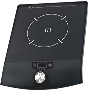 Sold in the UK by Maplin, has power levels adjustable from 300 watts to 2000 watts, and costs only £30 delivered to your address. These devices operate by generating a powerful high frequency oscillating magnetic field which induces eddy currents in any magnetic material placed on the surface of the cooker. That is, cookware which is made of cast iron or steel (not stainless steel which is supposedly non-magnetic). The heating is very rapid and completely uniform across the item of cookware which is very helpful when cooking. The hot plate is controlled by sophisticated electronics which will not switch on unless there is an iron object on the plate and which varies the frequency and current in a way chosen by the designer. The circuitry produces the magnetic field by pulsing current through a large, flat coil in the centre of the case as can be seen in this photograph of a typical induction plate with the case opened: 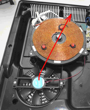 The brown coil gets hot, and so there are spacers on it to prevent the cool outer casing form picking up the heat of the coil. There is also a fan which draws air in from underneath the case and blows it across the coil in order to keep the heat down. In order to use this magnetic transmitter, we need to place a suitable output coil on the plate, and power a load from the energy collected by that coil. This is a fairly recent idea and so there is still a good deal of experimentation going on, testing different coils, and various loads. It is generally agreed that the best load is a non-inductive load with halogen lamps and ordinary filament light bulbs being recommended. Halogen lamps are used in some low-cost commercial heaters, and they are very effective method of radiant heating. In his video at http://www.youtube.com/watch?v=LbAhUwHvJCE, Laurent powers seven separate 400-watt halogen lamps using a small 800-watt maximum plate which has a small 120 mm diameter transmitter coil: 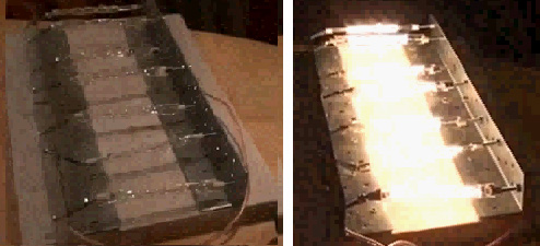 No particular power output is claimed by Laurent, but as you can see, the 2800 watts of halogen lamps are brightly lit while a wattmeter on the input to the plate reads just 758 watts. It seems to be fairly clear that there is a significant power gain with this arrangement. Then, Laurent places an additional coil on top of the first one and shows it lighting a 100-watt filament light bulb very brightly:  It is actually quite difficult to see the brightness of lamps shown in a video as the video camera automatically turns down the brightness of the recording. The important point here is that there is significant power output from a second coil, without there being any increase in the power input to the transmitter coil in the induction plate. There are many different designs of electronics in commercial induction plates. Most will not start operating until a magnetic object is placed on top of the plate. If that is done, then the object needs to be removed very promptly as it heats up very rapidly. Fortunately, most plate designs keep operating as soon as the induction process is started and so there in no problem with removing the metal cookware (or whatever is used to start the process). Laurent’s very small induction plate does not have that protection circuitry and so starts up as soon as it is switched on. Jean-Louis Naudin uses a 2000-watt induction plate turned down to its 1000-watt setting. It has a 180 mm diameter pick-up coil. He says that for him, it is essential to have at least 1500-watts of load or else the induction plate will shut down with an error code indicating that no cookware is present. The coils used are Tesla bi-filar pancake types, typically, attached to a thin sheet of MDF or plywood, say 2 mm thick, with superglue. Laurent’s 120 mm coil has ten turns and Jean-Louis’ 160 mm coil has sixteen turns, needing about 5 metres of twin-core wire, and Laurent’s about 2.5 metres of wire. I suggest that the wire should be rated for mains voltage and have, perhaps 1 sq. mm cross-sectional area of copper wire in each conductor. A Tesla pancake coil is wound like this:  Please remember that this arrangement involves high voltages and so is not suitable for newcomers to electronics. This presentation is strictly for information purposes only and it is not a recommendation that you attempt to implement anything shown here, and if you choose to do so, then the responsibility is yours and yours alone. An interesting video is here. Tariel Kapanadze Tariel appears to have based his work on that of Nikola Tesla. There has been a video on the web, of one of his devices in operation, but it appears that the video has been removed. However, part of it can be seen here. The video commentary was not in English and so the information gathered from it is not as complete as it might be. However, in spite of that, a number of useful things can be learned from it.  The video shows a demonstration being staged in a back garden, I believe, in Turkey. Strong sunshine was casting dense shadows which made video detail less than perfect. Essentially, Tariel demonstrated one of his builds of a Tesla-style free-energy device, powering both itself and a row of five light bulbs. One of the most encouraging things about this video is that the construction and operation was of the most basic kind, with not the slightest suggestion of expensive laboratory work or anything high-precision. This is most definitely a backyard construction within the scope of any knowledgeable person. Electrical connections were made by twisting bare wires together: 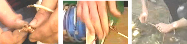 and where necessary, tightening the twist with a pair of pliars: 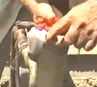 This shows clearly that a high-power and very useful free-energy device can be made with the most simple of construction methods - no expensive connectors here, just a zero-cost twisted connection. 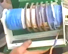 The device being displayed is a Tesla Coil powered, earth-connected system of the type already described. You will notice that the thick primary winding is not placed at one end of the central secondary winding but is much closer to the centre of the coil. Remember that Don Smith states that if the primary coil is placed centrally, then the amount of current which the coil can deliver is very large, in spite of the fact that most people think that a Tesla Coil can only produce trivial currents. Notice also that this Tesla Coil appears to be mounted on a cheap kitchen-roll holder. I have seen it said that Tariel makes a new device for each demonstration and takes it apart afterwards, so if that is correct, then it is likely that there is no great effort or expense involved in making one of these systems. 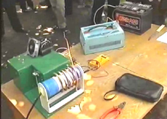 The main operational components are shown here, placed on one small table. There is a lead-acid battery (which is removed later in the demonstration), what appears to be an inverter to produce mains AC voltage from the battery, a high-voltage step-up system housed in a green box for safety reasons, a Tesla Coil, a spark gap mounted on the box and a fan-cooled component, probably a solid-state oscillator system driving the Tesla Coil. Not seen in this picture, is an item contained in a small box which might well be a high-voltage capacitor. Two earth connections are organised. The first one is an old car radiator buried in the ground:  and the second is a bare wire wrapped around a garden tap's metal pipe and twisted tight as shown above. It is distinctly possible that the circuit is based on this circuit of Tesla's:  Perhaps, the battery powers the inverter which produces mains voltage, which is then stepped up to a high voltage level by the enclosed electronics. This then drives the Tesla Coil, producing both very high voltage and current with the capacitor storing the energy as a reservoir. The spark gap then pulses this energy, driving the primary winding of the isolation transformer which produces a lower voltage at substantial current (depending on the current-handling capacity of the transformer itself) powering the load, which in this case, is a row of light bulbs. The load is a row of five light bulbs hung from a broom placed across the backs of two chairs:  As you can see, this is not exactly high-tech, high-cost construction here, with all of the materials being used for other things afterwards. Initially, the battery is used to power the inverter and it is demonstrated that the current being drawn from the inverter is substantially less than the power entering the load. In conventional terms, this appears impossible, which is an indication that the conventional terms are out of date and need to be updated to include the observed facts from demonstrations such as this. As the system is putting out a good deal more power than is required to drive it, might it not be possible to use part of the output power to provide the input power. This is often called "closing the loop" and it is demonstrated in this video as the next step. First, the circuit is altered so that the input power connection to the inverter is taken from the output. Then the circuit is powered up using the battery as before. The battery is then disconnected and removed altogether, and the people helping with the demonstration pick up all of the active items and hold them up in the air so as to show that there are no hidden wires providing the extra power from some hidden source. The items on the table are not part of the circuit: 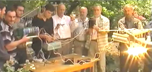 There is some additional information on Tariel including videos of some of his more powerful, newer designs at this website although it has to be said that there does not appear to be very much on him or his work available at this time. In December 2009 an anonymous contributor e-mailed to say that Kapanadze returned to the ex-USSR republic of Georgia and that the video soundtrack is in the Georgian language and after the demonstration, the interview is in Russian. He has kindly translated the parts which relate to the device, as follows: Question: What are you showing us today? Answer: This is a device which draws energy from the environment. It draws 40 watts as it starts up, but then it can power itself and provide an output of 5 kilowatts. We don't know how much energy can be drawn from the environment, but in an earlier test, we drew 200 kilowatts of power. Question: Is it possible to solve the energy problems of Georgia? Answer: We consider that they have already been solved. Question: Please tell us in simple terms, how your device works. Answer: (1) Power is drawn from the battery to get the device running (2) If we want, we can use part of the output power to drive a charger and charge the battery (3) When the device is running, we can remove the battery and it then operates self-powered. This particular unit can deliver 5 kilowatts of power which is enough for a family. We can easily make a version which supplies 10 kilowatts. We don't know what the practical power limit is for a unit like this. With this particular device we have here, we do not draw more than 5 kilowatts as we don't want to burn out the components which we used in this build. Question: Does your invention pick up current from mains wires? Answer: The mains has nothing to do with this device. The energy produced comes directly from the environment. Question: What do you call your device and do you dedicate it to anyone? Answer: I would not dream of claiming this device to be my invention, I just found something which works. This is an invention of Nikola Tesla and all the credit is his. Tesla has done so much for mankind but today he is just forgotten. This device is his invention, his work. Question: Why are you so sure that this is a design of Nikola Tesla's? Answer: Because I worked from his invention - his design. I discovered how to get automatic resonance between the primary and secondary windings. The most important thing is to achieve resonance. Melnichenko came close to solving this problem. The government of Georgia refuses to take this invention seriously. Question: You said that resonance must be maintained. Which parts resonate? Answer: Here (pointing to the green box) and here (pointing to the Tesla Coil mounted on the top of the green box). The resonator is inside the green box and at present, it is secret until patented. Question: How much would one of these units cost? Answer: When mass produced, it would cost between 300 and 400 US dollars for a unit which has an output of 5 or 6 kilowatts. Question:How much did it cost you to build this demonstration device? Answer: About eight thousand (currency not specified, but the previous question was US dollars). Parts had to be got in from twenty different places. Question: Is this your house? Answer: No, I rent this place because we have sold all that we have to make these devices. And, having done it, the government and many scientists say "We are not interested because a device like that is impossible and can't possibly exist!". I have not been allowed to make a presentation to them, but people who understand the Tesla Coil understand how this device works. Kapanadze is an architect by profession and has not had any training in either physics or Electrical Engineering. The information on which this design was based was downloaded free from the internet. One of the most important aspects of this video is the confirmation it gives for the work of Tesla and of Don Smith, in that it shows clearly, yet again, that large amounts of energy can be drawn from the local environment, without the need to burn a fuel. Another video can be seen here. People frequently ask for construction drawings or alternatively, outlets where they can buy one of his devices. Unfortunately, Tariel is not willing to share the details of his designs and so they will probably never be manufactured. Many people have tried to analyse and replicate his design. Kapanadze Analysis by William McFreey Shown below are two analysis papers on Tariel Kapanadze’s designs. These papers by William McFreey are written primarily for physiscts, and so they may not be easily understood by you if you are not familiar with scientific symbols and notation. While William McFreey’s paper is highly technical, the designs disclosed in it have been prototyped and proved to be fully functional. However, it needs to be understood that there are several ways of extracting free-energy from our local environment. For example:
The Cold Electricity Coil of ‘UFOpolitics’. A man who uses the forum ID of ‘UFOpolitics’ has been sharing his insights and experiences on various different forums, such as the one dealing directly with the production and use of cold electricity in solid-state circuits: forum His insights are unusual and very important. His basic statement is that if a coil is pulsed, using a circuit like this:  then conventional hot electricity pulses the coil when the transistor is switched ON, but if that current is switched OFF rapidly, then there is an inflow of cold electricity into the coil from the surrounding environment. That inflow of energy can be collected and diverted to power a load through the use of two high-speed diodes which can carry considerable current as the power inflow is substantial. The inflow of energy occurs when the transistor is switched OFF and so it is desirable to have the transistor switched off for most of the time, in other words, a low percentage Duty Cycle for the transistor. There MUST be a significant load on the cold electricity output. If there is not, then the cold electricity will flow back into the hot electricity section of the circuit and it may damage the transistors. Tom Bearden states that resistors boost cold electricity rather than hindering it’s flow, so the load should be a coil, a DC motor with brushes or a fluorescent light bulb. It has been observed that the incoming energy tends to flow inwards towards the centre of the coil, so an additional method of collecting this extra energy is to place a second coil inside the main coil, and wound in the same direction as it, like this:  This provides two separate, independent cold electricity power outputs. Diodes are not needed for the inner ‘secondary’ coil. This inner coil is a pick-up coil and is not related in any way to the number of turns in the hot electricity pulsing coil. Instead, this coil collects inflowing cold electricity during the period when the pulsing coil is switched OFF. The hot electricity pulsing coil can be wound directly on top of the extra pick-up coil or the extra coil can be wound separately and placed inside the main coil spool. Very surprisingly, it is recommended that the powerful high-speed diode used to channel the cold electricity out of the circuit, be followed by a small 1N4148 silicon epitaxial planar high-speed diode (75V 0.45A) as this is said to clean up the cold electricity output even more. It is important that the cold electricity has to encounter the more powerful silicon diodes before reaching the 1N4148 diodes, so the order of the diodes is very important, and should be as shown here:  Alternative diodes for the NTE576 (6A, 35nS, 400V) are the NTE577 (5A, 70nS, 1000V) and the HFA16PB (16A, 19nS, 600V). The main requirement is high-speed operation, voltage rating of at least 400V and current rating of at least 5 amps.. There is one additional thing to be done with this circuit when a DC output is required and that is to apply filtering to the output. First, when the energy has passed through the NTE576 (or equivalent) power diodes, it encounters a high-frequency (low capacity) high quality film capacitor placed across the output in order to siphon off any high-frequency voltage ripple before it is passed through the small 1N4148 diodes and into a smoothing and storage electrolytic capacitor. Storing the cold electricity in the electrolytic capacitor converts it into conventional hot electricity.  While this circuit looks like something which you just switch on and it works, that is not the case as there is an essential start-up procedure where the signal applied to the transistor is started at just a few cycles per second and 50% duty cycle and that input is then adjusted carefully and slowly while monitoring the voltages and currents produced by the circuit. This is a seriously powerful system with the capability of producing a major power output.  It is very important that the circuit is not powered up without a suitable load on the cold electricity output. A suitable load is a self-ballasted 230-volt fluorescent light. It must be understood that just flipping the power switch to it’s ON position is not sufficient to get an inflow of cold electricity. Instead, it is necessary to progress the start-up sequence carefully, and a fluorescent light is particularly helpful for doing this although a neon bulb is also a popular choice of temporary load, because these devices allow the current flow in the load to be assessed visually. Before switch-on, the input oscillator is set to 50% duty cycle and minimum frequency. Then the frequency is raised very slowly, causing the lamp to start flashing. As the frequency is raised, the current drawn from the battery needs to be monitored as it is the current flowing through the transistor, and the current is kept down by lowering the duty cycle progressively. This process is continued carefully and if successful, the colour of the light produced will initially be purple or green before reaching continuous bright white light. Videos showing the light produced and the fact that it is not dangerous to life or affected by water can be seen here. The driving force is a series of powerful magnetic pulses, and implementing the physical circuit to achieve that requires careful construction. The battery driving the circuit is a 36 volt combination of cells. The coil is wound as an air-core construction on a 2-inch (50 mm) diameter spool and the DC resistance is arranged to be about 1.4 or 1.5 ohms. This, in turn, requires a substantial drive from the transistor and so it is normal to connect six powerful output transistors in parallel in order to spread the current flow between them as well as dissipating the heat generated across several transistors bolted to a common heat-sink of generous area. How the coil is wound is something to consider. The objective is to have a coil of about 1.5 ohm resistance and which has the maximum magnetic effect for the current passed through it. Copper wire has become very expensive and so it would be very costly to wind the coil with vast lengths of thick wire, not to mention the very large size and great weight which would be produced by doing that. The copper wire options in Europe are typically to work with half-kilogram reels of wire. The details of some of these are as follows:  We can see from this that a 500 gram reel of 14 swg wire has a total resistance of just 0.09 ohms and so it would take sixteen reels (weighing 8 kilograms and costing a lot of money) to wind just a one-strand coil using that wire, producing a coil which cold carry a current of 9.3 amps. As opposed to that, a single reel of 28 swg could provide 52 separate windings, which when connected in parallel, could carry 15 amps as well as costing and weighing far less. It would be tedious, but not impossible, to wind a 52-strand coil, so a more reasonable number of strands connected in parallel might be used. We are aiming at a DC resistance of about 1.45 ohms in any coil arrangement which we select. The magnetic field produced by a single strand is generally less than the magnetic field produced by two strands carrying the same total current. So, if we were to pick 22 swg wire, then we could measure out four 133.5 metre lengths, joint them at the start, and wind the four strands simultaneously, side-by-side to form a coil with a DC resistance of 1.45 ohms. It is important that the strands are exactly the same length so that they carry exactly the same current and no one strand gets overloaded with current due to it having a lower resistance than the other strands. It should be realised that as the maximum current which the wire can carry is 4.8 amps and the resistance is only 1.45 ohms, the maximum continuous DC voltage which can be sustained by the coil is only 7 volts, and so as a 36-volt battery is being used, we must adjust the frequency and duty cycle very carefully, especially since we are starting at very low frequencies. If the full battery voltage is applied continuously to the coil, then the coil will be destroyed. Various members of the forum have suggested, built and tested different circuits for feeding a variable-frequency variable-duty-cycle drive signal to the output transistor. However, ‘UFOpolitics’ recommends a simple 555 timer circuit. If you are not familiar with electronic circuits, then read chapter 12 which explains them in some detail, including the 555 timer family of circuits. The point stressed by ‘UFOpolitics’ is that the output taken from pin 3 of the 555 chip passes first through a 100 ohm resistor and then, every transistor gets a separate feed via a two resistor voltage divider pair. The 47K Gate-to-Ground resistor is to ensure that the FET turns off properly. It my be possible to increase the value of these resistors but they should never be less than 47K.  The thick lines in this diagram indicate heavy-duty wiring which can carry high currents without generating any real heat when doing so. It is also recommended that although the FET has an internal diode, an extra external high-speed diode (NTE576 or similar), be connected across each FET in order to boost the switching speed:  A FET has a gate capacitance of about 1 nF. The faster it can be charged / discharged the faster the FET will switch (and stay cool). What determines the speed of charge / discharge for the gate capacitance is the length of wire from driver to gate or gates = inductance (where one metre of wire produces 0.05µH. In addition to that, different lengths of Gate connection wire will create different switching delays and the different inductances can then initiate High Frequency oscillations with repetitive ON/OFF/ON/OFF switching actions. The result might be burned FETS and lack of cold electricity activities. Another point made by ‘UFOpolitics’ is that the physical layout should have the connecting wires or tracks kept as short as possible and he suggests this layout:  There are two things to note here. Firstly, the 100 ohm resistor coming from pin 3 of the 555 timer IC is positioned centrally around the six FET transistors mounted on the aluminium heat-sink, and that point is carried closer to each FET with a low-resistance conductor to give a good-quality link for the resistors feeding the Gate of each FET. Secondly, the heat-sink itself is also used to provide a low-resistance electrical connection to the coil which the FETs are driving. The connection to the heat-sink is via a nut and bolt clamping a solder tag firmly to a cleaned area of the heat-sink. Each FET is electrically connected to the heat sink through it’s mounting tag which forms it’s heat-sink connection as well as connecting to the Drain of the Transistor. However, if the aluminium heat sink is a black anodised type, then, apart from cleaning between each FET and the heat-sink contact area, it is worth running a thick wire also linking the central FET pins to the output wire connection point. The transistors used in the prototype, and recommended for replications is the NTE2397. This is not a very common transistor in Europe at this time and so the popular IRF740 might perhaps be used as it appears to have all of the main characteristics of the NTE2397 transistor. ‘UFOpolitics’ suggests the 2SK2837 (500V, 20A, 80A pulsed), or the IRFP460 (500V, 0.27 Ohm, 20A and 80A pulsed) As the 555 timer has a maximum supply voltage of 15 volts, an LM317N voltage-stabiliser chip is used to create a 12-volt supply from the 36-volt battery (a 24V battery could be used):  The LM317N integrated circuit should be attached to a good heat sink as it is dropping off 24 of the 36 volts powering the circuit, and so, has to dissipate twice the power that the NE555 chip uses:  There are various pulsing circuits which have been used successfully with this system. ‘UFOpolitics’ considers the NE555 chip to be the most straightforward, so perhaps my suggestion for this arrangement might be a suitable choice:  This gives fine control of the frequency and independent adjustment of the Mark/Space ratio or ‘Duty Cycle’ and it needs only three very cheap components other than the controls. If the expensive multi-turn high quality variable resistors are available, then the 4.7K ‘fine-tune’ variable resistor can be omitted as those variable resistors make the adjustments easier to control. The ‘Lin.’ In the diagram stands for ‘Linear’ which means that the resistance varies steadily at a constant rate as the shaft of the variable resistor is rotated. In the ‘UFOpolitics’ circuit, it is important to turn the frequency down to it’s minimum value and set the Mark/Space ratio to 50%, before powering the circuit down. Otherwise it would be easy to power the circuit up with a much higher frequency than is advisable and so, causing damage to some of the circuit components. There are ways to boost the performance over what has already been described. One way is to insert a stainless steel core inside the coil. Stainless steel is supposed to be non-magnetic but in practice, that is not always the case. However, ideally, this steel core is improved by altering it’s crystalline structure by heating it up and then quenching it by submerging it in cold water. Another improvement is to isolate the coil better at switch-off through the use of a second transistor. Having a ‘switched-off’ transistor at each end of the coil certainly blocks the flow of hot electricity, but if Tom Bearden is correct, the resistance of the transistors in their OFF state will actually boost the flow of cold electricity as it reacts in the reverse way to how hot electricity reacts. The arrangement is like this:  While this looks like a very simple circuit to implement, that is not the case. The upper transistor is switched ON by the voltage difference between it’s Gate “G” and it‘s Source “S”. But, the voltage at it’s Source is not fixed but varies rapidly due to the changing current in the coil, and that does not help when solid and reliable switching of the upper transistor is needed. A P-channel FET could be used instead and that would have it’s Source connected to the fixed voltage of the Plus of the 36V battery. That would help the switching enormously, but there would still be timing issues between the two transistors switching ON and OFF at exactly the same time. Other circuits have been suggested for doing that type of switching, but in the early stages, ‘UFOpolitics’ recommends that things be kept as simple as possible, so using just one transistor (although, perhaps, a bank of six in parallel to boost the current handling) is the best option. Switching speed is an item of major importance, even to the extent that the reduction in the speed of switching caused by using more than one transistor in parallel has caused the suggestion to be made that it might actually be a better option to use just one FET since these high-performance FETs are capable of carrying the whole of the switching current, and it is mainly to lower the FET operating temperature that multiple FET use is suggested. Every extra FET used in parallel, slows the switching down. However, it should be realised that there is a somewhat greater risk of burning the FET out if just one is used. The coil dimensions recommended are two-inch (50 mm) diameter and 2-inch length. The wound coil is likely to be about three-inches (75 mm) so making the flange diameter 4-inches (100 mm) is realistic:  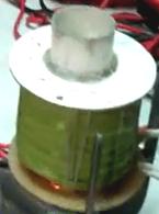 The recommended material is fibreglass which has high heat-resisting properties as well as being easy to work, the personal choice of ‘UFOpolitics’ is Polyester Resin with Methyl Ethyl Kethol (MEK) Hardener. A suggested alternative is acrylic, which is not as heat resistant. Acrylic is excellent for high-frequency applications but this circuitry does not operate at high frequencies. Whatever spool material is chosen, it needs to be non-magnetic. When connected in the circuit, the start of the coil winding wire goes to the battery positive. Here is another coil wound on acrylic tube and with all four diodes connected to the ends of the coil: 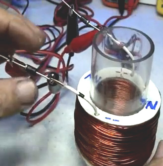 It should be understood that cold electricity provides almost unlimited power and it has uses which are not readily understood by many people. ‘UFOpolitics’ suggests that the hot electricity drive circuitry be tested initially using just a resistive load. If everything checks out correctly, then test with a lesser value resistor in series with the coil, and if that checks out satisfactorily, then testing cautiously with the coil on it’s own. Cold electricity can charge batteries rapidly and after a series of charge and discharge cycles, batteries become ‘conditioned’ to cold electricity and the experiences of Electrodyne Corp. staff show that large conditioned batteries which are fully discharged, can be recharged in under one minute. A member of the present forum has tried this with the ‘UFOpolitics’ circuit and he reports: Yesterday a friend and I took 6 identical, old, 12V, 115Ah batteries and made two 36V banks. We set up bank “A” (the better three) to power the device to charge bank “B”. Bank A was 37.00v at rest and Bank B was 34.94V. My lowest frequency was 133Hz (I need to change my cap and add another 100k pot with the one which is controlling the frequency) and the duty cycle was at 13%. We started at 2A draw on the Primary circuit. As I raised the frequency, the batteries on charge jumped up to 38.4V then dropped evenly to 36.27V and started up again (at about 0.01V every 2 seconds). After 2 and a half hours, they were up to 39.94V. At this point we stopped the charging and let everything rest for 10 minutes. So far everything seems very normal for this kind of charging, except that the device appears to be very stable and powerful...pushing the batteries right on up continuously. The Primary battery voltage dropped initially to 36.20V and stayed there the whole time, then recovered to 36.98V during the 10 minute rest. Then we switched battery banks A and B and charged the opposite way for about 20 minutes. We stopped and rested things again, swapped the banks back and started charging bank B again for another 20 minutes and stopped. After letting the batteries rest for a few hours in order to get truer readings, bank A was at. 37.07 and bank B was at 38.32V. Both battery banks had gained power. These were not very good batteries, either. One of the bank B batteries was at 10.69V at the start. Another interesting note: The amp draw on the Primary dropped from 2A to 1.5A as the frequency was raised from 133Hz to about 550Hz. This was with the very first use of cold electricity with these low-grade batteries and a major improvement can be expected after many additional charge/discharge cycles. This completely overcomes the factors which make a battery bank unsuitable for household power. If an entire battery bank can be recharged in just minutes, then it opens the way for serious household power using a battery bank. Cold electricity can also run motors very powerfully. Forum member ‘Netica’ found that putting a capacitor across the motor terminals improved the running very substantially, giving impressive performance. His video of this is here and the motor, running off an air-core coil with no steel insert. His set-up looks like this: 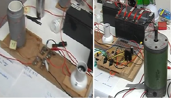 It is also possible to submerge cold electricity circuits in water without causing any harm: 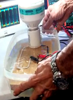  A video of this is located here including demonstrating the use of very powerful light bulbs. A general running demonstration is here. Stanley Meyer. Stan, who is famous for his water-splitting and related automotive achievements, actually held about forty patents on a wide range of inventions. Here is one of his patents which circulates magnetic particles in a fluid, and while the fluid does move, none of the other components in the device move and a high level of constructional skills is not called for: Please note that this is a re-worded excerpt from this Stan Meyer patent. Although it does not state it in the patent, Stan appears to make it understood that this system produces a significant power gain – something with Patent Offices find very difficult to accept. ELECTRICAL PARTICLE GENERATOR An electrical particle generator comprising a non-magnetic pipe in a closed loop having a substantial amount of magnetised particles encapsulated inside it. A magnetic accelerator assembly is positioned on the pipe, which has an inductive primary winding and a low-voltage input to the winding. A secondary winding is positioned on the pipe opposite to the primary winding. Upon voltage being applied to the primary winding, the magnetised particles are passed through the magnetic accelerator assembly with increased velocity. These accelerated particles passing through the pipe, induce an electrical voltage/current potential as they pass through the secondary winding. The increased secondary voltage is utilised in an amplifier arrangement. BACKGROUND AND PRIOR ART The prior art teachings expound the fundamental principle tat a magnetic field passing through inductive windings will generate a voltage/current or enhance the voltage across it if the winding is a secondary winding. It is also taught by the prior art, that a magnetic element in a primary inductive field will be attracted at one end of the coil and repelled at the other end. That is, a moving magnetic element will be accelerated in motion by the attraction and repulsion of the magnetic field of the primary inductive winding. In the conventional step-up transfer, the voltage across the secondary is a function of the number of turns in the secondary relative to the number of turns in the primary winding. Other factors are the diameter of the wire and whether the core is air or a magnetic material. SUMMARY OF THE INVENTION The present invention utilises the basic principle of the particle accelerator and the principle of inducing a voltage in a secondary winding by passing a magnetic element through it. The structure comprises a primary voltage inductive winding having a magnetic core, plus a low-voltage input. There is a secondary winding with a greater number of turns than the turns in the primary winding, plus an output for using the voltage induced in that winding. The primary winding and core are positioned on one side of an endless, closed-loop, non-magnetic pipe. The secondary windings are positioned on the opposite side of the endless pipe. The pipe is filled with discrete magnetic particles, preferably of a gas, and each particle has a magnetic polarised charge placed on it. Due to their magnetic polarisation charges, the particles will sustain some motion. As the particles approach the accelerator assembly, which is the primary coil, the magnetic field generated by the coil attracts the particles and accelerates them through the coil. As each particles passes through the coil, the repulsion end of the coil boosts the particle on it’s way. This causes each particle to exit from the coil with an increased velocity. As the magnetic particles pass through the secondary coil winding, they induce a voltage across the ends of that coil. Due to the larger number of turns, this induced voltage is much higher than the voltage across the primary coil. The main objective of this invention is to provide an electrical generator which is capable of producing a voltage/current of much greater magnitude than has been possible previously. Another objective is to provide a generator which uses magnetic particles and a magnetic accelerator. Another object is to provide a generator which can control the amplitude of the output. Another objective is to provide a generator which can be used with DC, AC, pulsed or other configurations of waveforms. Another objective is to provide a generator which can be used in either a single-phase or a 3-phase electrical system. Another objective is to provide a generator for developing magnetised particles for use in an electrical particle generator. Another objective is to provide an electrical generator which uses readily available components to construct a simple embodiment of this invention. BRIEF DESCRIPTION OF THE DRAWINGS  Fig.1 is a simplified illustration of the principles of the invention, shown partially in cross-section and partially pictorially.  Fig.2 is an electrical schematic illustration of the embodiment shown in Fig.1.  Fig.3 is an illustration similar to Fig.2 but which is adaptable to 3-phase use.  Fig.4 is a first alternative arrangement of a preferred implementation of the invention.  Fig.5 is another alternative arrangement of a preferred embodiment of the invention.  Fig.6 is another alternative arrangement of a preferred embodiment of this invention.  Fig.7 is another alternative arrangement of a preferred embodiment of this invention.  Fig.8 is another alternative arrangement of a preferred embodiment of this invention.  Fig.9 is an alternative arrangement for a magnetic drive particle accelerator assembly.  Fig.10 is an illustration of an alternative method of producing the magnetised particles used in this invention. DETAILED DESCRIPTION Fig.1 and Fig.2 show the invention in it’s most simplified schematic form:  It comprises a primary coil magnetic accelerator assembly 10, a closed-loop non-magnetic pipe 30, and a secondary winding 20. The magnetic accelerator assembly is comprised of primary windings 12, a magnetic core 14, and voltage taps 16. The primary windings are positioned around end 32 of the closed-loop pipe 30 which is made from non-magnetic tubing. At the opposite end 34 of the closed-loop pipe 30, are the secondary windings 20. The end terminals 22 of the secondary winding 20, allow the voltage generated in the winding to be used. Contained inside pipe 30, there is a substantial number of magnetic particles 40 as shown in Fig.2. The particles 40 must be light enough to be freely mobile and so may be particles suspended in a fluid medium such as gas, liquid or light-weight movable solid particles. Of these options, the use of a gas is preferred. If solid particles are used as the transporting medium, then it may be desirable to remove all air from inside the pipe in order to reduce the resistance to the flowing particles. Each of the particles 40 is magnetised and the following description refers to one individual particle and not to the mass of particles as a whole. The voltage applied to terminals 16 of primary winding 12, is a low voltage, and it’s magnitude may be used as an input signal control. By varying the input voltage, the accelerator will vary the speed of the circulating particles, which will, in turn, vary the magnitude of the voltage/current output of the secondary winding 20. The output 22 of the secondary transformer winding 20, is a high voltage/current output. It can be appreciated that the system shown in Fig.1 and Fig.2 where there is just one closed loop, provides a single-phase output in the secondary winding 20. Fig.3 shows a closed-loop arrangement with three parallel non-magnetic tubes 31, 33 and 35, each with it’s own output winding 21, 23 and 25. Each of these three windings are a single-phase output, and as their three pipes share a common input junction and a common output junction, these three output windings provide a balanced 3-phase electrical system. Fig.4 shows an electrical power generator which operates exactly the same as those shown in Fig.1 and Fig.2. Here, the arrangement is for use in an environment where there is a high moisture content. An insulating coating 45, completely covers pipe 30 as well as all of the electrical windings. Fig.4 also illustrates the fact that increasing the number of turns for any given wire diameter increases the voltage/current output of the device. In this physical configuration, both vertical and horizontal directions are used which allows a large-diameter pipe to be used with a substantial number of turns of heavy-gauge high-current wire. Fig.5 shows a coil arrangement 49, which uses the entire magnetic flux in the closed-loop tubing 47. This is a co-axial arrangement with the primary winding 43 as a central core. Fig.6 illustrates a concentric spiral configuration of the tubing 50, with the secondary windings 53 covering it completely. Fig.7 shows an arrangement where the particle accelerator 10 is wound over the tubing 30 in much the same way as in Fig.1 and Fig.2. However, in this arrangement, the tubing 30 is a continuous closed loop arranged in a series-parallel configuration where there are three secondary windings providing three separate outputs while the tubing 30 runs in series through those three windings. Fig.8 shows a configuration which is the reverse of that shown in Fig.7. Here, there are several pick-up coils wound in series and unlike the earlier configurations, the tubing 80 is not continuous. In this arrangement, there is an input manifold 82, and an output manifold 84, and several separate tubes 60a, 60b, 60c, ….. 60n interconnecting those two manifolds. Each of those separate tubes has it’s own separate secondary coil 70a, 70b, 70c, ….. 70n wound on it. The magnetic particle accelerator 10, can be different in design to that shown in Fig.1. Fig.9 shows a mechanical particle accelerator 100. In this arrangement, the magnetic particles 102 are permanently magnetised prior to being encapsulated in the non-magnetic pipe 110. The particles 102 are accelerated by fan blade or pump 104 rotated by mechanical drive assembly 106. The mechanical drive for assembly 106 may be a belt-drive pulley 112, or similar device driven by an electric motor. A sealing bearing 114 keeps the particles 102 inside the pipe 110. It has been stated that the magnetic particles traversing the secondary coils, generate a voltage/current in them. It must be understood, however, that that the particles are actually traversing the magnetic field of those coils. Also, the pipe 30 has been described as a non-magnetic pipe. There are certain non-magnetic pipes which would not work with this invention. Pipe 30 must be capable of passing magnetic lines of force. A significant feature of each of the various embodiments already described, is the generation of the magnetic particles which are encapsulated within the tubing. Fig.10 shows an apparatus for carrying out the process of vapourising material to produce suitable particles which are then magnetised by being subjected to a magnetic field. The chamber 155 is an evacuated chamber having electrodes, made from magnetisable metal, 160 and 162. A voltage is applied between terminals 150 and 152, and this drives a current through terminals 154 and 156, to spark-gap electrodes 160 and 162, generating an arc which vapourises the tip material of the electrodes, producing particles 180. These particles rise and enter tube 190, passing through a magnetic field generator 175. This gives each particle a magnetic charge and they continue on their way as magnetically-charged particles 185, passing through port 190 to reach the electrical particle generator described above. In the simplified embodiment shown in Fig.1 and Fig.2, as well as the other preferred embodiments mentioned, it was indicated that a low voltage was applied to the particle accelerator 10. Upon acceleration, a high voltage/current would be induced in the secondary pick-up coil 20. A most significant advantage of the present invention is that the voltage amplification is not related to the shape of the waveform of the input voltage. Specifically, if the input is DC a DC voltage will be output. An AC input will produce an AC output. A pulsed voltage input will produce a pulsed voltage output and an input voltage of any other configuration will produce an output having that same configuration. Russ Gries Russ has produced a video presentation and analysis of the above Stan Meyer patent. This is a large download file which takes a considerable time to receive (some hours in my case). The download link is 1: Video 1 2: Video 2 3: Video 3 ……. 8: Video 8 And in particular, video 8, where Stan discusses the design and use of the generator. It is easy to get somewhat confused as Stan talks about both the Electrical Particle Generator and it’s use in combination with HHO production as a large-scale power generation source. The very experienced Alex Petty is joining with Russ in working on replicating Stan’s system and Alex’s web site is www.alexpetty.com. A discussion forum linked to this is here and there is information here at www.overunity.com and high-resolution pictures can also be seen in Russ’ video here. Russ’ own website is here and an additional video of the most recent developmental work being undertaken is here. There are various important things which are commented on and Russ is to be commended for drawing attention to them. For the moment, please forget about HHO as that is a separate issue. As far as I can see, the patent does not claim that the device is COP>1 but instead that the device is a power transformer which potentially has a greater power output than conventional transformers since there is no Lenz Law reverse magnetic path from the output coil winding to affect the input power. Having said that, Stan in his video points out ways to boost the power of the device, namely: 1. Increase the strength of the magnetic particles 2. Increase the speed of the magnetic particles 3. Lower the distance between the magnetic particles and the output winding. The magnetic particles can be produced in various ways, but the most effective appears to be by filling the arcing chamber with argon gas and using iron, nickel or cobalt electrodes. The reason for this is that the electric arc does not only generate minute particles of the electrode material, but it also interacts with the argon, stripping off electrons and causing some of the metal particles to combine with the modified argon gas molecules to form a magnetic gas. That gas will always remain a magnetic gas due to the atomic bonding as it is not just minute particles of metal physically suspended in a gas due to their tiny size. You will recall from chapter 1, that the very successful ShenHe Wang magnet motor/generator has a magnetic liquid as a key component. Here, Stan is producing a much lighter magnetic gas and the advantage of that lightness is that it can be boosted to very high speeds without any danger. The larger the number of modified argon molecules, the greater the magnetic effect when they pass through a coil of wire. The argon gas can be passed through the arc chamber over and over again so that a very high percentage of the gas is magnetic. Alternatively, if you are sophisticated in the design of the particle generator, you can arrange for the molecules which have become magnetic, to be pulled off into storage by a magnetic field. Stan talks about pumping the magnetic gas through whatever pipe loop arrangement you decide to use, by a pump, but he promptly moves on to using a magnetic coil to boost the gas forward as the coil has no moving parts and so, no mechanical wear. This is only one reason. The main reason is that with magnetic acceleration, the gas speed can become very high indeed and in his video he talks about the speed of light. However, I personally do not believe that anything remotely like a speed that great could be achieved inside a pipe loop of small diameter. Nevertheless, speeds well in excess of what a mechanical pump can achieve are likely to be produced by magnetic acceleration. Russ, in his discussion, points out that on most of Stan’s surviving prototypes, the coil which is used for the acceleration is constructed using several apparently separate coils, and he speculates that each coil section is powered sequentially, causing a rippling magnetic field. While that is definitely possible, I don’t see that a style of coil powering would have any advantage as opposed to powering all of the coils continuously. However, if sequential powering is believed to be an advantage, then the ‘Divide-by-N’ circuitry of chapter 12 can be used to provide the sequential powering or any more complex sequence. Stan then points out that the output voltage can be increased by increasing the number of turns on the output coil and/or having additional output coils. This is easily understood conventional electrics. But, he then goes on to point out that the output will also be increased if the electrons of the modified argon molecules are raised to a high orbital level. This places the electromagnetic electrons (as described in chapter 11) closer to the output coils and presumably also allows the gas to be accelerated to a greater speed by the driving magnetic field. This power boosting of the gas is achieved using Stan’s “Gas Processor” described in chapter 10. The Gas Processor pumps electromagnetic energy into the gas through the use of banks of Light-Emitting Diodes which produce light of the correct wavelength to add energy to that particular gas. If you check on the internet for the wavelength of argon, you find conflicting information, with some sites saying that the wavelength is 1090 nanometres (“nm”) and most others saying both 488 nm and 514.5 nm. Most LEDs produce a band of frequencies, so it would be a case of picking LEDs whose band of frequencies include the wanted wavelength. The Gas Processor itself, consists of a central tube which is polished to a mirror finish on the outside, surrounded by a larger tube which is highly polished on the inside. The LED light is then bounced between these polished surfaces until it is absorbed by the gas which is passed through the gap between the two tubes. This is not easy to illustrate, but it might be shown like this:  In Stan’s design, he uses six columns of sixteen LEDs, with each column of LEDs spaced out evenly around the outer tube. So, to boost the Magnetic Particle Generator to greater power levels, a Gas Processor is placed in the loop of tubing:  The Gas Processor normally has a coil mounted at each end and it may be convenient to use coils in those positions as accelerator coils. It may also be an advantage to apply a pulsed high-voltage between the inner and outer tubes of the Gas Processor. As it stands, this looks as if it has a high possibility of being a COP>1 electrical device. Patrick Kelly http://www.free-energy-info.tuks.nl http://www.free-energy-info.com http://www.free-energy-info.co.uk http://www.free-energy-devices.com |