|
Note: If you are not at all familiar with basic electronics, you might find it easier to understand this chapter if you read chapter 12 first.
There are three categories of pulsed system and we will consider each in turn. These are drive-pulsed systems, energy-tapping pulsed systems and gravity free-energy pulsing systems. Here we will look at systems where an electrical pulse is used to cause the device to operate by creating a temporary magnetic field caused by electric current flowing through a coil or “electromagnet” as it is often called. Many of these systems are rather subtle in the way that they operate. One very well-known example of this is The Adams Motor. The late Robert Adams, an electrical engineer of New Zealand designed and built an electric motor using permanent magnets on the rotor and pulsed electromagnets on the frame of the motor. He found that the output from his motor exceeded the input power by a large margin (800%).  The diagram of his motor intended to show the basic operating principle is shown here:  If a motor is built like this, then it will most certainly work but it will never reach 100% efficiency let alone exceeding the 100% mark. It is only with a specific configuration which is hardly ever publicised that high performance figures can be achieved. While Robert has shown several different configurations, in order to avoid confusion I will describe and explain just one of them. I am indebted to several of Robert's friends and colleagues for the following information and I should like to express my thanks to them for their help and support in bringing you this information. First and foremost, high performance can only be achieved with the clever use of power collection coils. These coils need to be positioned accurately and their power collection restricted to just a very short arc of operation by connecting them to, and disconnecting them from, the output circuit at just the right instant so that the back EMF generated when the current draw stops, actually contributes to the drive of the rotor, speeding it on it's way and raising the overall efficiency of the motor/generator as a whole. Next, the shape of the magnets used is important as the length to width proportion of the magnet alters the pattern of it's magnetic fields. In direct opposition to the diagram shown above, the magnets need to be much longer than their width (or in the case of cylindrical magnets, much longer than their diameter). Further, a good deal of experimentation has shown that the size and shape of the electromagnets and pick-up coils has a major influence on the performance. The cross-sectional area of the core of the pick-up coils should be four times that of the cross-sectional area of the permanent magnets in the rotor. The reverse is true for the cores of the drive coils as their cores should have a cross-sectional area of just one quarter of the rotor magnet cross-sectional area. Another point which is almost never mentioned is the fact that big circuit gains will not be achieved unless the drive voltage is high. The minimum should be 48 volts but the higher the voltage, the greater the energy gain, so voltages in the 120 volts (rectified US mains voltage) to 230 volts (rectified mains voltage elsewhere) should be considered. Neodymium magnets are not recommended for drive voltages under 120 volts. There are several important steps in the way that the Robert Adams motor/generator works and it is important for you to understand each of the steps. Step 1: A rotor magnet is attracted to the iron core of a stator “drive” electromagnet. As it approaches the drive electromagnet, the lines of magnetic force from the stator magnet move across the drive electromagnet coil. This generates an electric current in the drive electromagnet coil and that current is fed back to the battery which is powering the motor/generator:  Notice that the movement of the rotor is caused by the permanent magnets being attracted to the iron cores of the drive electromagnets and not by any electric current. The electric flow is going back into the battery and is being caused by the movement of the rotor which in turn is being caused by the permanent magnets. Step 2: When the rotor turns far enough, the magnets align exactly with the cores of the drive electromagnets. The rotor continues to rotate because of its inertia, but if we do nothing about it, the rotor magnet attraction to the drive electromagnet core will act to slow it down and then drag it back to the drive coil core. We want to prevent that, so we feed a small amount of current into the drive electromagnet coils – just enough current to stop the backward drag of the rotor magnets. This current is NOT to push the rotor magnets away, it is just enough to prevent the rotor being slowed down:  Step 3: When the rotor magnet has moved away far enough, the current being fed to the drive electromagnets is cut off. As happens with any coil, when the current is cut off a large reverse voltage spike is generated. That voltage spike is rectified and fed back to the battery. The system so far produces a spinning rotor for very little current draw from the battery. But we want the system to provide us with excess electrical output, so for that, four additional electromagnets are added around the rotor. These output coils are mounted on a non-magnetic disc which can be rotated to adjust the gap between the drive coils and the output coils. Like the rotor magnets, the output coils are spaced evenly around the circumference of the rotor at 90-degree intervals:  Step 4: Surprisingly, the output coils are switched Off for most of the time. This sounds mad but it most definitely isn’t mad. With the output coils disconnected, the approaching rotor magnets generate a voltage in the output coil windings but no current can flow. As no current is flowing, no magnetic field is generated and so the rotor magnets just pull directly towards the output coil iron cores. The maximum output coil voltage is when the rotor magnets are aligned with the output coil cores. At that instant the output switch is closed and a strong pulse of current is drawn off and then the switch is opened again, cutting off the output current. The output switch is closed for only three degrees or so of the rotor’s rotation and it is off again for the next eighty seven degrees, but the opening of the switch has a major effect. The switch being opened cuts off the current flowing in the output coils and that causes a major reverse voltage spike causing a major magnetic field which pushes the rotor on its way. That voltage spike is rectified and passed back to the battery. The rectification of every possible spare voltage pulse as described, returns 95% of the drive current to the battery, making this an extremely effective motor/generator. The performance can be further enhanced by rotating the set of output coils to find their optimum position and then locking the disc in place. When properly set up, this generator has an output current which is eight times greater than the input current. Notice that the cores of the "generator" pick-up coils are very much wider than the cores of the drive coils. Also notice the proportions of the magnets where the length is much greater than the width or diameter. The four generator windings are mounted on a single disc allowing them to be moved through an angle to find the optimum operating position before being locked in position and the two drive coils are mounted separately and held clear of the disc. Notice also that the power pick-up coils are much wider compared to their length than the drive coils are. This is a practical feature which is explained in greater detail later. The DC input is shown passing through Robert's custom-made contactor switch which is mounted directly on the shaft of the motor/generator. This is a mechanical switch which allows an adjustable On / Off ratio, which is known as the "Mark/Space Ratio" or, if the "On" period is of particular interest, the "Duty Cycle". Robert Adams indicates that when the motor is running and has been adjusted to it's optimum performance, then the Mark/Space ratio should be adjusted to minimise the On period and ideally get it down to about 25% so that for three quarters of the time, the input power is actually switched off. There are various ways of achieving this switching while still having a very sharp turn on and turn off of the power. Robert considered mechanical switching of the drive current to be a very good option although he was not opposed to using the contact to power a transistor to do the actual switching and so reduce the current through the mechanical contacts by a major factor. His reasons for his preference for mechanical switching are that it gives very sharp switching, needs no electrical power to make it operate and it allows current to flow in both directions. The current flow in two directions is important because Robert produced various ways of getting the motor to feed current back into the driving battery, allowing it to drive the motor for long periods without lowering its voltage hardly at all. His preferred method of switching is shown here:   This switching gear operates as follows: The timing disk is bolted securely to the drive shaft of the motor and its position is set so that the electrical switch-on occurs when the rotor magnet is exactly aligned with the drive coil core. Adjustment of that timing is done by loosening the locking nut, rotating the disc very slightly and clamping the disc in position again. A spring washer is used to keep the assembly tight when the device is running. The disc has a star-shaped piece of copper sheet set into its surface and two silver-tipped, copper arm "brushes" slide across the surface of the copper star. One of these two brushes is fixed in position and slides across the copper star near the drive shaft, making a permanent electrical connection to it. The second brush slides alternatively on the non-conducting surface of the disc and then over the conducting arm of the copper. The second brush is mounted so that its position can be adjusted and, because the copper arms taper, that alters the ratio of the "On" time to the "Off" time. The actual switching is achieved by current flowing through the first brush, through the copper arm and then through the second brush. The brush arms shown in the diagram above rely on the springiness of the copper arm to make a good brush-to-copper electrical connection. It might be preferred to use a rigid brush arm, pivot it and use a spring to ensure a very good contact between the brush and the copper star at all times. The adjustment of the On to Off time, or "Mark/Space Ratio" or "Duty Cycle" as the technical people describe it, could perhaps do with some description. If the moveable brush is positioned near the centre of the disc, then, because of the tapering of the copper arms, the part of the non-conducting disc that it slides over is shorter and the part of the conducting copper arm with which it connects is longer, as the two sliding paths are about the same length, the current is on for about the same length as it is off, giving a Mark/Space ratio of about 50% as shown here:  If, instead, the moveable brush is positioned near the outside edge of the disc, then because of the tapering of the copper arm, the On path is shorter and the non-conducting Off path is very much longer, being about three times as long as the On path, giving a Mark/Space ratio of about 25%. As the moveable brush can be positioned anywhere between these two extremes, the Mark/Space ratio can be set to any value from 25% to 50%.  The two brushes can be on the same side of the drive shaft or on opposite sides as shown. One important feature is that the brushes touch in a position where the disc surface is always moving directly away from the brush mounting, causing any drag to be directly along the arm and giving no sideways loading on the brush. The diameter of the device is usually one inch (25 mm) or less. You will also notice that the output is switched although the diagram does not give any indication of how or when that switching takes place. You will notice that the diagram has angles marked on it for the optimum positioning of the pick-up coils, well, an Adams Motor builder with a forum ID of "Maimariati" who achieved a Coefficient Of Performance of 1,223, found that the optimum switching for his motor is On at 42 degrees and Off at 44.7 degrees. That tiny 2.7 degree part of the rotor turn gives a substantial power output and cutting the output current off at that point causes the back EMF of the coils to give the rotor a substantial additional boost on its way. His input power is 27.6 watts and his output power is 33.78 kilowatts Now for some practical details. It is suggested that a good length for the power pick-up coils can be determined by using the “paper clip test”. This is done by taking one of the permanent magnets used in the rotor, and measuring the distance at which that magnet just begins to lift one end of a 32 mm (1.25 inch) paper clip off the table. The optimum length of each coil from end to end is exactly the same as the distance at which the paper clip starts to lift.  The core material used in the electromagnets can be of various different types including advanced materials and alloys such as ‘Somalloy’ or 'Metglas'. The power pick-up coil proportions are important as an electromagnet becomes less and less effective as its length increases, and eventually, the part furthest from the active end can actually be a hindrance to the effective operation. A good coil shape is one which you would not expect, with the coil width being, perhaps 50% greater than the coil length: Contrary to what you would expect, the device draws in energy from the local environment better if the end of the pick-up coil farthest from the rotor is left unaffected by any other part of the device and the same applies to the magnet facing it. That is, the coil should have the rotor at one end and nothing at the other end, that is, no second rotor behind the coil. The speed at which the voltage is applied to, and removed from, the coils is very important. With very sharp voltage rises and falls, additional energy is drawn from the surrounding environmental energy field. If using transistor switching, then the IRF3205 FET has been found to be very good and a suitable driver for the FET is the MC34151. If using a Hall-effect semiconductor to synchronise the timing, say the UGN3503U which is very reliable, then the life of the Hall-effect device is much improved if it is provided with a 470 ohm resistor between it and the positive supply line, and a similar 470 ohm resistor between it and the negative line. These resistors in series with the Hall-effect device effectively “float” it and protect it from supply-line spikes".  Here, two electromagnets are driven by the battery via Robert's 4-arm commutator which is mounted on the rotor shaft. Some of the recommendations given by Robert are the opposite of what you would expect. For example, he says that a single rotor construction tends to be more electrically efficient that one where several rotors are mounted on a single shaft. Robert is against the use of reed switches and he recommends making one of his commutators. At one stage, Robert recommended the use of standard transformer shims for constructing the cores of the electromagnets. This has the advantage that matching bobbins for holding the coil windings are readily available and can still be used for pick-up coils. Later on, Robert swung towards the use of solid cores from the old PO Series 3000 telephone relays and eventually said that electromagnet cores should be solid iron.  The diagrams presented by Robert show the magnets located on the rim of the rotor and pointing outwards. If this is done, then it is essential that the magnets in the rotor are firmly attached on at least five of their six faces and the possibility of using a ring of non magnetic material such as duct tape around the outside should be considered. That style of construction also lends itself to streamlining the rotor by having a completely solid construction, although it might be remarked that the motor would run better and more quietly if it were enclosed in a box which had the air pumped out of it. If that is done, then there will be no air resistance and because sound can't pass through a vacuum, quieter operation is bound to result. While this may sound a bit complicated, there is no reason why it should be. All that is needed is two discs and one central disc which is the thickness of the magnets, with slots cut in it, the exact size of the magnets. The assembly starts with the lower disc, magnets and central disc. These are glued together, probably with epoxy resin, and that holds the magnets securely on four faces as shown here:  Here, the magnets are attached on the lower face, the right and left faces, and the unused pole face, and when the upper disc is attached, the upper faces are also secured and there is the minimum of air turbulence when the rotor spins:  There is a "sweet spot" for the positioning of the power pick-up coils and it will usually be found that this is two or three millimeters away from the rotor. If that is the case, then there will be room for an outer band of duct tape on the rim of the rotor to provide additional protection against the failure of the magnet attachment method. High-power versions of the motor/generator need to be enclosed in a metal box which is earthed as they are quite capable of generating a substantial amount of high frequency waves which can damage equipment such as oscilloscopes and create TV reception interference. There would probably be an improvement in performance as well as a reduction in sound if the box was airtight and had the air pumped out of it. If that is done, then there will be no air resistance as the rotor spins and since sound does not pass through a vacuum, quieter operation is possible. Experienced rotor builders do not like the radial magnets style of construction because of the stresses on the magnet attachments if high rotational speeds are reached. It should not need to be said, but it is obviously a major requirement to keep your hands well away from the rotor when the motor is running as it is perfectly possible to be injured by the high-speed movement if you are careless. Please remember that this presentation must not be considered to be a recommendation that you build or use any device of this nature and it must be stressed that this text, in common with the entire contents of this eBook, is intended to be for information purposes only and no representations or warranties are implied by this presentation. Should you decide to construct, test or use any device, then you do so entirely at your own risk and no liability attaches to anybody else if you sustain any kind of injury or property damage as a result of your own actions. Because of the mechanical stresses caused during rotation, some experienced constructors feel that the magnets should be embedded in the rotor as shown here where they are kept well clear of the rim of a rotor which is made from a tough material. This is so that the outer strip of the material prevents the magnets breaking loose and becoming dangerous high-speed projectiles, which at best would destroy the electromagnets and at worst could injure someone quite badly:  It needs to be remembered that the proportions of the magnets are for the magnet length to be more than the diameter, so in cases like this where circular magnet faces are to be used, the magnets will be cylindrical and the rotor needs to have a significant thickness, which will depend on the magnets which are available locally. The magnets should be a tight push-fit in their holes and securely glued in place. Robert Adams has used this construction style as well. However, if an arrangement like this is used, then there will be a substantial sideways pull on the rotor as it reaches the electromagnet core, tending to pull the magnets out of the rotor.  It is important that the rotor should be perfectly balanced and have the minimum amount of bearing friction possible. This calls for precision construction and either roller or ball bearings. The construction style shown above has the distinct advantage that it has an open end to both the magnet and the coils and this is believed to facilitate the inflow of environmental energy into the device. When getting ball-race bearings for an application like this, please be aware that "closed" bearings such as these are not suitable as supplied: 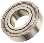 This is because this type of bearing is usually packed with dense grease which completely destroys its free motion, making it worse as a bearing than a simple hole-and-shaft arrangement. However, in spite of this, the closed or "sealed" bearing is popular as the magnets tend to attract dirt and dust and if the device is not enclosed in a steel box as is necessary for the high power versions, then having the seal is considered to be an advantage. The way to deal with the grease packing is to soak the bearing in an isopropyal solvent cleaner to remove the manufacturer's grease, and then, when it has dried out, lubricate the bearing with two drops of a high quality thin oil. If it is intended to house the motor/generator in an earthed, sealed steel box then an alternative type of bearing which might be suitable is an open design like this: 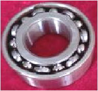 especially if the air is removed from the box. Some constructors perfer to use ceramic bearings which are supposed to be immune to dirt. One supplier is here but as with everything else, these choices have to be made by the builder and will be influenced by his opinions. I'm not sure where it came from, but here is a circuit diagram showing a transistor drive and the return of the back EMF of the drive coils to the driving power supply. Using this method, about 95% of the drive current can be returned, lowering the current draw enormously:  The diode feeding the power back to the supply is a Schottky type because of it's high-speed operation. It needs to be able to handle the peak pulse power and so should be one of the more robust types. What this circuit does not have is the very important switching on the output coils circuit. Another strange item is the way that the FET sensor is arranged with two sensors rather than one and with an additional battery. While it must be admitted that the current draw of the FET gate should be very low, there still does not seem to be much reason to have a second power supply. One other peculiarity in this diagram is the positioning of the drive coils. With them offset as shown, it has the effect of them being at an angle relative to the rotor magnets. It is not at all clear if this is an advanced operating technique or just poor drawing - I am inclined to assume the latter although I have no evidence for this other than the circuit design and the low quality of the original drawing which had to be improved considerably to arrive at the diagram shown above. The coil generator output should be fed into a capacitor before being passed to whatever equipment is to be powered by the device. This is because the energy is being drawn from the local environment and is not conventional energy. Storing it in a capacitor converts it to a more normal version of electrical power, a feature which has also been mentioned by Don Smith and by John Bedini although their devices are quite different in operation. The DC resistance of the coil windings is an important factor. The overall resistance should be either 36 ohms or 72 ohms for a complete set of coils, whether they are drive coils or power pick-up coils. Coils can be wired in parallel or in series or in series/parallel. So, for 72 ohms with four coils, the DC resistance of each coil could be 18 ohms for series-connected, 288 ohms for parallel connected, or 72 ohms for connection in series/parallel where two pairs of coils in series are then wired in parallel. To help with assessing the wire diameter and length which you could use, here is a table of some of the common sizes in both American Wire Gage and Standard Wire Gauge:  So far, we have not discussed the generation of the timing pulses. A popular choice for a timing system is to use a slotted disc mounted on the rotor axle and sensing the slots with an "optical" switch. The "optical" part of the switch is usually performed by UV transmission and reception and as ultra violet is not visible to the human eye, describing the switching mechanism as "optical" is not really correct. The actual sensing mechanism is very simple as commercial devices are readily available for performing the task. The sensor housing contains both a UV LED to create the transmission beam, and a UV dependent resistor to detect that transmitted beam. Here is an example of a neatly constructed timing mechanism made by Ron Pugh for his six-magnet rotor assembly: 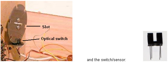 This device happens to be one which is supplied here under their product code number : OP-5490-14327-00. As the slotted disc rotates, one of the slots comes opposite the sensor and allows the UV beam to pass through to the sensor. That lowers the resistance of the sensor device and that change is then used to trigger the drive pulse for whatever length of time the slot leaves the sensor clear. You will notice the balanced attachment method used by Ron to avoid having an unbalanced rotor assembly. There can be two timing discs, one for the drive pulses and one for switching the power pickup coils in and out of the circuit. The slots in the power pick-up timing disk will be very narrow as the switch-on period is only about 2.7 degrees. For a six-inch diameter disc where 360 degrees represents a circumference length of 18.85 inches (478.78 mm) a 2.7 degree slot would be only 9/64 inch (3.6 mm) wide. The arrangement for an axial magnet rotor set-up could be like this:  So to recap, the things which are necessary for getting an Adams Motor output into the serious bracket are:
If you want the original drawings and some explanation on the operation of the motor, then two publications from the late Robert Adams can be bought from www.nexusmagazine.com where the prices are quoted in Australian dollars, making the books look much more expensive than they actually are. Here is a really impressive collection of well-informed practical material on building and using an Adams motor with details of sensors and how they work, core materials and their performances and how to locate the "sweet spot" - very highly recommended web site.  Tewari Paramahamsa’s Self-Powered Generator In April 2015, the famous 80-year old Indian scientist Tewari (www.tewari.org) well-known for his use of the homopolar generator to produce large volumes of hydrogen for commercial use, announced his successful 20-kilowatt, self-powered generator design and his corresponding patent application, shown below, was published. Here is a picture of a prototype, which is held together by four spring-loaded straps. The coils are held in place inside the frame and permanent magnets are spun inside those frames: 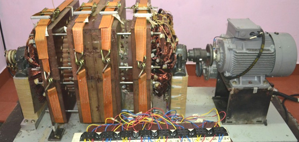 The principle of operation is simple and elegant. The power output conductors are arranged in such a way so that half of the magnetic field generated by the output current (that is, the magnetic field which opposes the motor spinning the rotor) is in one direction and the remaining half is in the opposite direction, cancelling the effect of the first half. The result is an arrangement where increasing power output has no noticeable effect on the input power. In other words, the Lenz Law drag effect has been effectively overcome. Tewari is due our warmest congratulations for what he has achieved. Being sensible, Tewari does not mention anything about 20 kilowatts of self-powered output, but instead, puts the design forward as being an improvement in the design of existing generators – and it is most certainly that. Here is his patent application: Abstract: A reduced reaction alternating current generator including a hollow stator core, a cylindrical rotor within the stator, a freely rotating shaft coupled to the rotor, a first set of magnets in which the south pole of each magnet is coupled to the surface of the rotor and the north pole of each magnet is facing the inner surface of the hollow stator core, a second set of magnets in which the north pole of each magnet is coupled to the surface of the rotor and the south pole of each magnet is facing the inner surface of the hollow stator core, and a set of silicon steel pieces coupled to the outer surface of the rotor comprised of individual silicon steel pieces positioned adjacent to and longitudinally in line with each individual magnet within the first set of magnets and each individual magnet within the second set of magnets. Description: BACKGROUND OF THE INVENTION Michael Faraday discovered the principles of electromagnetic induction and invented the rotating electrical generator in 1832. The generator was known as the Unipolar Generator, Acyclic Generator and Disk Generator. This generator operated on the principle that voltage is induced in a conductor in relative motion to an external magnetic field. Moreover, when the conductor is configured as a closed circuit and is in relative motion with an external magnetic field, a current will be induced to flow through that circuit. The induced current itself will generate an induced magnetic field surrounding the conductor. The direction of the induced current is determined by Fleming's right hand rule which states that the magnetic field produced by the current induced in the conductor will repel the external magnetic field which induced the current in the conductor. As such, the induced magnetic field surrounding the conductor and the external magnetic field repel each other so as to create a torque on the conductor which opposes that conductor's movement relative to the external magnetic field. Faraday's generator and all subsequent generators have in common, the production of this counter or back-torque. The efficiency of an electrical generator is governed by mechanical and electrical limitations. The mechanical limitations include windage and friction of the generator's rotor and bearings. The electrical limitations include electrical impedance within the windings of the generator as well as the above-described counter or back-torque. A prime mover is attached to a generator so as to cause the rotation of the generator's rotor resulting in the production of either a direct or an alternating current within the generator's conductor and a back-torque which counters the rotation caused by the prime mover. The prime mover may be powered by steam, wind or water. Therefore, the problem with standard generators is that their efficiency is limited due to back-torque generated as a result of current induced within the generator's conductor windings. DEFINITIONS The following definitions are provided for convenience and are not to be taken as a limitation of the present invention. Fleming's Left Hand Rule refers to the effect that when a current flows in a conductor and an external magnetic field is applied across that current flow, the conductor will experience a force perpendicular to both the external magnetic field and the direction of the current flow. The Left Hand Rule can be used to represent three mutually orthogonal axes using the thumb to represent a mechanical force, the first finger to represent a magnetic field and the middle finger to represent the current, each finger positioned at right angles to each other. Synchronous generator refers to an electrical generator which turns at the same speed as the drive mechanism, also known as the synchronous speed. A synchronous generator produces an alternating current and voltage at a frequency proportional to the rotation speed and to the number of excitation poles internal to the generator. Asynchronous generator refers to an alternating current generator that uses the principles of induction to produce power. Asynchronous generators operate by mechanically turning their rotor faster than the synchronous speed, giving negative slip. Low carbon steel refers to steel containing less carbon than other steels. This steel is inherently easier to cold-form due to its soft and ductile nature. Grain-oriented electrical steel refers to sheet steel used for laminations in power transformers having a silicon level of 3% or less. SUMMARY OF THE INVENTION It is the primary purpose of the present invention to overcome the above problems by providing a reduced reaction rotating alternating current generator providing improvement in efficiency characteristics not currently available in standard alternating current generators. To accomplish this objective, according to one embodiment of the present invention a reduced reaction alternating current generator is disclosed comprising a hollow stator core having an axis comprised of longitudinally positioned sheets laminated with a high permeability magnetic material, the laminated sheets including longitudinally embedded slots in which a conductor winding is laid parallel to the axis, a cylindrical rotor concentric with and positioned inside the hollow stator core comprised of a high permeability magnetic material and a shaft coupled to the rotor and driven by an external source so as to freely rotate the rotor relative to the hollow stator core. The generator comprises a first set of magnets in which the south pole of each magnet is coupled to the surface of the rotor and the north pole of each magnet is facing the inner surface of the hollow stator core, a second set of magnets in which the north pole of each magnet is coupled to the surface of the rotor and the south pole of each magnet is facing the inner surface of the hollow stator core and a set of silicon steel pieces coupled to the outer surface of the rotor comprised of individual silicon steel pieces positioned adjacent to and longitudinally in line with each individual magnet within the first set of magnets and each individual magnet within the second set of magnets. In addition to the foregoing, other features, objects and advantages of the present invention will become apparent from the following description. BRIEF DESCRIPTION OF THE DRAWINGS The following detailed description, which is given by way of example only, will best be appreciated in conjunction with the accompanying drawings in which: Fig.1 depicts a longitudinal cross-sectional view of a reduced reaction alternating current generator according to an example embodiment of the present invention; Fig.2 depicts an end cross-sectional view of a reduced reaction alternating current generator according to an example embodiment of the present invention; Fig.3 depicts a centre cross-sectional view of a reduced reaction alternating current generator according to an example embodiment of the present invention; Fig.4 depicts a longitudinal cross-sectional view of the flow of magnetic fields emanating from the first set of magnets within a reduced reaction generator according to an example embodiment of the present invention; Fig.5 and Fig.6 depict the interaction between the magnetic flux originating from the north poles of the first set of magnets and the magnetic flux resulting from an induced current in the conductor winding according to an example embodiment of the present invention; Fig.7 depicts a longitudinal cross-sectional view of the flow of magnetic fields emanating from the second set of magnets within a reduced reaction generator accordance to an example embodiment of the present invention; and Fig.8 and Fig.9 depict the interaction between the magnetic flux originating from the south poles of the second set of magnets and the magnetic flux resulting from an induced current in the conductor winding according to an example embodiment of the present invention. DETAILED DESCRIPTION OF THE INVENTION The present invention relates to a reduced reaction rotating alternating current generator providing improvement in efficiency characteristics not currently available in standard alternating current generators.  Fig.1 depicts a longitudinal cross-sectional view of a reduced reaction alternating current generator according to an example embodiment of the present invention. As shown in Fig.1, the induction machine 100 comprises a shaft 101, a rotor 102, a stator 103, a first set of magnets 104, a second set of magnets 105 (not shown), a conductor winding 106 and silicon steel pieces 107. The rotor 102 is a cylinder of high permeability magnetic material attached directly to the shaft 101 using any conventional known method that provides for a secure and permanent bonding under normal operating conditions. The rotor 102 is dimensioned so as to be fully enclosed within the stator 103 while the shaft 101 extends beyond one or both ends of the stator 103. The shaft 101 is mounted within the stator 103 so as to allow the shaft 101 and the attached rotor 102 to rotate freely within the stator 103 when the shaft 101 is driven by an external drive source. The external drive source is coupled to one end of the shaft 101 that extends beyond the stator 103. The external drive source may be driven either at a variable speed or at a synchronous speed. As such the drive source may be an alternating current (AC) based source or a direct current (DC) based source. The drive source may also be a non-electric based drive source such as a hydro, wind or an internal combustion based source. The means of coupling the drive source to the shaft 101 will be dependent on the type of drive source and any conventionally known means appropriate to that drive source type. In an example embodiment, the shaft is 30 mm diameter 1018 steel, the rotor is 370 mm diameter 1018 steel and the stator has a 570 mm diameter. Provisions are made on the cylindrical surface of the rotor 102 for the mounting of the first set of magnets 104 and for the mounting of the second set of magnets 105 near each of the ends of the rotor 102. Provisions are also made for the mounting of the silicon steel pieces 107 on the rotor at positions near the centre of the rotor. The first set of magnets 104 and the second set of magnets 105 (not shown) are attached to the ends of the rotor cylinder 102 using any conventional method known to provide a secure and permanent bonding under normal operating conditions. Each end of the rotor 102 contains one of the first set of magnets 104 and one of the second set of magnets 105, for a total of four magnets. The first set of magnets 104 are oriented with their north poles facing the stator 103 and their south poles coupled to the rotor 102. The second set of magnets 105 (not shown) are oriented with their south poles facing the stator 103 and their north poles coupled to the rotor 102. The magnets may be permanent magnets or electromagnets. In an example embodiment, the permanent magnets are Neodymium magnets with a maximum energy product (BHmax) of 48 to 50 MGOe. Moreover, in another example embodiment, the electromagnets are radial pole and are attached to the rotor in a manner generally known in the industry. The silicon steel pieces 107 are also attached to the rotor 102 using any conventional method known to provide a secure and permanent bonding under normal operating conditions. There is a single silicon steel piece 107 corresponding to each magnet of the first and second sets of magnets 104 attached to the rotor 102. Each silicon steel piece 107 is positioned in line with its corresponding magnet leaving a predefined distance 109 between silicon steel piece and its corresponding magnet. Each silicon steel piece 107 is comprised of silicon steel which is a speciality steel tailored to have a small magnetic hysteresis area and high magnetic permeability. A high magnetic permeability is defined as having a magnetic saturation level above 1.8 Teslas. In an example embodiment, the first and second sets of magnets 104, 105 and the silicon steel pieces 107 are each dimensioned to have approximately the same surface area and the distance 109 between silicon steel piece and a corresponding magnet is no more than the length of the magnet in the axial plane. The rotor 102 and the attached magnets 104, 105 and steel pieces 107 are each sized as to provide for an air-gap 108 of a predetermined size between the outer surfaces of the attached magnets 104, 105 and silicon steel pieces 107 and the inner surface of the stator 103. The air gap is chosen to provide free rotation of the rotor 102 and the attached first and second sets of magnets 104, 105 within the stator 103 as well as the efficient flow of magnetic flux into and out of the stator 103 across the air-gap 108. In an example embodiment, the air-gap 108 is within a range of 3 mm to 10 mm. The stator 103 is composed of longitudinally placed silicon steel laminates having grains oriented along the path of the magnetic flux that enters and exits the stator 103. The stator 103 also includes longitudinally oriented slots in which the conductor winding 106 is laid, the conductor winding 106 positioned such as to be cut through by the rotating magnetic flux originating from the first and second sets of magnets 104 attached to the rotating motor 102. In an example embodiment, the stator is comprised of a magnetically inert material, such as PVC piping, of suitable strength to support grain oriented steel lamination sheets. In an example embodiment, the magnetic flux emanating from the first and second magnets is approximately 10,000 Gauss.  Fig.2 depicts an end cross sectional view of a reduced reaction alternating current generator according to an example embodiment of the present invention. As shown in Fig.2 the first set of magnets 104 with their north poles facing the stator 103 and their south poles coupled to the rotor 102 are positioned at opposing in-line positions on one end of the rotor 102. Similarly, the second set of magnets 105 with their south poles facing the stator 103 and their north poles coupled to the rotor 102 are positioned at opposing in-line positions on the same end of the rotor 102 at a ninety degree offset from the first set of magnets 104. An identical first set of magnets 104 and second set of magnets 105 are coupled to the other end of the rotor 102 at similar positions  Fig.3 depicts a centre cross sectional view of a reduced reaction alternating current generator according to an example embodiment of the present invention. As shown in Fig.3, a single silicon steel piece 107 is positioned longitudinally in line with each magnet of the first and second sets of magnets 104, 105 (not shown). The position of each silicon steel piece 107 provides for a predefined distance 108 between a silicon steel piece 107 and its corresponding magnet. In an example embodiment, the distance between a silicon steel piece 107 and its corresponding magnet is equal to the longitudinal length of the magnet. Referring again to Fig.1, an electromagnetic force (EMF) is created across the conductor winding 106 embedded within the stator 103 when the magnetic flux emanating from the first set of magnets 104 and from the second set of magnets 105 cut through the conductor winding 106 as the rotor 102 rotates. Looking in the direction of arrow C in Fig.1, with the rotor 102 turning in a clockwise direction and the magnetic flux emanating in a vertically upward direction from the north poles of the first set of magnets 104, the current generated as a result of the induced electromagnetic force will travel from left to right 110 within the conductor winding 106. The current direction is as per Lenz's Law which states when an electric current is induced in a conductor, the direction of the induced current is such that its magnetic effect will oppose the action that gives rise to the induced current. As such, the direction of the induced current 110 results in a torque such as to oppose the clockwise rotation of the rotor 102. Specifically, looking in the direction of the arrow C in Fig.1, the interaction between the counter-clockwise magnetic field surrounding the conductor as a result of the induced electromagnetic force and the upward magnetic flux emanating from the north poles first pair of magnets 104 will create a counter-clockwise torque opposing the clockwise rotation of the rotor 102.  Fig.4 depicts a longitudinal cross sectional view of the flow of magnetic fields emanating from the first set of magnets within a reduced reaction generator. As shown in Fig.4, the magnetic flux 401 emanating from the north poles of the first set of magnets 104 travels vertically upwards, across the air gap 108 and into the stator 103 as the magnetic flux 401 rotates with the rotor 102 relative to the stator 103. As this rotating magnetic flux 401 enters the static stator 103, it cuts sideways across the conductor winding 106 embedded within the stator 103 and induces a current within the conductor winding 106. Within the stator 103, a portion of magnetic flux 402 is now trapped within the grain stampings within the stator 103 and flows longitudinally in an effort to return to a corresponding south pole of the first set of magnets 104. This portion of the magnetic flux 402 is now static relative to the stator 103 and the embedded conductor winding 106. As such, this portion of the magnetic flux 402 flows through and exits the stator 103 without any sideways movement relative to the embedded conductor winding 106 and therefore without inducing a current within the conductor winding 106. Outside the stator 103, a portion of the magnetic flux 403 crosses the air gap 108 and reaches the surface of a corresponding steel piece 107. The steel piece 107 focuses the magnetic flux 403 within the air gap 108 providing a more efficient and specifically designed path for the magnetic flux 403 to return to a corresponding first set of magnets 104. The magnetic flux 403 passes through the steel piece 107 and returns to a corresponding south pole of the first set of magnets 104 thereby closing the magnetic flux loop between north and south poles of each magnet of the first set of magnets 104.  Fig.5 and Fig.6 depict the interaction between the magnetic flux originating from the north poles of the first set of magnets and the magnetic flux resulting from an induced current in the conductor winding. In both Fig.5 and Fig.6, the current 110 induced in the conductor winding 106 by the clockwise rotation of the rotor 102 is shown coming out of the page. Moreover, in accordance with the application of the right hand rule, the magnetic flux 501 surrounding the conductor winding 106 as a result of the induced current 110 is shown as having a counter-clockwise rotation. In Fig.5, the magnetic flux originating from the first set of magnets is shown traversing the air gap upwards and interacting with the magnetic flux surrounding the conductor winding. As shown in Fig.5, the magnetic field 401 originating from the first set of magnets 104 is strengthened on the right side of the conductor winding 106 due to the superimposition of the magnetic field 501 induced in the conductor winding 106 in the same direction. However, the magnetic field 401 originating from the first set of magnets 104, is weakened on the left side of the conductor winding 106 due to the superimposition of the magnetic field 501 induced in the conductor winding 106 in the opposite direction. As a result of this interaction, the net magnetic field in the air-gap 108 over the surfaces of the first set of magnets 104 results in the application of a counter-clockwise torque 502 to the rotor 102 which opposes the clockwise rotation of the rotor 102. This is in accordance with Lenz's Law and is confirmed by the right hand rule which shows that a conductor within an upward directed magnetic field and carrying a current in the induced direction (coming out of the page) will experience a counter-clockwise force.  In Fig.6, the portion of the magnetic flux which is routed back from the stator, downwards across the air gap and through a silicon steel piece is shown interacting with the induced magnetic flux surrounding the conductor winding. As shown in Fig.6, the magnetic field 403 routed down through the silicon steel piece 107 is strengthened on the left side of the conductor winding 106 due to the superimposition of the magnetic field 501 induced in the conductor winding 106 in the same direction. However, the magnetic field 403 is weakened on the right side of the conductor winding 106 due to the superimposition of the magnetic field 501 induced in the conductor winding 106 in the opposite direction. As a result, on the surface of the silicon steel piece 107, the magnetic field 403 develops a gradient from left to right thus creating a clockwise torque 602 which supports the clockwise rotation of the rotor 102. This is in accordance with Lenz's Law and is confirmed by the right hand rule which shows that a conductor winding 106 within a downward directed magnetic field 403 and carrying a current 110 in the induced direction (coming out of the page) will experience a clockwise force. Therefore, as a result of this configuration, the conductor winding 106 embedded within the stator 103 is cut at two places by each magnetic flux originating from the north pole of the first set of magnets 104. Specifically, a first time when the magnetic field 401 enters the stator 103 in an upward direction and a second time when the magnetic field 403 exits the stator 103 in a downward direction through a silicon steel piece 107. The net effect is that the clockwise torque generated by the magnetic field 403 rerouted through the silicon steel pieces 107 partially cancels the counter-clockwise torque generated by the magnetic field 401 originating from the north poles of the first set of magnets 104. This results in a partial nullification of the back torque reaction caused by the effect of Lenz's Law reaction and results in a corresponding increase in the efficiency of the machine because the external drive source has to supply less torque to overcome the reduced reaction of the machine.  Fig.7 depicts a longitudinal cross-sectional view of the flow of magnetic fields emanating from the second set of magnets within a reduced reaction generator. As shown in Fig.7, the magnetic flux 701 flowing into the south pole of the second set of the magnets 105 travels vertically downwards from within the stator 103 and across the air gap 108 as the magnetic flux 701 rotates with the rotor 102 relative to the stator 103. As this rotating magnetic flux 701 exits the static stator 103, it cuts sideways across the conductor winding 106 embedded within the stator 103 and induces a current within that conductor winding 106. Within the stator 103, a portion of the magnetic flux 702 flows longitudinally along the grain stampings within the stator 103 from a position where the magnetic flux 702 enters the stator 103. This portion of the magnetic flux 702 is static relative to the stator 103 and to the conductor winding 106 embedded within the stator 103. As such, this portion of the magnetic flux 702 enters and flows through the stator 103 without any sideways movement relative to the embedded conductor winding 106 and, therefore, without inducing a current within the conductor winding 106. Outside the stator 103, a portion of the magnetic flux 703 flows from a north pole of the second set of magnets 105, through a corresponding silicon steel piece 107, upwards across the air gap 108 and into the stator 103. The silicon steel piece 107 focuses the magnetic flux 703 within the air gap 108 providing a more efficient and specifically designed path for the magnetic flux 703 originating from a corresponding second set of magnets 105. The magnetic flux 703 exists the steel piece 107 and enters the stator 103 thereby closing the magnetic flux loop between the south and north poles of each magnet of the second set of magnets 105. Fig.8 and Fig.9 depict the interaction between the magnetic flux originating from the south poles of the second set of magnets and the magnetic flux resulting from an induced current in the conductor winding. In both Fig.8 and Fig.9, the current 110 induced in the conductor winding 106 by the clockwise rotation of the rotor 102 is shown as going into the page. Moreover, in accordance with the application of the right hand rule, the magnetic flux 801 surrounding the conductor winding 106 as a result of the induced current 110 is shown as having a clockwise rotation.  In Fig.8, the magnetic flux originating from the second set of magnets is shown traversing the air gap downwards and interacting with the magnetic flux surrounding the conductor winding. As shown in Fig.8, the magnetic field 701 originating from the second set of magnets 105 is strengthened on the right side of the conductor winding 106 due to the superimposition of the magnetic field 801 induced in the conductor winding 106 in the same direction. However, the magnetic field 701 originating from the second set of magnets 105 is weakened on the left side of the conductor winding 106 due to the superimposition of the magnetic fields 801 induced in the conductor winding 106 in the opposite direction. As a result of this interaction, the net magnetic field in the air-gap over the surfaces of the second set of magnets 105 results in the application of a counter-clockwise torque 802 to the rotor 102 which opposes the clockwise rotation of the rotor 102. This is in accordance with Lenz's Law and is confirmed by the right hand rule which shows that a conductor within a downwards directed magnetic field and carrying a current in the induced direction (going into the page) will experience a counter-clockwise force.  In Fig.9, the portion of the magnetic flux originally routed through the steel pieces 107, across the air gap 108 and into the stator is shown interacting with the induced magnetic flux surrounding the conductor winding. As shown in Fig.9, the magnetic field 703 routed upwards through a steel piece 107 and across the air gap 108 is strengthened on the left side of the conductor winding 106 due to the superimposition of the magnetic field 801 induced in the conductor winding 106 in the same direction. However, the magnetic field 703 is weakened on the right side of the conductor winding 106 due to the superimposition of the magnetic field 801 induced in the conductor winding 106 in the opposite direction. As a result, on the surface of the silicon steel piece 107, the magnetic field 703 develops a gradient from left to right thus creating a clockwise torque 902 which supports the clockwise rotation of the rotor 102. This is in accordance with Lenz's law and is confirmed by the right hand rule which shows that a conductor winding 106 within an upwards directed magnetic field 703 and carrying a current 110 in the induced direction (going into the page) will experience a clockwise force. Therefore, as a result of this configuration and as described above for the first set of magnets, the conductor embedded within the stator is cut at two places by each magnetic field terminating at the south pole of the second set of magnets. Specifically, a first time when the magnetic field 701 exits the stator 103 in a downward direction and a second time when the magnetic field 703 enters the stator 103 in an upward direction through a silicon steel piece 107. The net effect is that the clockwise torque generated by the magnetic field 703 rerouted through the silicon steel pieces 107 partially cancels the counter-clockwise torque generated by the magnetic field 701 terminating at the south pole of the second set of magnets 105. This results in a partial nullification of the back torque reaction caused by the effect of Lenz's Law reaction and results in a corresponding increase in the efficiency of the machine because the external drive source has to supply less torque to overcome the reduced reaction of the machine. Lidmotor’s Low-voltage Rotor One very experienced developer whose YouTube ID is “Lidmotor” (because he makes motors from the lids of jars) has a short video here showing a very simple rotor design with one of his jar lids mounted on a single bearing: 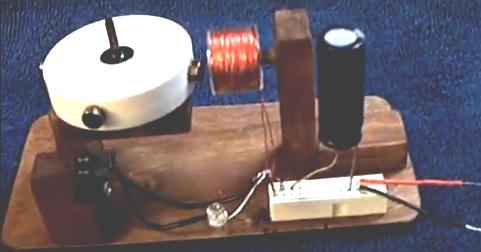 The white lid has four magnets attached to it spaced out evenly around the lid at ninety-degree intervals. Facing them is an air-core coil mounted on a non-magnetic support dowel and wound with 400 turns of ’30-gauge’ wire on a plastic spool. As ‘Lidmotor’ is American, the ’30 gauge’ wire is likely to be American Wire Gauge #30 with a diameter of 0.255 mm as opposed to the European Standard Wire Gauge size which has a 0.315 mm diameter. An air-core coil has no effect on the passing rotor magnets IF it is not carrying current. An output coil will cause drag on the rotor if current is being drawn from the coil, and so timed output switching as used by Robert Adams would be needed to not just overcome the drag, but to push the rotor on its way as well. There are two very important features of this rotor drive design. One is the fact that a supercap (10-Farad, 2.3V) is used to drive the rotor and when supplied with a charge of only 0.5V to 1.0V, can spin the rotor for up to thirty minutes. That very long time is likely to be a feature of the second important item which is that he has placed an LED across the reed switch used to power the coil. When the reed switch opens, a back-EMF voltage spike occurs and the LED feeds that voltage pulse back into the 100% efficient supercap, recovering most of the current used to drive the rotor. This is the same method as used by Robert Adams in his motor designs. Lidmotor presents his circuit like this: 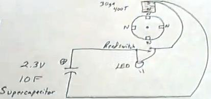 While the circuit shows the magnet operating the reed switch as being 180 degrees around from the coil, the photograph indicates that the switching magnet is one 90 degrees away. Any of the other magnets can be used. The reed switch operation is adjusted to get the best performance. This is done by moving the switch backwards and forwards along the moving path of the magnet to make the switching occur earlier or later. The objective is to push the rotor magnet on its way by pulsing the coil very briefly just after the rotor magnet has passed the centre of the coil. The length of time that the reed switch is closed can be adjusted by moving the switch closer to the magnet for a longer switch-closed time, or further away for a shorter switch closure. It is also possible to alter the closed time by positioning the switch across the path of the magnet travel or parallel to it. If you are not familiar with a reed switch, it is just a glass tube, filled with an inert gas, and with two overlapping metal strips inside the tube:  The external magnetic field magnetises the strips and they spring together due to magnetic attraction and spring apart again when the magnetic field moves away. These switches come in various sizes and the smallest version tends to be unreliable and has a very low maximum current capacity. The larger versions are much more robust. Lidmotor’s circuit is very simple and very effective, even though the rotor will have minimal weight and no significant drag. One wonders if adding a second coil and a diode feeding the supercapacitor, if the system could not become self-running. Teruo Kawai’s COP=3.18 Magnetic Motor. In July 1995, a patent was granted to Teruo Kawai of Japan, for an electric motor. In the patent, Teruo states that a measured electrical input of 19.55 watts produced an output of 62.16 watts, and that is a COP of 3.18. The main sections of that patent are included in the Appendix. This is an interesting design which has twelve stator electromagnets surrounding a rotor which has three magnetic poles:  The left hand diagram shows the front face of the motor with its twelve red electromagnets surrounding an unusually shaped steel rotor (coloured yellow). The right hand diagram shows a cross-section through the motor. The blue rectangles are permanent magnets which Teruo describes as being “a ring of permanent magnets” although it is not immediately obvious why a ring magnet should not be used – perhaps none with the necessary diameters were available. He also says that the magnets are bolted to the rotors. The frame material supporting the ball bearings and electromagnets is any suitable non-magnetic material and while aluminium is mentioned, I would strongly recommend that neither aluminium nor copper is used, especially since plastic chopping board material is very cheap and highly robust. The rotor and stator are somewhat unusual:  Because of the inner magnets, each of the steel rotors have three poles each – three North poles at one end and three South poles at the other end. The axle of the motor is made of good quality stainless steel as that is both robust and non-magnetic. The switching of the supply current is similar to that of the Charles Flynn magnet motor, and Teruo’s motor has been measured with COP>3 which means that the output power is more than three times greater than the input power. The input power switching occurs four times per revolution and it occurs just as the leading edge of a rotor arm approaches an electromagnet (the electromagnets shown in blue are powered up):  Here, the electromagnets shown in blue have just been powered up and this draws the yellow rotor arms in a clockwise direction towards those powered up electromagnets. The magnetic force is in attraction mode and while this is slightly less powerful than repulsion mode, it does not have an adverse effect on the magnets which should remain in top condition for many years. The switching suggested is the same as for the Charles Flynn motor, and that is an optical timing disc mounted on the axle shaft:  While Teruo shows various alternative versions of the motor, he states the result of a test run on the motor: “Pure steel was used as a magnetic material. It was 30 mm thick with teeth of 218 mm diameter and notches of 158 mm diameter. A 1000 gauss ferrite magnet was used as the permanent magnet. Electric power of 19.55 watts was applied to the electromagnets (17 volts at 1.15 amps). This produced 100 rpm with a torque of 60.52 Kg-cm and an output of 62.16 watts”. While an optical switching disc certainly works well, it will produce a rotational speed which is determined by the power supply and the load. I suggest that a simple divide-by-four power supply would give speed control:  The Buie-Morin Power System   Thomas Buie of America and Gerard Morin of Canada both worked on developing a self-powered system which provides kilowatts of excess power to power other equipment. Thomas feels strongly that water and electricity are part of a person’s rights and not a privilege which has to be paid for. They developed this self-powered generator in order to supply the electric needs of a household. First, we need to know what sort of power is used by typical household appliances. Perhaps this illustration might help:  These power levels are only approximate as many devices have different power settings which the user can select. For example, in Iraq during the night, some households have communal air conditioning of only 1000 watts, Americans have daytime air conditioning of at least 3000 watts while in Britain almost no households have any kind of air conditioning, while some adults in India don’t know what an electric fire is. Anyway, it would be nice to be able to power electrical equipment without having to pay for electricity, and that is what this system allows you to do, whether it is the 120 volts 60 cycles per second used in America or the 240 volt 50 cycles per second used in the rest of the world. The self-powered electricity generator which can provide you with free electricity is essentially very simple in outline. A battery is used to power a standard DC-to-AC inverter. Then the voltage is stepped up to around 400 volts. Next, a special controller is used to feed that 400 volts to a powerful motor at high frequency, and finally, the motor is used to spin an AC generator called an “alternator” which produces the electricity which we want. Part of that electricity is fed back to the battery and inverter input in order to make the system self-powered:  The “magic” is caused by the high voltage and the high speed pulses with which that voltage is applied to a carefully chosen type of motor. With 700 watts of input power, the system puts out 10,000 watts of power. The most important components of this system are the controller and the motor. You are probably familiar with the most common type of motor which is a single-phase motor, but the more powerful motors used in industry are three-phase motors. There are several varieties of three-phase motors, but the one which we want to use has 36 coils connected as three sets of twelve windings in parallel:  This is a very powerful arrangement as sending one pulse of current to each of these three chains, only advances the motor by 30 degrees. There is a continuous ring of magnets immediately outside the coils. This motor is used in a Samsung washing machine. A three-phase motor sounds very technical, but it really isn’t. It is just a motor which has three sets of drive coils instead of just one coil:  So, the motor has effectively just three coils in it and it is made to go round by pulsing the coils in order, that is coil 1, then coil 2, then coil 3, then coil 1 again and so on. The more rapidly the coils are pulsed, the faster the motor rotates, and in this system that rotation can be very fast indeed. The pulsing of those three coils sets one after the other in sequence, is done by the “controller” unit which is a key component in this design. The motor is a permanent magnet, synchronous motor which has no sensors built into it. That sounds ever so impressive, but it is actually the cheapest type of three-phase motor, and because it has no sensors, it is the most difficult to drive reliably. There are several varieties of three-phase motors, but the one which we want to use has 36 coils connected as three sets of twelve coils in parallel. The controller consists of two parts. The first is an Arduino board which is a general purpose development board - essentially a simple computer which can be programmed from an ordinary PC or laptop. It holds the program in its memory and runs it whenever it is instructed to do so. The second part is an electronics link between the Arduino board and the motor. That link boosts the power fed to the motor using high-power transistors which can feed high currents to the motor, and some other wires which feed information back to the Arduino board to give it full control of what is happening with the motor. The Arduino program powers the motor coils in sequence and as well as that, it senses the position of the actual rotor as it spins. It does that by sensing the voltages in each of the three coil sets at all times. At the web site here The motor is offered at £150 and here also at £150.  It is not necessary for you to become an expert programmer of an Arduino board as the program used is provided for you here. A good instruction video on programming the Arduino Uno board is shown here. The Arduino code is shown below is from here but can be downloaded as a text file from: here. // Sensorless brushless DC (BLDC) motor control with Arduino UNO (Arduino DIY ESC). // This is a free software without any warranty. #define SPEED_UP A0 #define SPEED_DOWN A1 #define PWM_MAX_DUTY 255 #define PWM_MIN_DUTY 50 #define PWM_START_DUTY 100 byte bldc_step = 0, motor_speed; unsigned int i; void setup() { DDRD |= 0x38; // Configure pins 3, 4 and 5 as outputs PORTD = 0x00; DDRB |= 0x0E; // Configure pins 9, 10 and 11 as outputs PORTB = 0x31; // Timer1 module setting: set clock source to clkI/O / 1 (no prescaling) TCCR1A = 0; TCCR1B = 0x01; // Timer2 module setting: set clock source to clkI/O / 1 (no prescaling) TCCR2A = 0; TCCR2B = 0x01; // Analog comparator setting ACSR = 0x10; // Disable and clear (flag bit) analog comparator interrupt pinMode(SPEED_UP, INPUT_PULLUP); pinMode(SPEED_DOWN, INPUT_PULLUP); } // Analog comparator ISR ISR (ANALOG_COMP_vect) { // BEMF debounce for(i = 0; i < 10; i++) { if(bldc_step & 1){ if(!(ACSR & 0x20)) i -= 1; } else { if((ACSR & 0x20)) i -= 1; } } bldc_move(); bldc_step++; bldc_step %= 6; } void bldc_move(){ // BLDC motor commutation function switch(bldc_step){ case 0: AH_BL(); BEMF_C_RISING(); break; case 1: AH_CL(); BEMF_B_FALLING(); break; case 2: BH_CL(); BEMF_A_RISING(); break; case 3: BH_AL(); BEMF_C_FALLING(); break; case 4: CH_AL(); BEMF_B_RISING(); break; case 5: CH_BL(); BEMF_A_FALLING(); break; } } void loop() { SET_PWM_DUTY(PWM_START_DUTY); // Setup starting PWM with duty cycle = PWM_START_DUTY i = 5000; // Motor start while(i > 100) { delayMicroseconds(i); bldc_move(); bldc_step++; bldc_step %= 6; i = i - 20; } motor_speed = PWM_START_DUTY; ACSR |= 0x08; // Enable analog comparator interrupt while(1) { while(!(digitalRead(SPEED_UP)) && motor_speed < PWM_MAX_DUTY){ motor_speed++; SET_PWM_DUTY(motor_speed); delay(100); } while(!(digitalRead(SPEED_DOWN)) && motor_speed > PWM_MIN_DUTY){ motor_speed--; SET_PWM_DUTY(motor_speed); delay(100); } } } void BEMF_A_RISING(){ ADCSRB = (0 << ACME); // Select AIN1 as comparator negative input ACSR |= 0x03; // Set interrupt on rising edge } void BEMF_A_FALLING(){ ADCSRB = (0 << ACME); // Select AIN1 as comparator negative input ACSR &= ~0x01; // Set interrupt on falling edge } void BEMF_B_RISING(){ ADCSRA = (0 << ADEN); // Disable the ADC module ADCSRB = (1 << ACME); ADMUX = 2; // Select analog channel 2 as comparator negative input ACSR |= 0x03; } void BEMF_B_FALLING(){ ADCSRA = (0 << ADEN); // Disable the ADC module ADCSRB = (1 << ACME); ADMUX = 2; // Select analog channel 2 as comparator negative input ACSR &= ~0x01; } void BEMF_C_RISING(){ ADCSRA = (0 << ADEN); // Disable the ADC module ADCSRB = (1 << ACME); ADMUX = 3; // Select analog channel 3 as comparator negative input ACSR |= 0x03; } void BEMF_C_FALLING(){ ADCSRA = (0 << ADEN); // Disable the ADC module ADCSRB = (1 << ACME); ADMUX = 3; // Select analog channel 3 as comparator negative input ACSR &= ~0x01; } void AH_BL(){ PORTB = 0x04; PORTD &= ~0x18; PORTD |= 0x20; TCCR1A = 0; // Turn pin 11 (OC2A) PWM ON (pin 9 & pin 10 OFF) TCCR2A = 0x81; // } void AH_CL(){ PORTB = 0x02; PORTD &= ~0x18; PORTD |= 0x20; TCCR1A = 0; // Turn pin 11 (OC2A) PWM ON (pin 9 & pin 10 OFF) TCCR2A = 0x81; // } void BH_CL(){ PORTB = 0x02; PORTD &= ~0x28; PORTD |= 0x10; TCCR2A = 0; // Turn pin 10 (OC1B) PWM ON (pin 9 & pin 11 OFF) TCCR1A = 0x21; // } void BH_AL(){ PORTB = 0x08; PORTD &= ~0x28; PORTD |= 0x10; TCCR2A = 0; // Turn pin 10 (OC1B) PWM ON (pin 9 & pin 11 OFF) TCCR1A = 0x21; // } void CH_AL(){ PORTB = 0x08; PORTD &= ~0x30; PORTD |= 0x08; TCCR2A = 0; // Turn pin 9 (OC1A) PWM ON (pin 10 & pin 11 OFF) TCCR1A = 0x81; // } void CH_BL(){ PORTB = 0x04; PORTD &= ~0x30; PORTD |= 0x08; TCCR2A = 0; // Turn pin 9 (OC1A) PWM ON (pin 10 & pin 11 OFF) TCCR1A = 0x81; // } void SET_PWM_DUTY(byte duty){ if(duty < PWM_MIN_DUTY) duty = PWM_MIN_DUTY; if(duty > PWM_MAX_DUTY) duty = PWM_MAX_DUTY; OCR1A = duty; // Set pin 9 PWM duty cycle OCR1B = duty; // Set pin 10 PWM duty cycle OCR2A = duty; // Set pin 11 PWM duty cycle } The Arduino board looks like this:  The interface between the Arduino Uno board and the motor, needs the following components: • 6 x IRF840 FET transistors • 3 x IR2104 DIP gate driver IC • 3 x 1.3K ohm 0.55 watt resistors • 3 x 10K ohm 0.5 watt resistors • 3 x 33K ohm 0.25 watt resistors • 6 x 100 ohm quarter watt resistors • 3 x IN5508 diodes • 3 x 10uF 25 volt capacitors. • 3 x 2.2uF 25 volt capacitors. • 2 x pushbuttons • 12V source • Construction board and connecting wires These components are connected up like this: We need to connect this Arduino Uno up to drive one of the three phases of our three-phase motor, so to do that we will use an IR2104 driver chip and an IRF840 Field Effect Transistor (“FET”) to feed our 400 volt power supply to the motor at some 14,800 pulses per second. So, the power drive for the first phase is like this:  The 1N5408 diode can handle high voltages and so protect the 12 volt section of the circuit from the high voltage section feedback. The power drive for the second phase is:  And the Power drive for the third phase is:  But we also need to provide the Arduino board with feedback information to let it know where the motor is in it’s rotation. That is done by sensing the Phase connections to the motor like this:  First, a word of warning here. You can get a shock from any voltage above 30 volts. If the voltage is Alternating Current at a frequency under 100 cycles per second (as is supplied by your mains wall socket) then that shock can be serious. The power supply described here is very easy to understand and to make BUT if you get a shock from it that shock is very likely to kill you !! Disclaimer: You are responsible for your own actions. This document is for information purposes only and if you decide to make or experiment with voltages higher than 12 volts, then you and you alone are responsible for your actions and neither the author, the web hosting service nor anyone else is responsible for what you do or for any damage or injury caused by your own actions. Having said that, please understand that if you are careful and sensible, there is no danger in constructing this power generator in spite of the very high 400 volt input to this power driver circuit. To stay safe, you make all the necessary connections and insulate them before you apply power. So, we need to construct an electronics component board to connect the Arduino to the phases of the motor. Please remember that this board will be carrying 400 volts and so you need to enclose the board in a plastic box before powering it up. The suggestion for a physical layout for the components is based on using stripboard like this:  These boards come in many sizes and are very versatile. However, because the pin spacing of integrated circuit is just 0.1 inches, the solder joints can be very close together and that does not suit a beginner to soldering, so ask a friend for help in soldering unless you are already expert.  We want to place these components on the board, so perhaps a layout like this might be suitable:  The red circles show where the copper strip on the underside of the board is to be broken. You can make three separate board, one for each phase or you can place all three circuits on a single board. Integrated circuits are heat sensitive so I suggest that you use a socket and solder it in place and then plug the chip into the socket when everything is cool. An 8-pin socket looks like this:  Here is a possible physical layout for the Arduino / Motor interface using a piece of stripboard with 31 copper strips each with 39 holes in it:  Thomas Buie describes the power supply method which he has used successfully in the past. It is a very simple arrangement which uses readily available parts which can be purchased easily through the internet:  First, there is a car battery and that feeds an inverter like this particular unit which is an European inverter which produces anything from 220 to 240 volts with powers of 2000 watts continuous and 4000 watts peak output. It is also cheap at £25 delivered and it has two handy USB output power sockets as well:  However, we want 400 volts or more at 1 amp or more, and as that is some 800 watts for a 12 volt inverter like this, so Thomas has used a transformer to step the voltage up higher:  Getting a transformer like this is not at all easy as very few people want a 400 volt power supply. The rectification is very straightforward:  A possibility which bypasses the need for a transformer of that type would be to use a voltage doubler circuit to raise the inverter output up to 440 volts or so, the diodes being say, 1N5408 or UF5408 which can handle 1000 volts at 3 amps which is a good deal more than is needed for this system:  The disadvantage of doing that is that the output is effectively only a half-wave power supply. The capacitors would be 400 volts each and so the output capacitance would be safe for anything up to 800 volts. The transformer in the diagram is inside the inverter and “V” in the diagram would be 220 volts, giving an output of 440 volts. One possibility which avoids the need for a transformer and still provides a full wave rectified 440V output is to use two 220V inverters:  In this arrangement, both inverters are supplied by a single car battery and the output is 440 volts. Each inverter supplies only half of the wattage. It is suggested that a method which skips both the inverter and the transformer would be to use a “DC chopper” circuit which could take the 12 volts from the car battery and produce a 400 volt 20 kHz output directly in one operation. A DC chopper of that type looks like this:  While a DC chopper power supply is not suitable for all applications, it is felt that this cheap unit costing US $35 from https://s.click.aliexpress.com/e/1rHgPQC would be suitable for this generator project. While the circuit wiring is shown above, we need a physical board with the electronic components attached to it. The wiring connections are normally soldered joints but making those joints can be quite difficult as some of them are very close together. If you are experienced at soldering, then there should be no problem, but if you have not soldered before, then you should get an experienced friend to do the soldering for you. Here is a suggested board layout using stripboard often called “Veroboard”. No matter how the 400 volts is generated, it is necessary to feed some 70 amps back to the battery output and inverter input to sustain the motor indefinitely. While the diagram above just shows a battery charger, the level of feedback is much higher than any ordinary battery charger can supply. So, we are talking about a professional-level charger able to deliver some 700 watts of power continuously. This generator system has a Coefficient Of Performance greater than 14 but even with that high performance it needs an input of about 700 watts for an output of 10,000 watts. Consequently, this “battery charger” link is very important and commercial units which can do the job cost something like £150. We come now to the alternator which produces the electrical output which is the whole point of the system. All of the components and methods described so far have the objective of spinning the alternator indefinitely in order to provide electrical power for a household. However, please understand clearly that your local power company is most unlikely to allow you to connect your generator up to their wiring which goes to your fuse box. Consequently, it is better if you use your new supply of electrical power as if it were an emergency back-up generator. That is, you connect it up to your appliances without connecting it to any external power supply or wall socket. The system described so far is perfectly capable of driving an alternator of any power level up to ten kilowatts without altering any of the components. So, the size of the alternator which you buy is up to you. Personally, I would consider an output of five kilowatts as being adequate to excessive, but then my electrical needs are probably far lower than yours might be. Anyway, in the UK one supplier is MachineMart and they offer three different alternators. They look like this and each needs to be driven at 3000 rpm:   Looking at the small price difference between the alternators, there seems to be very little reason not to pick the 6.5 KVA unit even if your expected current is likely to be well below that rating. The KVA rating is the same as kilowatts IF the power factor of the load is 1, that is just light bulbs. Generally speaking, a 6.5 KVA alternator is considered to be a 5 kilowatt unit for driving washing machines, vacuum cleaners or the like. The final step is to mount the motor unit and alternator unit together so that the motor can drive the alternator to provide the required electrical output:  Thanks is due to Thomas Buie for sharing his design freely. Thomas has joined with the Free Energy Special Interest Group (“FESIG”) and they are preparing a series of instruction videos and actual physical construction of an a generator via the website here and you can ask questions during the live sessions. Thomas’ own website is here. The Arduino code file www.free-energy-info.com/Arduino.txt is a free download and this document is available free from www.free-energy-info.com. There is one issue which needs to be dealt with and that is the plastic construction of parts of the motor. The motor was intended to power a washing machine and because that operation is slow and the mechanical stresses involved are fairly low, plastic was used. In this application the stresses are much higher and the usage is all day every day as opposed to the occasional use of a washing machine (my apologies to mothers with children), it would be necessary to replace the plastic parts with mild steel, both for the hub of the rotor and the casing of the stator in order to drive the larger sizes of alternator. Machining by a local steel fabrication shop may be necessary unless you already own a lathe or have access to one. The existing plastic rotor boss:  is replaced with a metal unit:  and the motor effectively rebuilt until only the original coils and magnets remain:   While doing that adds considerable extra cost and effort, it does result in a very robust and powerful motor which is ready to drive a large alternator. The rotor is the metal casing with the magnets attached to it while the section containing the coils is stationary. Let me stress that if you were to construct a generator system like this, you do not connect it to the wiring of the local electricity power supply company. For example, the electrical mains supply wiring will come into your household fuse box or contact breaker box. Do not connect your generator wiring to that same box but instead treat your generator in the same way as an emergency generator, feeding the generator output directly to your washing machine, electric heater, vacuum cleaner or whatever through an extension cable and not through a wall socket. If you are very keen to have your new generator connected to your fuse box, then be sure to install a “Break-before Make” heavy duty switch to disconnect the outside power supply cable before your generator output is connected to the fuse box. This is important because if a fault occurs in the mains wiring and they turn off the mains power while they fix it, the workmen might get a fatal shock from your generator even though their wiring is supposed to be switched off. Update 17th March 2019 It has been pointed out that this possible version of the interface board which goes between the Arduino and the 400-volt drive to the 3-phase motor has one feature which could be considered to be a potential weakness. The three red arrows show a copper strip which passes from the 12-volt Arduino area into the 400-volt motor area and it is felt that there is the potential for a back-EMF voltage spike to be fed back along that copper track and damage the IR2104 chip or even the Arduino board itself. It is suggested that the introduction of a fast Schottky diode in those links would block that possibility. For that we would need a Schottky diode which can withstand the 400 to 500 volts which gets fed to the motor and the current needed by the motor. The Mouser supplier of electronic components has a range of such diodes. For example: SCS306AHGC9 rated at 650 volts, 6 amps and 46 watts, sells for £2.91 SCS308AHGC9 rated at 650 volts, 8 amps and 57 watts, sells for £3.47 SCS310AHGC9 rated at 650 volts, 10 amps and 71 watts, sells for £4.04 SCS312AHGC9 rated at 650 volts, 12 amps and 78 watts, sells for £4.76 SCS315AHGC9 rated at 650 volts, 15 amps and 93 watts, sells for £5.08 SCS320AHGC9 rated at 650 volts, 20 amps and 115 watts, sells for £6.17 The packaging is like this:  So, if we are to take the advice which recommends one of these diodes placed in line with lines which lead out to each phase of the motor, then the board layout would change to this:  However, please understand that the FESIG presentation deals with the construction of a multi-kilowatt generator in far greater detail than this and that includes the construction of a much more robust interface between the Arduino and the 3-phase motor. That interface does not use the IR2104 chip but instead constructs the interface using discrete components which are believed to be much more robust than the IR2104 chip. The FESIG presentation is to cover the operation and other relevant details of each component used in the construction and so the people being trained should understand clearly how every part of the generator works and so be able to perform maintenance if that should ever prove to be necessary. James Hardy’s Self-Powered Water-pump Generator. There is a video on Google which shows a self-powered electrical water-pump driven, electrical generator at this location. This is a very simple device where the jet of water from the pump is directed at a simple water-wheel which in turn, spins an electrical alternator, powering both the pump and an electric light bulb, demonstrating the capture and use of free-energy. 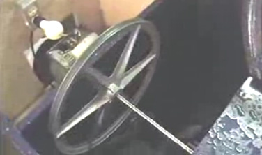 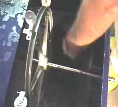 Initially, the generator is got up to speed, driven by the mains electrical supply. Then, when it is running normally, the mains connection is removed and the motor/generator sustains itself and is also able to power at least one light bulb. The generator output is normal mains current from a standard off-the-shelf alternator. James has Patent Application US 2007/0018461 A1 published in 2007 on his design. In that application he points out that a major advantage of his design is the low noise level produced when the generator is running. In the video and the pictures above, the demonstration has the housing opened up in order to show how the generator system works, but during normal use, the compartments are completely sealed. In his document, James shows the overall system like this:  The housing is divided into three separate compartments. The first compartment has a strong axle shaft running through it, supported on ball or roller bearings – possibly ceramic for this environment. The bearings are protected by being covered by splash guards which keep the water (or other liquid) off them. A waterwheel of almost any type is mounted on the shaft and a high-capacity water pump directs a stream of liquid on to the waterwheel, striking the paddles at right angles in order to provide the maximum impact. This first compartment is sealed in order to contain all of the liquid inside it and the bottom is effectively a sump for the liquid. A pipe located near the bottom of the compartment feeds the liquid to the pump which is located in the second compartment. The pump boosts the liquid through a nozzle, directing it at the waterwheel. While almost any nozzle will work, it is usual to choose one which produces a concentrated jet of liquid in order to generate the largest possible impact. One would expect that the larger the diameter of the waterwheel, the more powerful the system would be. However, that is not necessarily the case as other factors such as the overall weight of the rotating members might affect the performance. Experimentation should show the most effective combination for any given pump. The rotating shaft is given a third bearing supported by the side of the final compartment. The shaft then has a large diameter belt pulley mounted on it, the belt driving a much smaller pulley mounted on the shaft of the generator. This raises the rate at which the generator shaft is rotated. If the pump operates on AC mains voltage, then the generator will be one which generates mains voltage AC. If the pump operates on, say, 12 volts, then the generator will be one which generates 12 volts DC. The diagram above, shows the arrangement for a mains voltage system as that is probably the most convenient. If a 12-volt system is chosen, then the inverter can be omitted. The generator is started by pressing the ‘normally open’ press-button switch marked “A” in the diagram. This passes the battery power through to the 1-kilowatt inverter which then generates AC mains voltage. The switch marked “B” is a “changeover” switch, and for starting, it is set so that it passes the AC power through switch “A” to the pump. This causes the pump to turn on and direct a powerful jet of liquid at the waterwheel, forcing it around and so powering the generator. When the generator gets up to full speed, switch “B” is flipped over, disconnecting the inverter and feeding the generator power through to the pump, keeping it running and supplying additional power to the output power sockets mounted on top of the housing. The press-button switch is released, disconnecting the battery which is no longer needed. Switch “C” is an ordinary On/Off mains switch which is needed if you want to turn the generator off. A major advantage of this generator system is that the main components can be bought ready-made and so only very simple constructional skills and readily available materials are needed. Another advantage is that what is happening can be seen. If the pump is not working, then it is a simple task to discover why. If the generator is not spinning, then you can see that and sort the problem. Every component is simple and straightforward. James suggests that a suitable pump is the 10,000 gallons per hour “Torpedo Pump” from Cal Pump web site:  Georges Mourier’s COP=10,000 Motor/Generator Patent This patent from Frenchman Georges Mourier is quite remarkable in that it states clearly in the patent that it has a Coefficient Of Performance of 10,000 with an input power of just 10 watts producing an output of 100 kilowatts, which, considering the massive opposition of the US Patent Office to any claim of output power being greater than the input needed to produce that output, is little short of amazing. This patent contains a fair amount of mathematics where Georges goes about showing why there is a power amplification. This can be ignored by most people as the point to concentrate on is how to build a power-amplifying motor/generator. The RotoVerter. Not all pulsed-drive systems use permanent magnets as part of their drive mechanism. For example, the RotoVerter systems uses standard three-phase electric motors instead of magnets. In addition, some of the electrical driving power can be recovered for re-use. This system has been reproduced by several independent researchers and it produces a substantial power gain when driving devices which need an electrical motor to operate. The outline details are as follows:  The output device is an alternator which is driven by a three-phase mains-powered, 3 HP to 7.5 HP motor (both of these devices can be standard ‘asynchronous squirrel-cage’ motors). The drive motor is operated in a highly non-standard manner. It is a 240V motor with six windings as shown below. These windings are connected in series to make an arrangement which should require 480 volts to drive it, but instead, it is fed with 120 volts of single-phase AC. The input voltage for the motor, should always be a quarter of its rated operational voltage. A virtual third phase is created by using a capacitor which creates a 90-degree phase-shift between the applied voltage and the current.  The objective is to tune the motor windings to give resonant operation. A start-up capacitor is connected into the circuit using the press-button switch shown, to get the motor up to speed, at which point the switch is released, allowing the motor to run with a much smaller capacitor in place. Although the running capacitor is shown as a fixed value, in practice, that capacitor needs to be adjusted while the motor is running, to give resonant operation. For this, a bank of capacitors is usually constructed, each capacitor having its own ON/OFF switch, so that different combinations of switch closures give a wide range of different overall values of capacitance. With the six capacitors shown above, any value from 0.5 microfarad to 31.5 microfarad can be rapidly switched to find the correct resonant value. These values allow combined values of 0.5, 1.0, 1.5, 2.0, 2.5, 3.0, 3.5, .....by selecting the appropriate switches to be ON or OFF. Should you need a value greater than this, then wire a 32 microfarad capacitor in place and connect the substitution box across it to test higher values step by step to find the optimum value of capacitor to use. The capacitors need to be powerful, oil-filled units with a high voltage rating - in other words, large, heavy and expensive. The power being handled in one of these systems is large and setting one up is not without a certain degree of physical danger. These systems have been set to be self-powered but this is not recommended, presumably because of the possibility of runaway with the output power building up rapidly and boosting the input power until the motor burns out. The Yahoo EVGRAY Group at http://groups.yahoo.com/group/EVGRAY has a large number of members, many of whom are very willing to offer advice and assistance. A unique jargon has built up on this forum, where the motor is not called a motor but is referred to as a “Prime Mover” or “PM” for short, which can cause confusion as “PM” usually stands for “Permanent Magnet”. RotoVerter is abbreviated to “RV” while “DCPMRV” stands for “Direct Current Permanent Magnet RotoVerter” and “trafo” is a non-standard abbreviation for “transformer”. Some of the postings in this Group may be difficult to understand due to their highly technical nature and the extensive use of abbreviations, but help is always available there. To move to some more practical construction details for this system. The motor (and alternator) considered to be the best for this application is the “Baldor EM3770T” 7.5 horsepower unit. The specification number is 07H002X790, and it is a 230/460 volts 60Hz 3-phase, 19/9.5 amp, 1770 rpm, power factor 81, device. The Baldor web site is here and the following details should be considered carefully before trying any adaption of an expensive motor. The following constructional photographs are presented here by kind permission of Ashweth Palise of the EVGRAY Group. The end plate of the drive motor needs to be removed and the rotor lifted out. Considerable care is needed when doing this as the rotor is heavy and it must not be dragged across the stator windings as doing that would damage them.  The second end-plate is then removed and placed on the opposite end of the stator housing. 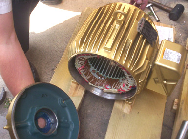 The fan is removed as it is not needed and just causes unnecessary drag, and the rotor is inserted the opposite way round to the way it was removed. That is, the housing is now the other way round relative to the rotor, since the rotor has been turned through 180 degrees before being replaced. The same part of the shaft of the rotor passes through the same end plate as before as the end plates have also been swapped over. The end plates are bolted in position and the rotor shaft spun to confirm that it still rotates as freely as before. To reduce friction to an absolute minimum, the motor bearings need to be cleaned to an exceptional level. There are various ways of doing this. One of the best is to use a carburettor cleaner spray from your local car accessories shop. Spray inside the bearings to wash out all of the packed grease. The spray evaporates if left for a few minutes. Repeat this until the shaft spins perfectly, then put one (and only one) drop of light oil on each bearing and do not use WD40 as it leaves a residue film. The result should be a shaft which spins absolutely perfectly. The next step is to connect the windings of the two units. The motor (the “Prime Mover”) is wired for 480 volt operation. This is done by connecting winding terminals 4 to 7, 5 to 8 and 6 to 9. The diagram shows 120 volts AC as being the power supply. This is because the RotoVerter design makes the motor operate at a much lower input than the motor designers intended. If this motor were operated in the standard way, a 480 volt 3-phase supply would be connected to terminals 1, 2 and 3 and there would be no capacitors in the circuit.  It is suggested that the jumpering of the motor windings is more neatly done by removing the junction box cover and drilling through it to carry the connections outside to external connectors, jumpered neatly to show clearly how the connections have been made for each unit, and to allow easy alterations should it be decided to change the jumpering for any reason. 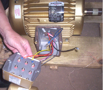
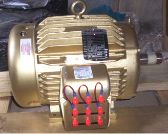 The same is done for the unit which is to be used as the alternator. To increase the allowable current draw, the unit windings are connected to give the lower voltage with the windings connected in parallel as shown below with terminals 4,5 and 6 strapped together, 1 connected to 7, 2 connected to 8 and 3 connected to 9. This gives a three-phase output on terminals 1, 2 and 3. This can be used as a 3-phase AC output or as three single-phase AC outputs, or as a DC output by wiring it as shown here:  The motor and the alternator are then mounted securely in exact alignment and coupled together. The switching of the direction of the housing on the drive motor allows all of the jumpering to be on the same side of the two units when they are coupled together, facing each other: 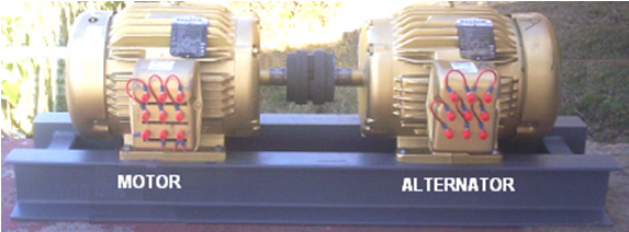 The input drive may be from an inverter driven from a battery charged via a solar panel. The system how needs to be ‘tuned’ and tested. This involves finding the best ‘starting’ capacitor which will be switched into the circuit for a few seconds at start-up, and the best ‘running’ capacitor. Help and advice is readily available from the EVGRAY Group as mentioned above. To summarise: This device takes a low-power 110 Volt AC input and produces a much higher-power electrical output which can be used for powering much greater loads than the input could power. The output power is much higher than the input power. This is free-energy under whatever name you like to apply to it. One advantage which should be stressed, is that very little in the way of construction is needed, and off-the-shelf motors are used. Also, no knowledge of electronics is needed, which makes this one of the easiest to construct free-energy devices available at the present time. One slight disadvantage is that the tuning of the “Prime Mover” motor depends on its loading and most loads have different levels of power requirement from time to time. A 220 Volt AC motor can also be used if that is the local supply voltage. If an alternator is being driven by the RotoVerter motor (the “Prime Mover”) but although the shaft is being rotated rapidly there is no output voltage, then it is likely that the alternator has been sitting around unused for a long time and has lost the magnetic properties which it needs at start-up. To fix this, connect each of the three output windings, one at a time, across a car battery for about five seconds to develop some magnetism and the alternator will then work. This is a one-off thing only needed after a long period of inactivity. It is not essential to construct the RotorVeter exactly as shown above, although that is the most common form of construction. The Muller Motor mentioned earlier, can have a 35 kilowatt output when precision-constructed as Bill Muller did. One option therefore, is to use one Baldor motor jumpered as the “Prime Mover” drive motor and have it drive one or more Muller Motor style rotors to generate the output power:  Coil-Shorting. The RotoVerter output and the Muller Motor/Generator output (and possibly, the Adams Motor output) can be increased very substantially by a technique developed by "Kone" the moderator of the EVGRAY Yahoo forum already mentioned. The technique is to place a dead short-circuit across each output coil, just as the magnetic field of that coil reaches a maximum. This is done five times in rapid succession and can boost the output power by an estimated factor of 100 times. On the surface, it appears complete madness to place a short-circuit across the very output which you are generating as the whole point of the exercise. However, it is not as mad as it seems. At the peak point, the coil itself contains a large amount of energy and when a short-circuit is placed across it, the result is quite unusual. The effect of short-circuiting an iron-cored coil has been demonstrated by Ron Pugh of Canada with a bench test using this equipment: 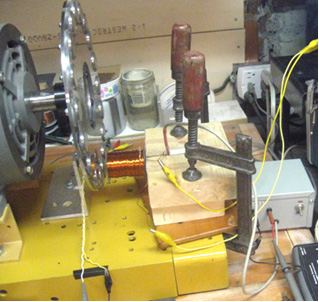 Here, a device for measuring magnetic fields is sensing the magnetic field of the coil as the rotor magnets move past the coil. The measurement is done with the coil operating normally and then again, with the coil short-circuited. The results are shown in these oscilloscope displays:  Quite surprisingly, the magnetic field is reversed by the short-circuit. If we consider just the first half of the cycle:  You will notice that when the open coil has a very strong positive position (relative to a North magnetic pole), the short-circuited coil has a strong reading of the opposite polarity. Therefore, at any given instance near the peak, there is the potential for a major magnetic reversal if the coil were to be switched from the red area into the blue area and back again. You might imagine that if the coil short-circuiting were performed very rapidly, that there would be a result like this:  However, this is not really possible with an iron-cored coil as it is not able to reverse it's magnetisation rapidly enough to produce this effect. Coils with iron cores might get up to 3,000 reversals per second although 1,000 would probably be a more realistic figure. For higher frequencies, a ferrite core could be used and for yet higher frequencies again, an iron-dust epoxy-encapsulated core is needed. For unlimited frequencies, an air-core coil is used. In the RotoVerter / Muller Motor example where Kone has demonstrated major energy gains, the arrangement is different to Ron Pugh's bench-test example. Firstly, the magnets on the rotor present two poles to the coil as they pass by, giving a full, even sine wave output. Secondly, Kone uses an air-core coil and he has the fast switching implemented to take advantage of that coil type:  This screen shot shows exactly the same effect with the oscillating pulses plunging down to exactly where the negative trace would be at that time during each of the short-circuited periods. The display is showing a twenty-volt peak-to-peak waveform with each complete sine wave cycle taking 2 milliseconds. Instead of the original gradual magnetic rise to a single peak, there are now five very sharp magnetic reversals, each of which are substantially larger that the original peak. It is the change of magnetic flux in the pick-up coil which produces the output power, so it can be seen that with this additional switching, a massive increase in flux change has been produced in the output coil. This increase is both a larger magnetic swing and a much greater rate of change of the flux, and as the rotor is spinning at some 1,800 rpm and has many magnets in it, the overall magnetic power increases by a major factor. Please not that in the following diagrams produced by Kone, the rotor magnet has a South pole which reaches the pick-up coil first, followed by a North pole passing the coil. This produces an excellent sine wave output in the coil. The additional switching is performed by a mechanical brush and contact system and the power collection circuit used for the short-circuited coil is:  and when the coil is not short-circuited, the circuit is:  Doug Konzen has been developing this circuitry and generously sharing his results freely. His web site is here and his most recent practical circuit is:  There is a video on the web where coil-shorting is used on the output from a replication of John Bedini’s Window Motor. John’s Window Motor is a cylinder with magnets mounted in it, spun inside a large coil by a pulsed motor: 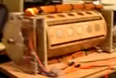 The motor can be a self-runner, but for the coil-shorting demonstration, it was just spun briefly by hand, producing voltage pulses of about 16 volts. When the coil-shorting is switched on, those pulses rise to about 440 volts even though the coil shorting was not the optimum five times at peak (which would probably have raised the voltage pulses to about 1,600 volts). The oscilloscope displays of the test shown on video are:  I’m told that this coil-shorting technique is used in industry but is consider to be a ‘trade secret’. Details of John Bedini’s Window Motor can be found at www.fight-4-truth.com/Schematics.html. Raoul Hatem. Generally, the RotoVerter gives very low input power when not loaded and about a 90% energy reduction when under load. The ideal situation is where there is a constant load as the tuning of the RotoVerter does depend to some degree on the load. However, the RotoVerter performance can be increased very substantially by using the techniques introduced by Raoul Hatem in 1955, which conventional science will not accept because according to current theory, any such energy gain has to be “impossible” and so, cannot happen no matter what evidence there is (web site):  Raoul Hatem’s heretical statement is that using spinning magnets draws in energy from the environment, allowing a system to have COP>1 (ever heard of John Searle’s spinning magnet systems?). His method is to use a motor (whether RotoVerter or not) to spin a heavy rotor disc with 36 powerful rare-earth magnets mounted on it. Then, using an identical heavy disc with magnets mounted on a generator to give a magnetic coupling between the motor and the generator can give not just coupling, but an energy gain as well:  The heavy rotor provides some flywheel effect which helps with the operation of the system. Even with one motor as shown above, there is an energy gain as demonstrated in a recent video demonstration of the effect here where a simple system produces 144 watts of excess power. However, the really big gains are got when several generators are driven by just the one motor. In passing, it may be remarked that there are two separate energy gain systems operating here. Firstly, the rotating magnetic field acts directly on the excess electrons in the local environment, drawing them into the system just as the fluctuating magnetic field of the secondary winding of any transformer does. Secondly, the rotors are receiving a rapid stream of drive pulses, and as Chas Campbell has demonstrated, that draws in excess energy from the gravitational field. Anyway, you will notice that the powerful magnets used have their North poles outwards on one rotor while the adjacent rotor has the South poles outwards. The very strong attraction between these opposite poles cause the generator disc to rotate in step with the motor disc. This process allows many generators to be driven by just the one motor as shown here and in the photograph above:  For ease of drawing, the diagram above shows only eight magnets per rotor disc, but you will notice in the photograph (and in the video) that there are three stepped rows of magnets on each rotor: 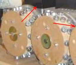 You will also notice that direction of the stepping is reversed on every second rotor disc in order for the magnets to match each other in position as they rotate in opposite directions. The relevant patent on this is FR2,826,800 of January 2003. Hatem has an interesting video here. Lawrence Tseung. Lawrence has been presenting his theory of lead-out energy which indicates that excess energy is drawn from the environment when there is an impact. The method of producing this effect which he has followed is to create an unbalanced wheel and demonstrate that excess energy is produced. It should be stressed that energy is never created or destroyed and so, when he measures more energy in his device than the energy which he uses to power it, energy is not being created but is instead, being drawn in from the local environment. Lawrence has recently demonstrated a prototype to members of the public: 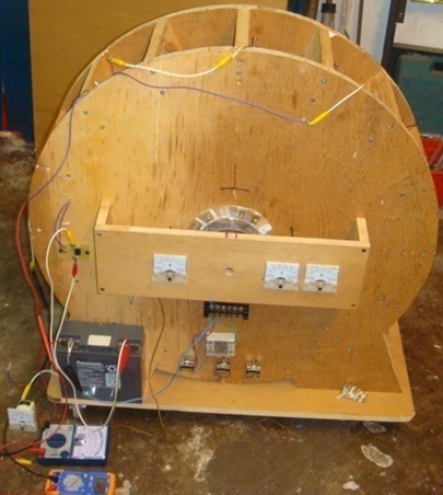 This simple device was demonstrated to have 3.3 times as much output power as the input power needed to make it operate. This is an early prototype which was demonstrated in October 2009 and Lawrence and his helpers are working on to produce more advanced models which have kilowatts of excess electrical power. Mr Tseung remarks: "The Lee-Tseung Lead-Out Energy Theory was first disclosed to the world on 20th December 2004 at Tai Po, in Hong Kong. The Lead-Out Energy Theory basically says that one can lead-out (or bring-in) Energy from the surrounding environment into a Lead-Out Energy Machine. The total Input energy is equal to the sum of the Supplied Energy plus the Lead-Out Energy. For example, if the supplied energy is 100 units and the lead-out energy is 50 units, the device's total Input Energy will be 150 units. This means that the Output Energy can be more than the Supplied Energy of 100 units provided by the person using the device. If we ignore the small loss of energy caused by less than 100% efficiency of the device itself, then the Output Energy will be the whole of the 150 units. If we use 50 of the output energy units and feed back 100 of the output units as the Supplied Energy, then that Supplied Energy can again lead-out another 50 units of excess output Energy for us to use. Thus a Lead-Out Energy Machine can continuously lead-out pollution-free, virtually inexhaustible and readily available energy for us to use. We do not need to burn any fossil fuel or pollute our environment. The two examples of Lead-Out energy which we access are Gravitational and Electron-Motion energy. The Lead-Out Energy theory does not violate the Law of Conservation of Energy. The Law of Conservation of Energy has been used as a roadblock for the so called “Overunity” devices. The patent offices and the scientific establishment routinely dismiss an invention as belonging to the impossible “perpetual-motion machine” category if the inventor cannot identify the energy source of his invention. We got the help of Mr. Tong Po Chi to produce a 60 cm diameter Lead-Out Energy machine in October 2009. The Output Energy of that device is greater than the Input Energy by a factor of 3 times. These results are confirmed by voltmeters and ammeters measuring the Input and Output energies. The Tong wheel has been shown at two Open Shows in Hong Kong (Inno Carnival 2009 and Inno Design Tech Expo) in November and December 2009. Over 25,000 people have seen it. The Better Hong Kong Radio Show has video recorded it, the discussions being conducted in Chinese. At this time, the Tong wheel is at the Radio Studio available for experts to view and examine with their own instruments." The Tong wheel has a diameter of 600 mm, 16 permanent magnets mounted on its rim and 15 air-core coils mounted around it on the stator. There is one position sensor. The coils can be switched to act as drive coils or as energy collection coils: 
With this arrangement, if the positions the switches as shown for ten of the fifteen coils shown here, then they act as drive coils. The sensor is adjusted so that the drive circuit delivers a brief energising pulse to those coils just after the magnets have passed their exact alignment position with the coils. This causes them to generate a magnetic field which repels the magnets, thrusting the rotor around. The pulse is very brief, so very little power is needed to accomplish this pulsing. As mentioned before, any number of coils can be switched to provide this driving force. With this particular wheel construction by Mr Tong, the best number has been found to be ten drive coils. The power pick-up is achieved by gathering the electricity generated in some of the coils as the magnets move past them: 
In this particular arrangement, five of the coils gather energy while ten provide the drive. For the sake of simplicity, the diagram shows the five collection coils adjacent to each other and while that would work, the wheel is better balanced if the drive coils are evenly spaced out around the rim. For that reason, this switching would actually be selected to give five sets of two drive coils followed by one pick-up coil as that gives a perfectly balanced thrust on the wheel. The two diagrams above are shown separately in order to make it clear how the drive switching and the power pick-up switching are arranged. The full design arrangement and the balanced switching are shown in the following diagram which indicates how the full design is implemented on this particular implementation of the wheel design. The sensor can be a coil feeding a semiconductor switching circuit, or it can be a magnetic semiconductor called a Hall-effect device which can also feed a semiconductor circuit. An alternative would be a reed switch which is a simple mechanical switch encased in an inert gas inside a tiny glass envelope. Suitable switching circuits are described and explained in chapter 12 of this eBook. 
Mr Tseung remarks that the large wheel size is due to the fact that the Pulse Force takes time to impart the impulse to the wheel and lead-out energy from the environment into the system. If you want to see this actual wheel, you can email Dr. Alexandra Yuan at ayuan@hkstar.com to make an appointment. The Tong wheel is located at the Better Hong Kong Radio Studio in Causeway Bay, Hong Kong. Just say that you want to see the Lead-Out Energy Machine. The demonstration can be in English or in Chinese. Ideally, there should be a group of at least six visitors with one or more being a qualified engineer or scientist, and you are welcome to bring your own cameras and/or test equipment. It is planned to produce a version which has a 300 watt output, and another with a 5 kilowatt output. Educational kits are also planned. If you decide to replicate this particular design, then to raise the output power level you might consider putting another set of coils around the wheel and either using them as fifteen additional energy pick-up coils or alternatively, pulsing the wheel twice as often. Adding one or more additional rotor discs to the same rotating shaft is also an option and that has the advantage of increasing the rotor weight and improving the effect of the impulses on the rotor. The diameter of the wire used to wind the coils is a design choice which has a wide scope. The thicker the wire, the greater the current and the larger the impulse given to the wheel. The coils are normally connected in parallel as shown in the diagrams. Because of the way magnetic field strength drops off with the square of the distance, it is generally considered good design practice to make the coils one and a half times as wide as they are deep, as indicated in the diagrams above, but this is not a critical factor. This design is, of course, a version of the Adams motor described at the start of this chapter. Although motors of this kind can be built in many different ways, the construction used by Mr Tong has some distinct advantages, so here is a little more detail on how I understand the construction to be carried out.  There are two side pieces which are attached together by sixteen cross timbers, each of which are held in place by two screws at each end. This produces a rigid structure while the construction method is as simple as is possible, using readily available materials which are worked with the most basic of hand tools. The construction also allows the motor to be taken apart completely without any difficulty, transported as a “flat-pack” package and then assembled at a new location. It also facilitates people who want to see the motor taken apart after a demonstration in order to assure themselves that there is no hidden power source.  Each of the cross timbers provide a secure mounting platform for an electromagnet and it’s associated switch. In the implementation by Mr Tong, there appears to be just the one rotor, configured as shown above with sixteen permanent magnets mounted in it’s rim. The magnetic poles of these magnets are all orientated in the same direction. That is to say, the magnetic poles facing outwards are all either South or all North poles. It is not critical whether the outward facing poles are North or South as Robert Adams used both arrangements with great success, but having said that, most people prefer to have the North poles facing outwards. Robert has always said that one rotor was enough, but his techniques were so sophisticated that he was able to extract kilowatts of excess power from a single small rotor. For us, just starting to experiment and test a motor of this type, it seems sensible to stick with what Mr Tong has experienced success. However, this build by Mr Tong is not his final motor but just one in a series of continuously improved motors. The following diagram shows an arrangement which has three rotors attached to a single shaft and while you may choose to construct this with just one rotor, if the cross timbers are long enough, then one or two extra rotors can be added in very easily at a later date.  Here, just two of the cross timbers are shown. The electromagnet coils used by Mr Tong are air-core as that type have the least effect on the passing magnets. However, electromagnets with cores tend to be much more power for any given current flowing through them. In theory, the core should be made of lengths of insulated iron wire as that would reduce power loss through eddy currents flowing in the core, but Robert actually recommends solid metal cores, and as he was the most experienced person in this field, paying attention to what he said seems sensible. The core material needs to be a metal which magnetises easily and powerfully, but which does not retain any of its magnetism when the current stops flowing. Not many metals have those characteristics and soft iron is usually recommended. Nowadays, soft iron is not always readily available and so a convenient alternative is the central bolt of a masonry anchor which has excellent properties:  The shaft of the bolt can be cut quite easily with a hacksaw, but be sure to remove (or file down) the head of the bolt as the increase in diameter has a marked effect on the magnetic properties of the electromagnet core if it is left in place. The bolt shown above is a M16 x 147 mm masonry anchor bolt with a bolt diameter of 10 mm. Some makes of dry-ink felt white-board markers have a rigid body which fits the 10 mm bolt exactly and provide an excellent tube for constructing an electromagnet bobbin. With a core in the electromagnets, the rotor gets additional rotating power. Initially, the magnets on the rotor are attracted to the electromagnet cores, giving the rotor a turning force which does not require any current to be supplied. When the rotor magnets are at their closest point to the electromagnet cores, the windings are powered up briefly and that gives the rotor magnets a strong push away, causing the rotor to spin. There are many different designs of simple drive circuits and it is probably worth trying out different types to see which works best with your particular build of motor. In the same way, there are many kinds of collection circuits for taking off some of the excess power generated. The most simple of these is just a diode bridge, perhaps feeding a battery and charging it up for use at a later time. If you get sophisticated with the collection circuit and just take power off for a very short period of time at the correct moment, the cutting off of the current draw, causes a back-EMF magnetic pulse in the collection electromagnet which causes it to give the rotor an extra drive push – both current collection and rotor drive in one combined package.  Here are two of the most simple circuits possible, one for drive and one for power collection. The drive circuit transistor is switched on by a voltage generated in the grey coil by a rotor magnet passing by. The transistor then feeds a large current pulse to the black coil, driving the rotor on its way. The neon and the diode are there to protect the transistor and a physical layout for this circuit might be:  The 1K variable resistor is adjusted to give the best performance and the On/Off switch is optional. More advanced circuits, such as the one on page 2 - 9 can also be tried and the performance compared. Generally speaking, I would expect a three-rotor version to give a better performance than a single rotor implementation, but experimentation is needed. DC Motor Efficiency Commercially available DC motors are deliberately designed and manufactured to have extremely poor performance. In my opinion, the reason for this is that a properly designed electric motor could easily do away with the need for using internal combustion engines in vehicles and that would not suit the oil companies or their owners, the New World Order cartels. Worse still, electric motors with COP>1 open the way to self-powered free-energy systems and that would never do !! Peter Lindemann’s video is available on the web and I strongly recommend that you watch all of it. I have only just seen it and it presents the basic facts very nicely. In brief outline, present day motors act both as a motor and as a generator of electrical power, but they are deliberately wound so that the power generation is used to oppose the input power and so produce a completely crippled output. During World War II, a German Engineer re-wired a standard electric motor and made it self-powered, that is, it ran and produced mechanical output power without the need for any input power once it had been started. That shows the potential of a properly constructed electric motor with the same size and general structure of any commercial electric motor. The con job which has been run on us for many decades now is to wind the motor in such as way that the magnetic fields inside the motor oppose each other. When a current is passed through a coil of wire, it stores energy in that coil, and when the current flow is cut off, that energy needs to flow back out of the coil and it will do so in the reverse direction. This is sometimes called back-EMF (“Electro-Motive Force”) although many people are not happy with that description. However, no matter what you call it, there is energy stored in the coil and that energy can be used to do useful work. But, the motor manufacturers choose to wind the motor so that instead of extracting that useful power, they use it to oppose a major part of the input power, creating a weak motor which heats up due to the wasted energy. Contributor “UFOpolitics” points out that a deliberate mis-design of electric motors has, for the last 130 years, been presented to us as the only way to make and operate such motors. He states that because the windings are arranged in a symmetrical way, that a braking effect is produced which reduces the output power of the motor by anything from 50% to 90%. That is, a properly wound motor would have anything from twice to ten times the output power for the same input power. This mis-design guarantees that present day motors are always less than 100% efficient and always heat up when run. This mis-design is caused by using symmetrical windings in the motor. Presumably, he did that by adding extra brushes and using some of the windings in generator mode with their output powering the drive windings which were arranged asymmetrically. There was also one other man who achived self-powered re-wiring of a motor, but neither of those men shared their information publicly. Standard motor wiring is quite different and the killer effect is caused by having two windings which face each other, powered simultaneously with currents flowing in opposite directions. This causes a complete conflict between the magnetic fields and that destroys the efficiency of the motor: A very experienced experimenter has started a forum thread on the energetic-forum, both to explain this and to show new and more advanced construction methods and to answer questions and encourage replications and further developments. The forum is here and is definitely worth visiting, especially if you are good with mechanical devices. The experimenter uses the forum ID of “UFOpolitics” and he has produced an animated video in an attempt to explain the basic problems with present day DC electric motors: video. He points out that a problem winding in the standard DC motor looks like this:  The input current for any winding is fed in through a single pair of brush contacts. The generated electrical power “Ec” is not extracted and is forced to oppose the input energy “Ea”, leaving only a fraction of the input power to actually run the motor. It is likely that a motor of this type will only operate at 25% of it’s potential efficiency. “UFOpolitics” has produced and demonstrated a simple way of overcoming this problem while using the existing motor housing, magnets and brush contacts. He does this by extracting the generated electrical power as a useful output and so preventing that useful power being used against the motor’s operation. To implement this, he adds one additional pair of brushes and re-winds the motor coils like this:  Here, one pair of brushes is at the top and one pair at the bottom of the ‘armature’ (the bit that rotates inside the motor housing and provides the mechanical power output). The coils are rewound to form a series of separate vertical coils, connecting to one brush terminal at the top and one brush terminal at the bottom as shown above. The input power is between the terminals on the left and flows through the coil shown in brown. The current flow generates a magnetic field, causing rotation because of the Permanent magnets marked “N” (for a magnet which has it’s North pole facing the coils) and “S” (for a magnet which has it’s South pole facing the coils). The black zig-zag line represents the resistance to current flow of the wire and brush contacts. The coil shown in green on the right represents that same coil at a later moment when it has been disconnected from the power supply and rotated until it reaches that position, at which point, the energy stored in it is taken off as a useful output via the right hand pair of brushes. However, this is just an explanatory diagram and it does not show the very important fact that the discharging coil must not directly face a driving coil, because if it does, then the energy discharge would create a magnetic field which would interfere with the magnetic field of the driving coil and create a major problem. Right, to say that again, any one coil is powered on the left hand side to drive the armature around and provide the output shaft with turning power (“torque”). Then that rotation disconnects that coil from the input power, leaving the coil charged with energy which has nowhere to go. That charged coil continues round until it hits the second set of brushes, which allow it to discharge through a load and do useful work. The really clever part of the adaption of the motor is best seen from above the vertical rotor. If, for example, you were to take a five-pole DC motor apart and remove the windings, the shaft and armature body might look like this:  When making an asymmetrical wound rotor, the windings go like this.  The start of the wire is secured at the top and then fed downwards through the opening “A” and back up through the opening “B”. For the small Radio Shack motor, this winding would be 25 turns of # 30 AWG wire (described as radio Shack ‘red’ wire, with a copper wire diameter of 0.255 mm). The end of the wire marked “FINISH” is not cut, but is taken down through opening “A” and this time, up through opening “C”. For clarity, these continuing turns are shown in a different colour, but please realise that it is the same single strand of wire being used throughout:  The final wire turn goes down through opening “A” and finishes at the other end of the body of the armature. In these views, the wire runs down into the paper, each turn forming a cylinder. This view may give you a better visual picture of what the coils are wound on:  The next step is to connect the START and FINISH wire ends of this V-shaped double coil to the “commutator” slip rings which allow current to be passed through the coil at just the right moment. Seen again from one end of the armature, the connections are like this:  The commutator slip rings are connected further up on the drive shaft and the start of the winding wire (shown previously in dark green) is connected to the top commutator sector in the position shown here. The finishing end of the wire is connected to the corresponding commutator sector at the far end of the shaft – that is, the sector directly in line with the upper sector just connected to the start of the wire. This completes the first of five identical V-shaped coils. The next coil is wound in the same way. The armature is rotated one sector counter-clockwise so that sector “D” replaces “A” at the top and the next coil is wound with the wire starting at the top and going down through opening “D” and up through opening “E”, repeating the same number of turns, and then, without cutting the wire the next set of wires are wound going down through opening “D” and back up through opening “F”. The start of the wire is then connected to the commutator sector which spans between openings “A” and “E” and the end connected to the corresponding commutator sector at the other end of the shaft.. For each of the remaining three windings, the shaft is rotated one position counter-clockwise and the same winding and connecting procedure carried out. When completed, no matter which opening is placed at the top of the view along the shaft, the windings and commutator sector for the wire connections will be identical. 3-Pole Motors The winding arrangement is slightly different for motors which have three poles (or multiples of three poles such as 6, 9, 12, etc poles). For the very simple 3-pole motors, the armature looks like this:  and with this style of armature, the winds are around the three arms, like this:  And as before, the commutator sectors at the top are duplicated at the bottom, allowing separate input and output circuits for each of the three coils. The windings have many turns, filling the available space and each winding is connected to the slip ring sector directly opposite it, like this:  The Start of each winding is connected to the commutator slip ring sector at the top of the armature and the Finish is connected to the slip ring sector directly below it, that is, the sector which is at the same angle as the top one where the Start of the wire is connected. This allows the brushes which press against the slip ring sectors to connect to both ends of each coil in turn as the armature rotates. Three pole motors are particularly powerful and motors with six poles can be re-wound with pairs of adjacent sectors amalgamated to give three larger sectors. Nine pole motors can have three adjacent sectors wound as a single coil to provide the same effect as a three pole motor, and twelve pole motors can have four adjacent sectors wound as a single coil. The positioning of the brushes is important. With the three-pole and five-pole arrangements, the brushes are aligned with the gaps between the magnets which surround the armature. However, the re-wound motor can be ‘tuned’ for improved torque and reduced drive current by adapting the motor housing to allow some adjustment of the position of the brush and commutator slip rings relative to the coils. This adjustment need only be slight as the angular movement of the brushes will be small. It is, of course, essential that the upper and lower adjusted positions move by exactly the same angular amount so that every upper commutator slip ring sector remains exactly above it’s corresponding lower slip ring sector. In other words, the commutator slip ring sector at the top and bottom of each coil, must be exactly aligned vertically so that the electrical connections are made and broken at exactly the same instant The commutator and brush arrangement are shown here in UFOpolitics’ diagrams:  The Commutator brush marked “G” (for “Generator”) takes away the energy stored in each coil and passes it to an electrical load. The Commutator brush marked “M” (for “Motor”) feeds energy into the coil from the battery which is driving the motor. The red and blue stripes surrounding the armature are two permanent magnets. The magnet shown in red has it’s South pole facing the armature and the magnet shown in blue has it’s North pole facing the armature. This creates a magnetic field flowing horizontally across the armature. The five-pole arrangement is like this:  Here, the designation “R/S” stands for “Radio Shack” which is a chain of stores in America. In the forum, that is sometimes changed to “RS” and should not be confused with the large electronics outlet “Radio Spares” whose trademark is “RS”. UFOpolitics has suggested that the cheap 5-pole DC motor available from Radio Shack should be used by experimenters to become familiar with re-winding DC motor coils. Being a cheap product, those motors do not have a particularly high build quality, but they are suitable motors for experiments. Forum members share the details of how they dealt with adapting these and other motors. I have to admit that motor windings and operation tend to confuse me and I sometimes find it difficult to understand what ‘UFOpolitics’ means when he talks about different winding strategies. However, it seems reasonably clear at this early stage of forum development, that his objective is to produce two things: While ‘UFOpolitics’ is very patiently going through many of the possible variations on how a DC motor can be wound and connected, and showing various forum members where they have failed to get some of their windings positioned correctly, he has also shown some of the best ways of connecting a re-wound motor used as a driver or “Prime Mover” as some people like to call it, and a re-wound motor which is to be used as an electrical generator. He shows two important ways for making a very effective Motor/Generator combination, as shown here:  It needs to be realised that these arrangements are not conventional arrangements and that the re-wound motors operate in a different way to motors bought ‘off the shelf’. For this reason, it is necessary to isolate the electrical output to prevent current flowing through the load from affecting the operation of the Motor/Generator combination. This can be done by placing a diode in each of the output lines and charging a capacitor bank which is then used to feed whatever load is to powered. If my understanding is correct, then feeding any cold electricity produced into a capacitor causes the current to become conventional hot electricity. It is not clear if that action is part of this arrangement although the circuitry shown should be used. This is the second version:  ‘UFOpolitics’ comments on these arrangements as follows: As we excite the input of the Motor, the Generator will start producing energy and that additional energy will flow through the Motor Output side because they are connected in series here. Two rectifiers must be connected at both output terminals, Positive and Negative, to avoid back flow from closing the circuit through the load. As the Motor accelerates, the Generator boosts the energy flow which then runs through the Motor augmenting the Output Fields and when the output is loaded then an ‘Engagement’ of both Machines occurs as they start to compensate each other through their output flows. It should be understood that the Output should Capacitor Banked in a dedicated Reservoir. When designing a Generator for a specific, existing Asymmetric Motor machine, it must be understood that Generator Interactions should be considered to run as “Counter Rotation” to the Motor Machine’s originally conceived rotation (which is easily done by just moving brush-lines passing stator bisector angles to the opposite of those needed for a Motor, or alternatively, setting the timing backwards). This will definitively enhance the assisted rotation of both Machines when connected together in this Face-to-Face mode. As I do not find the forum comments easy to understand, I recommend that you visit the forum and read the posts as you may well understand the conversations easier to follow than I do. On the forum, ‘Sanskara316’ states “I have re-wound a small 3-volt 3-pole motor. I used an almost dead, 6-volt sealed lead-acid battery to power the motor. This battery just sits at around 4 volts and if given a load, even a small LED, it’s voltage drops to 1 volt. The re-wound motor started very slowly - barely spinning, then after a minute or two it started to spin faster, and I noticed that the voltage on the battery was slowly climbing. I connected a small LED flashlight to the generating side and it lit up. Now the battery voltage under load is around 2+ volts. It’s been running for an hour now and the machine squeals a lot. It is conditioning the battery and the meter cannot be showing what really is happening. The motor draws 300 ma?? – That’s not possible as the battery just doesn't have that power”. To which ‘UFOpolitics’ remarks: “Well I am glad you have witnessed some of the ‘Effects’... these re-wound motors do recondition batteries...remember, Radiant Energy is taking over the Machine...so Radiant Energy comes out through the Input also… which is the reason why we get high Volts-Amps reading on a meter ...these motors use very small amounts of current and volts. Inside the motor, every coil is being ‘Self-Electromagnetically-Pulsed’ because they auto-disconnect from the power source, then the next coil in the sequence is assisted by the first coil when it has rotated to it’s next position, and so on. The commutator switching has become a ‘Self-Oscillator’ for every independently-energised coil.” ‘prochiro’ says: “I have also replicated the battery-charging events that 'Sanskara316' indicated. I started with a 12-volt 4 Amp-Hour battery which I had been using with another circuit two weeks ago and had not recharged it after using it for hours. It was sitting at 12.40 volts. I took my best-running re-wound motor, plugged it in direct and ran it. The battery voltage dropped to 12.24 volts and stayed at that level for 30 seconds. The battery voltage then started to rise 1/100 of a volt per minute. When it was at 12.27 volts, I disconnected the motor (the total run time was less than 5 minutes). I then let it rest for five minutes. At the end of the five minutes, the battery voltage had risen to 12.43 volts and is still at that voltage now. Just think what a larger motor would do on a big battery bank. Everybody needs to document this test as it proves what ‘UFOpolitics’ said.” New DC motors, and particularly cheap motors, will have brushes which do not mate cleanly with the commutator slip ring sectors and so, when the modification has been made, running the motor for some time allows the brushes to wear in and that raises the efficiency of the electrical connections which in turn, improves the performance of the motor. If you wish to build and test one of these motors, then you can find help and support in the forum with your questions answered and numerous videos and photographs from different experimenters to help you. The Infinity SAV Motor / Generator A Motor/Generator which demonstrates clearly that it outputs substantial power as well as generating its own input power is seen operating at YouTube.  I certainly don’t understand their statement that spinning a magnet past a coil does not produce a force which opposes the passing magnet. However, if this South Korean video is genuine, and it certainly seems to be, then it is a most encouraging step forward. This particular design has 25 rows of 10 neodymium magnets spinning past 250 bi-filar coils of wire and it is demonstrated powering itself while lighting 100 bulbs, driving a fan and operating a heater. The Homopolar or “N-Machine”. This device was the brainchild of Michael Faraday in 1831 and has an intriguing method of operation and a remarkably large output.  The principle of operation is incredibly simple:  If a copper disc is rotated in a magnetic field, then power is developed between the shaft and the outer edge (or any intermediate position). It was then found that the device will still operate even if the magnet is attached to the copper disc and rotates with it - not something which is intuitively obvious. The power output is tremendous with the capability of extracting 1000 Amps but at a low voltage of less than 1 Volt. The power take-off can be from one face of the disc near the shaft rather than having to have a copper shaft integral with the copper disc. This device also works with a magnet just attached to the copper disc and rotating with it. This looks like a very viable starting point to develop a device which can run itself and provide useful additional output, since a motor to rotate the disc will not require anything remotely like 1000A to drive it. The snag is, it is very difficult to provide reliable sliding contacts capable of handling large currents for extended periods of time. The second picture above shows the disc with its outer edge immersed in a bath of mercury. This is sufficient for a brief demonstration at low power but not realistic for a serious working device. It might just be possible to get a reasonable working device by accepting that the current output is not going to be anything like 1000A. Long-life brushes could be made from solid copper bar and spring-loaded against the copper disc in matching pairs so that the brush thrusts oppose each other and so do not generate a sideways load. These could be made in multiple sets for each disc, say four or eight per disc, so that the effective electrical resistance between the brushes and the disc is reduced and the possible current draw increased. Similar multiple brushes could be applied to the central shaft cylinder. Multiple discs could then be mounted on a non-conducting, non-magnetic shaft and their brushes wired in series as shown, to raise the output voltage:  It is said that in India, Professor Tewari used homopolar generators to extract hydrogen from water and that bus services were run on hydrogen as the fuel, but I have not managed to find confirmation of that. The main difficulty in using the design is the difficulty in drawing off the very high low-voltage currents produced without creating a major drag factor which is a serious problem. Bruce DePalma managed to overcome this problem but he assigned his development to the US Military In 1987, three of the Borderlands Science team, Michael Know, Peter Lindemann, and Chris Carson experimented with the homopolar design and found that a much more satisfactory version could be produced. Their version produces sawtooth AC instead of DC and so the output could be fed directly into a step-up transformer. Their design has four ferrite magnets glued between two metal discs, and for additional mechanical strength, copper wire wound around the outer edges of the magnets in order to prevent magnets flying outwards if the glue bond should fail. Their arrangement is like this:  This appears to contradict the “laws” of conventional electricity as there is a very low resistance short-circuit directly across the brushes which pick up the AC voltage output. The output current from a small prototype was estimated at 100 amps. The frequency of the AC is directly proportional to the shaft speed of the motor, but the output voltage was almost independent of the shaft speed of the motor, increasing only very slightly with much greater speed. It was also found that putting the brushes at 90 degrees apart on the metal shaft of the motor gave the same output in spite of the contacts nearly touching each other. This design appears to have considerable potential for construction in a larger size and further investigation. While the operation of these devices looks impossible at first glance, it needs to be understood that copper has some very unusual characteristics when interacting with magnetic fields. This is explained in the web site http://magnetism.vfedtec.com/SpinningCylinder.htm where it can be seen that a spinning copper cylinder exerts a large sideways force on a permanent magnet placed near it. This does not happen with spinning cylinders made from other metals. Nikola Tesla took Faraday’s 1831 design further as can be seen from his 1889 US patent No. 406,968. He remarked that to get any kind of useful power from the device would require a copper disc of very large diameter, or a disc which is spun very fast. A large copper disc would be an inconvenient size, and a high rate of rotation makes it very difficult to get a good, long-lasting, sliding contact at the outside edge of the disc. He also pointed out that current flowed from the shaft out to the outside edge if the magnetic field passing through the disc was in one direction, but if the direction of the magnetic field were reversed, then the current flow would be from the outer edge inwards to the shaft. The same change of direction of the current flow also happens if the direction of rotation of the disc is reversed. Using those facts and considerable ingenuity, Tesla proposed an arrangement where the power take-off is from the axle alone, by using two separate copper discs and magnetic fields which moved in opposite directions. This arrangement has the advantage that it has an output voltage which is the sum of the two separate voltages. This basic concept uses four ring-shaped magnets and two discs of copper, brass or iron. Both of the discs are given a wide flange, as shown here:  The circuit shown here is broken by the gap between the discs and Tesla dealt with that by using a flexible metal belt linking the two discs together:  While it is possible to use the belt to drive one of the discs, Tesla did not use that method. The belt overcomes the need for a sliding contact at the outside edge of the discs and so both sliding contacts are at the axles which is an easy place to have a sliding contact. Tesla shows the contact against the end of the axles as that is just a rotary movement with respect to the stationary contact, but even if the contact pressed against the outer face of the axle, the sliding movement would still be relatively slow. In spite of this clever design from Tesla, I have never heard of anybody building this style of generator in spite of the large currents which it can generate. A developer who prefers to remain anonymous, says “For people who have an interest in homopolar generators of the type experimented with by Tewari, Trombly-Kahn, DePalma and others:” What if there were another configuration to the engineering of a homopolar generator than the standard method of running a magnetic field parallel to a rotating shaft and through a conducting spinning disk? Though someone may have formulated this alternate type of a homopolar generator, I have never read nor am I aware of anyone having put forth this idea nor having constructed any such homopolar generator mentioned below. The below design information is Public Domain information and so anyone is free to construct a device and/or make use of this information however they wish without royalty demands. In principle it is no more complex than the Faraday model. Having made some study of these above mentioned devices by Tewari and de Palma and learning of some of their shortcomings I kept wondering why it is that at this point in time (since the coming of the age of neodymium magnets which were not available in their time) no one has considered their use in an alternate configuration. Neodymium magnets can be had in what is termed as “arc magnets”. These magnets are designed to be mounted on drums or cylinders to serve as poles on a rotor in a motor or generator. The Faraday Dynamo or standard homopolar generator was made such that the magnetic field is parallel to the rotating axle through a rotating and conducting disc. With arc magnets we can mount them so that the field is now perpendicular to the axle, in other words on a drum circular about the axle with one magnetic field directed outward and the other inward to the axle. Let us say the north pole is going outwards and the south pole going inwards toward the axle and then curving out of the ends of the drum as shown here in Fig.1.  At this point it is interesting to note that the axle is serving as a magnet and since the south pole is directed out the ends of the drum the axle itself has become a magnet that has a south pole at each end of the axle. Where the north pole might be in the axle I‘ll leave to the debating society. A tubular conductor is placed over or under the magnets (the magnets can be difficult to mount in this fashion as they will not want to be mounted that way) the charge (also referenced to as a space charge) will separate to the ends of a conducting tube or copper sheet wrapped over or under the set of magnets where brushes at the ends can tap the current when the device is rotated.  This new arrangement opens up multiple manner of possibility. It can allow for a lengthy drum - the addition of added drum segments of magnet sets which should increase voltage. It is should also be possible to mount magnets on the drum that alternate magnetic poles- in common fashion similar to a common motor and use back and forth wiring over the poles faces to multiple voltage, of course this can not be considered homopolar but rather polypolar. The reason for attempting this is to raise voltage to the point that exotic brushes need not be considered as much higher voltages can be achieved. For those not familiar with this form of homopolar generator the reason for rotating the conductor with the field is to overcome the effect of the counter electromotive force of the generator or circumvent undesired effect of Lenz‘s Law. While I do not have the machine tools to make a good homopolar generator I was able to hand make parts that I assembled into a proof of concept generator. I was able to prove to my satisfaction that this tubular type of homopolar generator does work but I cannot say how well. I have reason to think that it should prove just as valid a method as the standard Faraday Dynamo. Anyone with the tools is free to make his own. I would like to learn the outcome of your work. Here are some pictures of my construction:   The builder states that in his opinion, the voltage will be increased if the device is built with a longer cylinder containing more magnets, and so the sliding brushes which take off the output current are further apart. He is also of the opinion that if the diameter of the device is increased that the output voltage will also be increased. He does not have the necessary equipment nor the finance required to develop this further but he invites you to build this design and take the design further. In my opinion, it should be possible to use ordinary rectangular magnets positioned so that they touch along their inner ends and have a slight gap at the upper face all along their length. It should be possible to mount them securely on a non-magnetic cylinder before wrapping copper sheet around them to form the copper cylinder of the device. Art Porter. Art uses an electromagnet with a ring magnet mounted on the core. When the coil is pulsed so as to augment the field of the permanent magnet, Art says that his prototype produces 2.9 times the field strength of the permanent magnet on it’s own. When the coil is pulsed in the direction which opposes the field of the permanent magnet, the resulting magnetic field is zero. This is a very serious change of magnetic field which can be used in different applications. One which Art has implemented is using the arrangement to power a crankshaft motor. Art shows several different motor builds including this one:  With this arrangement, Art states that 95% of the motor power comes from the permanent magnet. Art’s website is here and he has a very interesting, lengthy video showing all of the details here. In the video, Art attempts to apply Ohm’s Law in an attempt to analyse the operation and is puzzled when the oscilloscope readings do not match his Ohm’s Law calculations. He thinks that there is a contradiction between the oscilloscope and Ohm’s Law, which he repeatedly stresses is a law of Nature, and he concludes that one of them has to be wrong. In actual fact, neither are wrong because Ohm’s Law only applies to DC current flow in resistive circuits, and Art is not using steady DC current or a resistive load. Applying short DC pulses to a substantial coil of wire is the equivalent of applying AC to that inductor. Ohm’s Law does not apply due to the inductance of the coil. There is a Power Factor involved and Back EMF voltage pulses, so the oscilloscope readings are what is needed to calculate the input and output powers. This arrangement is almost identical to that used in the Charles Flynn magnet motor described in chapter 1, and very close to the techniques used by Robert Adams in a properly tuned Adams Motor as shown at the start of this chapter. In my opinion, the effect which Art is exploiting would best be used if a large pick-up coil is placed against the end of the electromagnet core and the drive coil pulsed at the coil’s (high) resonant frequency as that will minimise the input power and maximise the output power. Stacking those units in a bank could well produce a very sizeable excess electrical output. Our thanks are due to Art and his colleagues for sharing their research work freely for others to replicate and progress further. Patrick Kelly http://www.free-energy-info.tuks.nl http://www.free-energy-info.com http://www.ffree-energy-info.co.uk http://www.free-energy-devices.com |