|
Using a motor-driven generator has been popular for a long time now. There are various types and styles and there is usually the desire to organise things so that the system is self-powered.
You have the simple, direct-coupled types where a second motor is used as a generator or a mains style of generator is used: 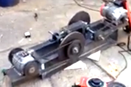 You will notice that two small flywheels are used in this system. Then there is the style used by Chas Campbell of Australia where a large flywheel is used and pulleys allow for control of the speed of rotation as well as for alignment. Chas chooses to have his coupling spread out:  While José Luis García del Castillo prefers a more compact arrangement (which is presumably more difficult to construct and maintain:  And then there is the very rough and ready style used by “Mr Wilson” of Texas where he took an old round table and converted it into a very heavy wooden flywheel by hammering nails into the circumference to form a very rough V shape:  And then there is the most simple looking style where the motor is coupled directly to the generator, which in this case is a motor: 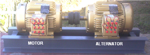 This last version is by far the most difficult to build as the shaft alignment has to be perfect and that requires: 1. The two shafts to be at exactly the same height. 2. The two shafts to be aligned exactly in the vertical plane. 3. The two shafts to be aligned exactly in the horizontal plane. Achieving those three requirements simultaneously requires a skill level which I certainly don’t have. Please bear that in mind when we consider the next design which was built by John Bedini of America. John is an exceptionally talented and able developer. Unfortunately, his designs can look ever so simple but they are usually very subtle constructions as John is very intuitive and knowledgeable as well as being very persistent and patient. His designs usually need fine adjustments in order to achieve the remarkable performances which are routine for him. John never does anything without a reason and his initial build of a motor / generator, described by him in 1984 is dangerous because of the way that he chooses to use it and he states quite bluntly that using his technique can make the lead-acid battery explode. I do not recommend that you try to use John’s design in the way that he does as there is no need for involving a dangerous technique since a useful generator can be made and run perfectly safely. I will try to explain John’s design and then go on to describe a simple version which most people would be able to understand, build and use safely. None of the drawings in this document are to scale and are included merely to aid understanding. It should be noted that John’s design has run quite literally, for years, keeping it’s own battery charged at all times. An American called Jim Wilson built an excessively large version of it and that produced twelve kilowatts of excess power as well as being self-powered. Ideally, we want to build something which is between those two sizes and which has a useful power output. John’s design starts with a DC motor, which in the case of his first prototype is a General Electric permanent magnet, one-twelfth horsepower (62 watt) 12-volt motor which runs at 1100 rpm. That motor is coupled to a small, heavy flywheel::  This coupling arrangement has the difficulty of aligning the motor shaft exactly with the flywheel shaft and a flexible coupling would generally be used by most people as it is very difficult to align the shafts perfectly. The inclusion of the flywheel is said to be in order to keep the motor running well when it is being pulsed rather than having a continuous feed of electricity from the battery. Please understand that John knows far more about free energy than I do. However, I am not sure that I would agree with that assessment of John’s as the motor is designed to rotate 1100 times in a period of one minute and that is 18 times per second and it seems unlikely to me that the armature inside the motor would not have sufficient weight to run smoothly when receiving several pushes per second. I think that a flywheel draws energy in from the local gravitational field (although I can’t prove that and wouldn’t care even if I could). Every particle making up the rim of the flywheel is accelerating inwards towards its axle and that happens continuously when it rotates. Anyway, either way, John has a great working system whatever the reason. In passing, John is so expert with lead-acid batteries that he has tuned his unit so that the battery does not realise that it is powering a motor and that creates a problem because the battery is getting recharged without getting discharged and so needs a protection circuit to prevent it getting overcharged. That is a nice problem to have. The rotating shaft turns a generator to produce a useful output. In the case of John’s prototype, he modified an American office 2-speed fan, using the housing for his own generator arrangement. The generator is a set of six permanent magnets spun in front of six coils of 200 turns each, of AWG 20 (21 SWG) wire of 0.81 mm diameter. The coils are connected in series, effectively making a 1200 turn coil which is pulsed by six separate magnets. Amazingly, the magnets are bonded to an aluminium disc. That seems strange as aluminium has major magnetic properties but the old phrase “if it ain’t broke, don’t fix it” applies and if you decide to attempt a direct replication of John’s generator, then do exactly what he does. The arrangement is like this, although only four of the six magnets can be seen as they are placed in a circle:  The coils have a metal core and Robert Adams stated that experimentation has shown that output coils should have a core whose cross-sectional area is four times the cross-sectional area of the rotor magnets. Robert also stated that the rotor magnets do not have to be exceptionally close when passing the coils and that a gap of 10 mm or so works well. This is an area where you can experiment to see what works best for your particular construction. John’s rotor construction is unusual as the North poles of the magnets bond to the aluminium disc and the South poles face the coils. I have seen the opinion expressed that North poles have four times the effect when passing power collection coils, that South poles have. But as always, if you are going to replicate something, then you do exactly the same, otherwise it is not a replication but instead is a notion of yours (quite possibly a notion that the inventor also had, tested, and found to be no use). The next step for building this system is to arrange the connection of the output power from the generator. This is arranged to have the power going back to the battery for some of the time and for some of the remaining time the battery feeds power to the motor. This leaves me slightly puzzled. The output from the generator is available all of the time, but we seem to be abandoning it for half of the time and that doesn’t seem to make any kind of sense to me. With six output coils and six rotor magnets, each rotation feeds generator power to the battery while the six magnets pass three of the coils, but then, the generator output isn’t used while the magnets pass the next three of the six coils. Huh? Maybe I’m missing something here – perhaps that 180 degrees of unused rotation store extra energy in the coils or a capacitor which John does not show, but that seems unlikely to me. However, John only shows the system running itself and no indication at all of where any excess energy might be drawn from the system, although, presumably, a load could be powered directly from the battery which is powering the motor. Anyway, the best switching arrangement for John has been to use a mechanical switch which acts as a single pole changeover switch mounted on the shaft of the motor (and electrically insulated from the shaft). First, the switch connects the battery Plus through to the Plus of the motor, causing it to rotate, as the battery Minus is permanently connected to the motor Minus. Current then flows from the battery, through the switch and into the motor (although John has his system so well tuned that he says that the battery supplies voltage but gets disconnected before any actual current has time to flow out of the battery). Then, just before 180 degrees of rotation have occurred, the switch opens and then connects the generator output through to the battery, with current flowing in the other direction through the switch. Timing in these systems is generally related to the position of the motor shaft and so each full turn is considered to be a timing of 360 degrees:  From 0 degrees to 100 degrees or less  From 180 degrees to 280 degrees or less For this switching, John uses this arrangement which is known as a commutator:  As the inner circle is electrically connected to the dark (copper) strip at the top which spans approximately 100 degrees around the circumference, sliding contact 1 is electrically connected to sliding contact 2 in the position shown above. When the disc rotates so that the copper strip no longer touches sliding contact 2, there is a period of about 80 degrees of rotation where there is no connection between any of the contacts. When the copper strip reaches sliding contact 3, then sliding contact 1 is connected to sliding contact 3. That arrangement is the equivalent of a single pole changeover switch. That switching system is mounted on the shaft of the motor but insulated from the motor shaft to avoid short circuits through the motor itself. However, contacts 2 and 3 shown above are adjustable in position so that the duration and timing of the pulses can be altered to some degree. John says that he tunes his design by adjusting the feedback to resonate with the ions inside the battery. In my opinion that is highly dangerous and I would not for one moment suggest that you do anything remotely like that. That is why John recommends the use of protective clothing, eye shields and enclosing the battery in a very strong box to contain the acid if your fooling around with battery acid resonance strays into a danger area. It is not at all necessary to do what John does. How he does the adjustment is by putting a variable capacitor across the generator output and he adds a meter to show how his adjustments are affecting the operation, both when he alters the setting of the capacitor and when he alters the position of the commutator brush which feeds power back to the battery. The arrangement is like this:  So, to clarify the operation, the constructor is expected to adjust the variable capacitor and the duration and timing of the commutator switching on the motor shaft to get the exact combination which resonates with the acid in your particular battery. There is no indication of how these adjustments are best made or exactly what the meter would show when the optimum setting has been reached. I personally do NOT recommend that you try to achieve battery acid resonance and I stress that if you choose to do so, then the results of your decision are yours and yours alone and nobody else is in any way responsible for what happens. If you succeed in replicating John’s exact system, then congratulations to you, but please be very clear that I do not recommend it. Later on in this document I will be showing you a very effective and safe system for constructing a Motor - Generator system. Alright, so far we have covered the general outline of a Motor - Generator system, from the most simple version using two motors with one being the ‘generator’ through to the very sophisticated Bedini design. We now have to choose which version is easiest for us to build and which will give us the greatest output power. However, let us consider some practical details. I would suggest that we avoid trying to align shafts exactly and instead, use pulleys and belts as those are easier to align correctly as well as giving the ability to gear the speed of rotation up or down (although in John Bedini’s case, the ratio is 1-to-1). In these days when 3D printers are becoming widespread, if you can’t find the pulley you want, then a friend with a 3D printer can make one for you (3D printer maximum diameter is likely to be 220 mm). A friend who owns a lathe or alternatively a local steel fabrication company could also make any pulley wheel that you want. If those options are not possible for you, then you can actually make a pulley wheel by hand – a fact which in these days of automation, may not occur to you. Making an accurate flywheel sounds difficult, but there are many things on the market which can be adapted to act as a flywheel. For example, dumbbells are low cost and very suitable:  These come with a mounting bar and clamps and using only half of the bar, can give 5, 10, 15 or 20 kilograms on the half shaft. It should also be possible to convert one of the smaller discs into a pulley if you feel like doing that. You can also get a flywheel made up by a local steel fabrication shop, or a friend with a metal-cutting lathe could make one for you. If you are inclined to put dumbbell discs on to a threaded steel rod or plain steel circular bar then the alignment can be helped by using a stack of the weights and some electrical tape. Decide where you want the first disc to be located on the bar. That is, what length of bar you want sticking out of the disc. The thickness of one disc further along the bar towards its end, wind electrical tape tightly around the bar and keep winding until the tape is a reasonably tight fit in the central hole of one of the discs and position a disc there. That places the rod central to the hole in the disc. Just above that disc put a piece of card which has a hole which is a tight fit on the rod and is wider than the hole in every direction. Measure all of the discs of that size which you have and measure along the bar to where the last disc would be if all those discs were placed in a stack on the bar. Wind more electrical tape to form a plug for the disc hole of the top disc in the stack. Supporting one disc on a pile of books or some other suitable packing which allows the axle shaft to be vertical, put one disc on top of the card on the rod and fill in around the shaft with epoxy resin. Then place all the other discs on the rod to form a perfect stack, using a straight edge all around the stack to ensure that the discs are exactly on top of each other. The electrical tape rings at top and bottom give exact alignment provided that the discs are all aligned exactly:  When the epoxy has gone hard, you can remove the upper discs and the bottom disc and remove the card which will be stuck to the epoxy and which will need to be cut away and sanded smooth. Treating the glued disc as the bottom one, as many discs as you want can be epoxied to the axle shaft in a single operation, ideally keeping an extra disc at the top centred with a ring of electrical insulation tape. Use slow setting epoxy and be sure to fill all of the gap between the axle shaft and the inside of the discs with no air voids in the epoxy and make sure that the stack of discs are exactly aligned, checking all around with your straight edge:  When the epoxy has set, you end up with an accurate, properly centred and squared flywheel:  If you are careful to get the centring and perpendicular angles right, it is possible to use a deep circular biscuit or sweets tin as a mould and with a central hole in both the bottom and the lid, fill the tin completely with a mortar mixture of sand, cement and water, using the lid to give you the exact alignment of the shaft which could be a threaded rod or a steel or brass bar:  If using that method of construction, you might like to paint the tin if you are not keen on the manufacturer’s decoration of the container. But, no matter what the flywheel looks like, the important thing is that it is balanced and aligned squarely so that when it is spun fast, there are no wobbles or wavering of the flywheel edge as that generates stress on the mountings. The flywheel axle should not be less than 10 mm diameter steel and anything up to 20 mm would be good. Consider the available pulleys and buy what you need before choosing the diameter of the axle. www.beltingonline.com and others have a wide range of pulleys. Please remember that your drive motor will need a pulley which is made for a very different shaft diameter. It would be nice to take advantage of the energy gain available from having different pulley diameters on the flywheel shaft and the generator shaft if that is possible, but if replicating John Bedini’s design, keep the pulley ratios exactly the same. As the flywheel is the biggest and heaviest thing in this construction, we start with it. We use a thick base board for mounting the various items, and we need powerful brackets to support the flywheel axle, which should be mounted in ball or roller bearings. We want the axle to be exactly horizontal so that there is no sideways force trying to push the axle through its bearings. Common bearing sizes in Europe are:  These bearings have a rubber seal to keep dust and dirt out of the grease packed around the ball bearings inside and that spoils the free movement. One way to overcome this has the bearing outer ring clamped stationary and an electric drill used to spin the inner ring until the movement becomes low-friction. An alternative method is to discard the rubber seals and remove the grease by immersing the bearing in paraffin (known as ‘kerosene’ in America). Then the ball bearings or rollers inside the bearing are lightly oiled to give a very free-running bearing. As our bearings are on an axle which is supporting a heavy flywheel spun by a motor, the bearings should wear in reasonably soon even if they are not made free running beforehand. The next thing to do is to make the supports for the flywheel. When the flywheel is spinning it has a lot of energy in it, so we want the flywheel supports to be robust and so I suggest using material which is at least 9 mm thick and preferably thicker than that. Measure the diameter of your flywheel – probably 200 to 250 mm. Divide by 2 to get the radius “R” and add 30 mm to R as the height which the flywheel will be above the base board. Mark your material one and a half times R in from the edge and a point R + 30 mm above it. That is to be the centre of the axle. Draw a line 80 mm long at a height of 50 mm above the axle, and join the ends to the base like this:  Mark the diameter of your bearing centred on the axle point and then cut out that circle using a coping saw or a jigsaw, being sure to keep the blade perpendicular to the sheet material. If possible, stay slightly inside the circle and then use a wood rasp or coarse sandpaper to produce a perfect circle of exactly the right size so that the bearing is a tight push fit in the hole. Next, measure a distance of 1.5R + 10 mm (if your flywheel has a diameter of 200 mm then this distance would be 160 mm) in from the edge of a sheet of material and in a distance of 60 mm and mark that point as it is the axle position for the second side support:  Mark a bearing circle, cut it out and insert the second bearing into that hole. Place a piece of axle material (or a length of dowel of exactly the same diameter) in the bearing and position the first side so that the axle material passes through both bearings, aligning them exactly. Mark around the edges of the first side, being very careful when marking the edge which will become the base of the second side:  Cut out the marked lines and work the bottom edge very carefully to make it exactly the same as the first side as that ensures that the axle will be exactly horizontal. Attach one side to the base board using a piece of timber 50 x 50 mm x the length of the side. Attach a similar piece of wood to the bottom edge of the second side and attach it firmly. Pass the axle through the first side, then thread the second side on to the axle and attach the second side to the base board:  Using a belt and pulley link between the drive motor and the flywheel allows the link to be constructed by the average person, however, great care is needed to get the alignment right. First, the pulley wheels are attached to the flywheel shaft and the motor spindle. Then the drive belt is looped over the pulleys and the motor moved to make the belt fairly tight. Parallel lines drawn on the baseboard makes it easier to get the axis of the motor and the axis of the flywheel exactly parallel. You can then move the motor slowly forward to where it is clearly in the wrong position. Mark that point. Edge the motor slowly back until it is again clearly misaligned. Mark that point. The correct position will be very close to the position half way between those two marks. Use a set square (or fold a piece of paper to form an exact right angle) and mark the base board exactly underneath both sides of the flywheel pulley and draw two lines at right angles to the flywheel axis, going through those two points. If the motor is aligned correctly, then the belt should be exactly above and between those two lines:  When the motor is positioned exactly, hold it in position and mark the positions of the retaining bolts or screws. Removing the motor, drill holes if using bolts or very carefully start the retaining screws into the base board. Then replace the motor and bolt or screw it in position with the drive belt running over both pulleys. John Bedini’s design calls for the generator rotor to be directly attached to the flywheel shaft. This is an aluminium disc with magnets attached to it. As the disc rotates very fast, the magnets need to be very firmly attached to the aluminium. In spite of the fact that aluminium has a major damping effect on magnetic fields, magnets do not stick to aluminium and so a strong mechanical bond is needed. John’s drawing shows the magnets inset into a thick aluminium plate. That is not impossible, especially if small diameter magnets are used, but the magnetic field will be different if the magnets are surrounded by aluminium on all sides except their South pole faces. For example, if backed by aluminium and encased in epoxy resin will produce a different shape of magnetic field, and although that form of construction is much easier, I suggest doing it the way that John’s sketch indicates. If you have a drill press, you should be able to drill accurately enough to make construction easy. Otherwise, as we want a perfectly balanced rotor for high speed rotation, we can drill the axle hole and then measuring out from the hole, mark the edge of the disc and then cut it out. Neodymium disc magnets of 10 mm diameter and grade N52 would be convenient as a 10 mm diameter drill bit fits into most household drills and the diameter of the corresponding coil cores can be 20 mm to give four times the cross-sectional area of the magnet. The rotor can be constructed like this:  Here, two 5 mm thick discs of aluminium are bolted together and to the flywheel pulley, being careful to ensure that the bolts are in positions which balance the rotor disc. The red strip under the magnets indicates glue with “Impact” Evostick being the preferred glue as it is very powerful and sticks to smooth metal better than epoxy does. The blue strip indicates a thin sheet of rigid plastic covering the rotor face and enclosing the six magnets. Following what Robert Adam said after years of experimentation, I suggest that there is a 10 mm clearance between the face of the magnets and the coil cores which they energise. The coils have 200 turns of 0.8 mm diameter wire and being power gathering coils, it would be normal to have them 50% wider than they are deep as that gives a better sweep of the rotor magnet flux through the coils. In John’s design, all of the six coils are connected “in series”, that is, in a chain and if John’s documentation shows his system correctly, then there is no rectification or storage capacitor. However, as the generator power is being fed back to a battery which has definite Plus and Minus connections, I personally would use four UF5408 diodes in a bridge, feeding a 35-volt 22000 microfarad capacitor. Please understand that I do not recommend that you build John Bedini’s acid pulsing design as this document will go on to describe a highly effective and much safer motor-generator design. Let me remind you of what John Bedini says in his document: “I must give a very stern warning at this time that if the voltage developed is too high, the battery will explode. Use the utmost care. Test setups in my lab have proved that this can be dangerous. Do not build the device and experiment with it unless you know what you are doing. The ions in the electrolyte are being stressed. The electrolyte in the battery goes wild and the ions race backwards giving off hydrogen and oxygen gas. I must make a stern warning here. The time of the stimulating pulse is very important. If the time is too long the battery will burn itself out. If the pulse time is too short the battery will never recover its charge. We must remember that, if the battery is applied to the energiser longer than normal, we must burn up the excess energy to keep the battery cool. The problem becomes one of an embarrassing excess of energy, not a shortage“. So, let me stress again that although John’s system has a flywheel, it is not primarily a device for extracting energy from gravity. While it has an electrical generator it does not feed the energy generated continuously back to the battery to recharge it. Instead, it is a system intended to push resonant pulses into a lead-acid battery to make the battery electrolyte behave in a way which is very far removed from the way that a lead-acid battery is expected to perform. As I have already said, I do not encourage you to do that as I consider it to be both dangerous and unnecessary. There are alternative ways of using this equipment. The flywheel axle could extend through John’s generator rotor and have one or more other rotors mounted on it, energising additional stator coils. The commutator could be scrapped and a battery voltage sensing switch used to recharge the battery conventionally (and safely) from the generator and when fully charged again, switch to charging a second battery. The flywheel could be geared differently, spinning a separate generator with an increase in rotational speed due to the flywheel axle having a larger pulley than the pulley on the generator. However, let me suggest a method to experiment with. The pulsed wheel system described in chapter 17 has a proven output which is three times greater than the input needed to make it operate. The drive for that wheel is by coil pulsing which is not affected by the Lenz Law effect and so is efficient. If we use an ordinary commercial motor to drive the rotor, then we will have to accept the drag described by Lenz. However, John Bedini is undoubtedly very experienced and you will notice that in his design he drives his motor with pulses:  And in the suggested pulsing diagram the pulses powering the motor are only 28% of the time, which means that the motor is not being powered for three quarters of the time. That fact reduces the current needed to keep the generator running. The recharging pulses applied to the battery are only applied for about one third of the time. Mind you, John is using those battery-charging pulses to achieve resonant charging. It may be that as each output coil is disconnected when every second magnet passes by them, that may store additional energy in the coil, making the following actual output pulse more powerful. Although John’s designs are frequently based on subtle physical arrangements, I suggest that we do not actually attempt to follow his design exactly, so please understand clearly that the following description is not an attempt to replicate John Bedini’s design directly, but instead to create a somewhat similar configuration . It would be really nice to eliminate the battery in spite of the fact that John views the battery itself to be a free-energy generator. So, I would suggest that we dispense with the commutator switching and use an ordinary “Pulse-Width Modulator” (“PWM”) which is often called a “DC Motor Speed Controller”. While we are testing the device, we will use a battery although we aim to operate without it when the system is completed. The initial arrangement is like this:  The 12V battery power supply to the motor passes through the “PWM” controller which switches the current On and Off many times per second. The ratio of the On timer to the Off time is called the Mark/Space ratio and it controls the amount of power fed to the motor. The John Bedini arrangement has just six magnets and six coils, but for this application I suggest using twelve magnets and twelve coils. The first step is to try to get the system running on part of its own output. In this case we are not trying to feed the highest possible voltage spikes into a battery, but instead are trying to generate a suitable power supply for the motor. For this, we take the output from one coil, rectify it with four 1N5408 high-speed diodes and feed the output into a capacitor. A voltmeter across the capacitor shows what voltage is being developed. As the output voltage is almost certainly less than the motor needs, the coil is replaced with two coils connected in series and the voltage measured again. If, perhaps, it takes four coils to get to the motor voltage or higher, then the motor input is quickly switched from the battery to the coil power supply from the four coils. The coil output is probably not sufficient although adjusting the PWM setting might be able to compensate for that. After all, if it can run on its own output, then we really don’t care how efficient or inefficient the motor drive is as long as it works. However, assuming that no PWM setting allows the motor to continue running, connect four more coils in series and put them across the first set of four coils. Be sure to connect the two sets of coils with the finish of coil 1 connecting to the start of coil 2, the end of coil 2 connected to the start of coil 3, etc. Connecting the coils in series raises the output voltage fed to the motor and connecting the two chains in parallel raises the output current. Get the motor speed up again using the battery and then try again with the eight coils. If necessary, the PWM controller can by bypassed and the coils connected direct to the motor. If the motor runs okay with that arrangement, then you have a self-powered generator and the four remaining coils form a free-energy electrical output. If it is found that all twelve coils are needed to keep the motor running, then either or both of the next two options should produce success. You can raise the voltage from every coil by increasing the number of turns on each coil. I would suggest doubling the length of wire in each coil. And/or put an identical rotor and stator arrangement on the other end of the flywheel shaft, giving you an additional twelve coil output. Please remember that this is only a suggestion and has not been built and tested at this time. If you do build and test it, then please let me know how you get on at engpjk (at) gmail (dot) com. The diode bridge can be constructed without needing to solder as ordinary electrical connector strips can be used:  Here, we have the connections for using one coil, two coils or three coils although any number of coils connected in series can be used. Patrick Kelly http://www.free-energy-info.tuks.nl http://www.free-energy-info.com http://www.free-energy-info.co.uk http://www.free-energy-devices.com |