|
This is a fast-moving field of research and development, and one where a single person working alone, can outperform research establishments with unlimited budgets and many staff members. If you believe that the answers given below are inadequate or incorrect, then please tell me as this is definitely a learning process for all of us.
Topic: What to Build I am regularly asked to recommend a device for someone to build. This is an impossible task as the person asking never says in which part of the world he lives, how much money could be used in the project, what tools are to hand, what workshop space (if any) is available, what local supplies of materials is like, whether the home is in a city or an isolated remote place, local assets like a shoreline, a fast-flowing stream or lots of sunshine all year round, how much ground space is available, what his skills are, etc. etc. What should be realised is that a small group of friends can achieve a great deal. If one person likes working with engines and another can fix television sets and a third can weld, or Е whatever. By working together, they can achieve a great deal and benefit both themselves and their friends, not to mention having a good deal of fun in the process and ending up with a great sense of achievement. We should not dismiss the various forms of renewable energy such as wave power, RAM pump, solar panels, wind power, biomass and the like. Granted, they do not always provide power all of the time, but if they provide most of the power you need for most of the time you need it, then that can be a considerable saving on your present power costs, so you should consider the devices covered in chapter 14. One possibility is to use a RAM pump with a fast-flowing stream, to pump water up into a water tower over night, and use the tank of water to power a turbine driving an electrical generator when needed.  If you have the space and the sunshine, then a parabolic mirror can focus the sunshine, produce steam and drive a generator, a mechanical drive, a pump, or whatever else is needed. 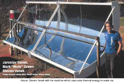 If you are lucky enough to have access to a small section of coastline, then using either wave power or tidal power gives a major amount of power each year with even a simple low-tech construction like this:  It is not necessary to "go for broke" and aim at a device which will completely do away with your power needs for evermore. Initially, it can be a major step forward to produce a device which reduces your energy bill by a good deal and later on, progress to an additional system which makes you fully independent of others. For example, it is perfectly possible to drive a RotoVerter (chapter 2) with a solar panel: 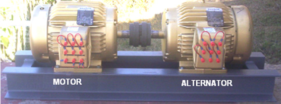 The output is much more powerful than the input from the solar panel and can be used to run power tools, charge batteries or perform other useful tasks at effectively no cost at all. The Frenette heater (chapter 14) does give significant heat output for the modest power input needed to spin the central shaft. It is a simple construction well within the capabilities of most people, and it could be driven by a solar panel if you live in an area where it is cold and sunny. As the array of discs spin, the vegetable oil inside the cylinder gets heated and pushed upwards and outwards, flowing through the radiator tubing, heating the house:  There are many high-performance alternatives which need special skills or equipment to build, but these can be found and constructed by those people who have above average skills and workshop facilities. Devices which can provide power at any time, and at any location, include running a standard electrical generator with water as the only fuel (chapter 10). Strictly speaking, the generator runs on energy drawn from the environment and not on water which itself is not a fuel, but as water is fed to the engine, it appears as if the water is a fuel although it actually is not a fuel. 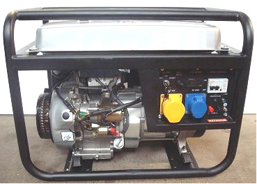 While it is perfectly possible to run this type of generator with water as what appears to be the only fuel, it must be realised that a generator of this type produces noise which will not be acceptable for neighbours if the user lives in a congested city environment. Admittedly, a suitable housing with many carpet-covered baffles would allow good air flow and cooling while reducing the noise to very low levels, but generally speaking, this is a solution for people who like working with internal combustion engines and who live some distance away from other people. The Adams motor (chapter 2) when accurately built, can produce eight times as much output power as the power needed to make it operate. This is a good energy gain and the device is not difficult to build:  Another device which is not hard to build is the Charles Flynn magnet motor (chapter 1):  And if the electronics used to drive it is something which you have not come across before, then chapter 12 shows you how to understand and make these kinds of electronic circuits. A motor of this type can be made to produce any amount of power. Flynn's prototype revved at 20,000 rpm driven by just an ordinary 9-Volt dry cell battery. A big advantage with a motor like this is that you understand exactly how it works, and as you built it in the first place, if it ever breaks down, then you can fix it. Another possible simple project is the Kundel magnet motor (chapter 1). Using just a simple rocking arm movement, powerful shaft rotation is produced. That rotation can be used as a mechanical drive, or to spin magnets past wire coils to produce electricity:  This motor operates by moving the magnets on the rocker arms, away from the rotor magnets when they would oppose the rotation and closer to the magnets on the next rotor which would promote the rotation. The rate at which the loudspeaker cone electromagnet is driven by an electronic circuit, controls the speed of the motor. Another device which can supply extra power is John Bedini's pulsed flywheel (chapter 4). The objective is to apply a pulsed drive to a heavy flywheel. Each pulse acts as an impact, providing excess power to the flywheel. John had a small one of these running in his workshop for more than three years.  The DC motor is pulsed by a simple electronic circuit and the flywheel spins permanent magnets past a circle of coils of wire. The voltage generated in the coils is converted with four diodes to produce a pulsing DC voltage which can charge the battery and do additional work as well. The output from a device of this nature depends on the size of the device. Jim Watson built one which was twelve feet high and he got 12 kilowatts of excess power from it. Obviously, I would not suggest that you build one as big as that, but perhaps one of say, three feet in diameter might have a very useful output. You have the option of wiring the coils in a chain in order to have a higher voltage output. If you do that, then have the same number of coils as permanent magnets so that they all pulse at the same moment. Alternatively, if you want to use magnets mounted with every second one having a different pole facing outwards and still have the coils in a chain, then have twice as many magnets as coils. A similar wheel-pulsing method is used in the water-jet generator (chapter 4) which looks like a very simple thing to implement. Here, a jet of water provides a jerky drive to a wheel when the jet of water hits paddles attached to the rim of a wheel, geared through to an electrical generator.  YouTube has a video showing this arrangement in operation. If you decide to build it then please arrange for an external change-over switch located in a dry area outside the box for switching the pump over from the mains supply to the output from the generator as that is not something which should be done with a plug and socket in a wet area. One of the most straightforward projects would be replicating Chas CampbellТs flywheel system. Perhaps an arrangement like this:  Or if you prefer, an arrangement where there is more than one flywheel, again, keeping the flywheel shaft input drive pulley larger than the output pulley on that shaft. Moving to a somewhat more difficult, but quite possible project. Dr Scott Cramton's version of Dave Lawton's electrolyser (chapter 10) is capable of generating a serious HHO gas output of 6 litres per minute of high quality gas for a very small power input.  This project needs patience as each of the tubes needs to be filed down so that they all resonate at the same frequency. Some minor electronics needs to be built and the pipes either conditioned or alternatively, insulated. The gas output can be used for heating, welding, cutting, cooking, boosting a vehicle or running a generator on water. If you decide to start some project, then whatever project you pick, the most important thing is that it should be one which interests you. You will notice that the projects suggested here generally have moving parts which make it easy to see how the device is operating. The more difficult projects where there are no moving parts and meters need to be used can be left for a later time. If you decide to build something, then let me wish you good luck with your project. A Matter of Opinion This eBook is just a sharing of the information which I have come across during some years of investigating devices which are loosely described as being Уfree-energyФ devices Ц a description which some people dislike because if costs money to construct or purchase a device which can produce useful work, even if the device appears to be self-powered. I am not an expert in the subject and so I have attempted to present the information in a direct and factual way. However, I am regularly asked for my opinion on various devices and which one is best suited to some particular person, so, reluctantly, I will share some personal opinions on a selection of devices. Please understand that the following is just my opinion and could very well be completely wrong. Your level of interest in any particular device depends on your background and whether you are interested in a small device which proves that free-energy exists and can be harnessed, even though the output level is very small. Or if your objective is to obtain a device which can reduce your expenses. Or if you just want to investigate the subject for the sake of general interest. So, we have a wide range of different devices and a range of possible interests, so an attempt has been made to divide the devices into categories based on ease of construction and the output power levels produced by each device. Please bear in mind that there has been a very high level of opposition to any of this type of information becoming well-known and so, information on each device tends to be limited, and while half a dozen devices may well be offered for sale in 2013, at the present time few are commercially available, leaving you to build your own or get a friend to join with you in the construction, which is actually a very good idea as small groups of people can have a very wide range of skills. Devices which are the easiest to build The Magnetic Frame of Lawrence Tseung (chapter 3) The Transformers of Thane Heins (chapter 3) Stephan LebenТs adaptation of the Flynn Magnetic Frame (chapter 3) These three devices have no moving parts and their performance has to be determined by measurements of the input power and the output power. They all operate by passing a fluctuating magnetic field through a frame, which is typically made from thin strips of laminated steel. These devices are limited in their power levels by the amount of magnetic flux which can be carried by their magnetic frames, and to a much lesser extent, by the maximum current which can be carried by the coil windings placed on those frames. Once the core reaches magnetic saturation, applying a stronger magnetic field to it has no effect at all and just wastes the additional power. So, in order to get any form of powerful output, the magnetic frame or core needs to have a high magnetic capacity, which typically means that the frame has to be big, which in turn, means it will probably be heavy and it may be expensive. Using specialised materials for the core could make a major difference, but most constructors will not have access to any of these nanocrystalline materials. When properly constructed and operated, these devices can certainly show you that COP>1 is definitely possible. However, as the results are based on measurements, it is generally difficult to convince anyone else as many people will presume that you are operating a hoax as they have always been taught that any such operation is УimpossibleФ as there is no such thing as Уa free lunchФ. If you do want to comment on the input and output power levels, then be sure to measure the DC voltage and the DC current on both the input and the output as it will be argued that any form of waveform will give measurement errors. The most convincing thing is if the device supplies itТs own input power as well as supplying some additional item, even a single LED. Where the COP is greater than 1, this should be possible, but to keep the device operating steadily, I suggest that you use a voltage-stabilised circuit to supply the input power as that prevents a runaway situation where increased output power produces increased input power and a positive feedback is created which could lead to the almost instant destruction of circuit components which have been driven well past their rated values. Clemente FigueraТs Split Transformer (chapter 3) The Figuera split transformer is exceptional in that it is completely free of the usual crippling Lenz-Law effects and it has the capability of outputs of several kilowatts. The details have been lost for more than a century and only recently been made available, so considerable experimentation is needed but the possible results are spectacular. If electronics does not appeal to you, then using mechanical switching like Clemente did, is a perfectly feasible method of construction. If you want to supply the input power from part of the output, then I would recommend using a stabilised power supply to ensure that only your chosen voltage is supplied as input power. Lawrence TseungТs УFLEETФ Toroid (chapter 5) This is a very easy device to construct and use, but itТs output power is very small. Developments are in hand and I have been told of a version which can run at one kilowatt. The presently known versions appeal enormously to many people who are intrigued that an almost totally exhausted single dry cell battery with far less than one volt, can charge a 6-volt battery or light LEDs for long periods. While this is definitely a СfunТ device, it is unlikely to convince anyone that Сfree-energyТ exists. A one-kilowatt version would be a very different matter. The Aerial Plate System (chapter 7) This is also very easy to construct and being a modular system it has the advantage that it can easily be expanded to give substantial power outputs. This device is based on a Nikola Tesla invention and it has nothing to do with radio transmissions as it picks up ambient energy from the environment. While it can be used to charge batteries, it might also be used for direct power supply if suitable control circuitry is constructed for it. It needs a very high aerial and an extremely good earth in order to perform properly. John BediniТs Simple School Girl Battery-pulser (chapter 6) AlexkorТs Solid-state battery-pulsers (chapter 6) These devices can be very effective in what they do but they are not likely to convince anyone of COP>1 operation. Ron Pugh of Canada has achieved COP=13 with his implementation of the Bedini device running on 24-volts. It is difficult to demonstrate the actual performance as batteries are capable of getting a false Уsurface chargeФ which shows a high voltage but does not indicate a genuinely high level of recharging for that battery as the voltage will drop rapidly when driving a load. The only reliable way to assess the state of charge of a battery is to make it drive a load and observe how long it can sustain that load. The most recent, very-simple, solid-state Alexkor circuit has a COP=12 performance. The Bedini pulse-charger has an impressive spinning wheel or rotor, but itТs usefulness is severely limited as it can only charge batteries which are not being used to power a load. That means that itТs charged batteries are only occasionally available, or two sets of batteries are needed, one for use while the other set is being charged. Ordinary batteries are not all that useful as their life is severely shortened if they are discharged in less than a 20-hour period. Joseph NewmanТs Motor (chapter 11) This is a particularly easy device to build and one which had an experienced technician considerably bothered by itТs performance (as shown in Joseph NewmanТs book which can be downloaded from www.free-energy-info.tuks.nl) as he could not explain how it could possibly perform as it does. However, the amount of power from any reasonably-sized replication will be low. Internal Combustion Engine Boosters (chapter 10) Simple boosters such as the УSmackТs BoosterФ can be built quite easily and they can improve the burn quality of the standard fuel used in an internal combustion engine very considerably, reducing the unwanted emissions and raising the mpg figures by a typical amount of 20% to 40%. While building and using a booster, the actual installing of one in a vehicle does require some basic vehicle knowledge and a few basic tools. Dietmar HohlТs Magnet Motor (chapter 1) This motor has been replicated and proven to work. Given a little care when constructing it and angling the stator magnets as shown gives a considerable improvement in the power available. However, as shown with just one V-set of magnets and one cylinder of stator magnets, the power is not that great although it demonstrates conclusively that permanent magnets can be used to provide power and demonstrate Уperpetual motionФ which is so much feared by УscientistsФ because it shows that their pet theories are, at best, incomplete and at worst, completely wrong. To get some power from this motor design, you need to use a larger diameter drum with two, three, four or five sets of V-magnets around itТs circumference, and possibly more than one set of magnets along the length of the drum. The number of magnets involved in even the minimum arrangement is quite large. Ben TealТs Motor (chapter 1) This motor design is very, very simple and the first version was built using wood and it proved to be very effective, having a two-inch (50 mm) diameter drive shaft. Ben found that he was unable to slow or stop the motor by grasping the drive shaft as the motor was just too powerful. This motor has not been shown to be COP>1 but I wouldnТt be surprised if is. Don KellyТs Magnetic Motor (chapter 1) I have never heard of anybody building this design. It has the potential for serious COP>1 operation as the driving power comes from the magnets and only a small amount of power is needed for the motors to move the stator magnets. I see synchronising the motors as being a potential problem and so would suggest that using only one motor to drive all of the stators as being a sensible option. The motor speed during start-up can be controlled manually with a DC Motor Speed Controller and then the setting just left when it is running at full speed. It could be used to drive sets of magnets between coils to generate electricity and that output boosted substantially further with the coil-shorting method described in chapter 2. Stephen KundelТs Magnetic Motor (chapter 1) This is a very simple and direct method of getting permanent magnets to provide continuous drive with just a very low electrical input used to change the location of the stator magnets in much the same way as in Don KellyТs motor design. The movement is very simple as it is just a rocking movement, driven by the mechanism used in a loudspeaker. As there can be as many sets of rotor and stator magnets on any drive shaft, the power of this design can be substantial. Raoul Hatem's Magnetic Coupling (chapter 2) This arrangement of magnets and generators is expensive as each generator uses thirty-six powerful magnets to give good magnetic coupling between the drive motor and every generator. Some people believe that this design cannot possibly be COP>1 as the motor drives each of the generators (although most are driven indirectly). I donТt know if that is correct or not, but there is the possibility that as the motor creates a rotating magnetic field whether or not there are any generators there at all, it may be that the fact that a nearby generator happens to use that rotating magnetic field to rotate its armature, has little effect on the drive motor. Certainly, Raoul didnТt keep buying and adding extra generators if he was not getting any benefit from them. This arrangement has the potential of serious power gains, but it would be fairly expensive to investigate if that is indeed the case. John Bedini's Pulsed Flywheel (chapter 4) Lawrence Tseung's Pulsed Flywheel (chapter 4) These are definite winners. Jim Watson built a monster size version of JohnТs which was self-powered and had 12 kilowatts of excess power. Lawrence TseungТs prototype is only low power but it demonstrates COP>1 very clearly indeed on only one set of rotor magnets. The design cries out for several sets of rotor magnets which will raise the power levels considerably. This is a very easy home-build project requiring very little in the way of constructional skills or specialised tools. Lawrence Tseung's Impact Gravity Wheel (chapter 4) This is a device which has been replicated and it too demonstrates the УimpossibleФ perpetual motion so feared by our revered УscientistsФ. It requires minimal skills to replicate and the components are all low-cost. Definitely and interesting project to build and investigate and one which has the potential of power generation without the need for any form of input power or fuel. The Nudged-weights Design of Mikhail Dmitriev (chapter 4) This is a design which I have only encountered very recently and it has major potential. It does with weights, what designs like Kundel and Kelly do with magnets. Energy is extracted from the gravitational effect (if you will pardon the expression) as weights are pushed downwards. The lever arm for those weights is longer than the lever arm when they are being lifted upwards again, and that gives a continuous turning force. The increased lever arm for the falling weights is caused by a small electric motor giving them a nudge away from the rotor axle. Before the weight has time to swing back into itТs vertical position itТs rotor pivot has reached the bottom of itТs travel. In some of his designs, Mikhail just allows the weight to swing freely and in other designs he uses an angled ramp to control and limit the positioning. The brief presentation in chapter 4 shows tiny weights, but even for a first-time home-build replication, there is no reason why the weights should not be substantial. They can be suspended and given a ball or roller bearing suspension and the motor can have broader strips which press directly on the rectangular body of the weight. Mikhail is thinking of marketing ready-built units providing 6 kilowatts or more of electrical power, and plans and kits as well. The rotor turns slowly and powerfully and so need to be geared up to increase the speed for electrical generation. The Gravity Wheel Design of Abdulsalam Al-Mayhi (chapter 4) This device is very simple to build, being entirely mechanical and requiring no complicated parts. It is essentially, a wagon wheel with spokes which have sliding weights on them. If the style of construction shown in chapter 4 is used, then please be aware that a large number of roller bearings are needed. It has been suggested that spokes which have a square cross-section rather than round as shown, might be an advantage. Chas CampbellТs Pulsed Flywheel (chapter 4) This is a good design for people who do not want to get involved in electronics as it uses standard mechanical components and an off-the-shelf motor and generator. I donТt know of anyone who has replicated this design, but since nobody has any particular reason to tell me about what they have done, that does not mean anything much. The potential for excess output power is high although Chas has not made any output power measurements. James Hardy's Water-jet Generator (chapter 2) This device is both patented and shown on video on the web. It is very, very simple in concept and should be easy to build. Unlike the video demonstration, a proper working model is wholly enclosed and fairly quiet in operation. It is self-powered and has significant excess electrical power. Construction is very straightforward and uses readily available off-the-shelf components. The Robert Adams Motor/Generator (chapter 2) If built without paying any attention to the essential details, this design will operate but always be COP<1 in spite of the design having an extremely high potential. If care is taken with the construction and high voltage used and the timing adjusted to itТs optimum settings, then an input of just 27 watts has been shown to produce 32 kilowatts of power, capable of running a household or office. Adjustments for optimum performance will take time and patience and this design is more suited to people who have some understanding of electronics. Pyramids (chapter 9) The usefulness of a pyramid depends to a considerable degree on how sunny the local environment is. The bulk of the energy which they concentrate flows from the sun, so sunny areas have a much higher pyramid effect than dull areas where direct sunlight rarely reaches the ground. A pyramid is not particularly difficult to construct if you have the dimensions, but size is very important with increased size having a disproportionate effect. In this area, bigger is definitely better. Covering the pyramid with gold-plated iron is the optimum, but many other much cheaper materials can be used very effectively. Pyramids are probably better used to enhance growth and for health improvement purposes rather than for generating electrical power. The Tesla Coil and Grounded Plate System (chapter 5) This method for extracting substantial power was disclosed by Nikola Tesla and has been demonstrated in broad outline on video by Don Smith, although he did not demonstrate equipment being powered by the electrical energy generated. A standard Tesla Coil (available commercially) directed on to a metal plate or two-plate capacitor which is connected to an effective earth wire, can supply serious amounts of electrical power. Nobody seems to be interested in using this method to generate excess energy and it is not at all obvious why that should be. Art PorterТs Magnet Motor (chapter 2) This is a variation of the Charles Flynn motor where an electromagnet coil is used to modify the magnetic field of a permanent magnet. Art states that he gets a 2.9 times improvement in the field strength doing this and he uses it to operate a reciprocating motor. Instead of having mechanical movement, it seems as if it would be more effective to use that magnetic field alteration to generate electricity in a stationary coil as that seems likely to give a COP>1 performance and the currents used could easily be high, giving substantial excess output power. It should be perfectly possible to have a whole bank of these magnet/coil combinations in a single device. Devices which are of medium difficulty Charles FlynnТs Magnet Motor (chapter 1) This design is powered by permanent magnets which are intermittently shielded by electromagnet windings. As the construction of those windings depends on the voltage being used to drive them, the spacing between the magnets and the strength of the actual magnets used in the construction, experimentation needs to be undertaken before the final construction and assembly is undertaken. An understanding of basic electronics is needed. The power and speed of the motor are exceptional. The input power needed for the prototype described by Charles is very low with just an ordinary 9-volt dry-cell battery being able to power the motor at 20,000 rpm. If the motor is used to drive a generator (whether home-built or commercial), there does not appear to be any reason why the input power should not be provided by a voltage-stabilised power supply driven by the output, making this a self-powered system which can power other electrical equipment or a mechanical load. An Electrical Generator Running on Water (chapter 10) As far as power output is concerned, this is a major winner as it is both self-powered and provides kilowatts of excess electrical power. As so much electrical power is generated, the design of the electrolyser used should not be critical. While the generator spark timing can be delayed so that just HHO and cold water mist can be used, the David Quirey method of bubbling the HHO through acetone, allows an unmodified generator to be used, making the project very much more simple. This project is particularly suited to people who like maintaining, adjusting and tuning vehicles. The Pulsed Coil of СUFOpoliticsТ (chapter 3) This is a design which generates cold electricity which can safely light a bulb under water. With no moving parts, the only (minor) difficulty is constructing the electronics to drive the coil. Running off 36V, this is a very interesting design for people who want to experience the remarkable effects of cold electricity. Bill MullerТs Motor/Generator (chapter 2) Ron Classen has replicated this design and reached COP=2.2 after very considerable expenditure of time and money. You need excellent mechanical skills to be successful with this design although the coil-shorting technique might well raise the electrical output very substantially. The RotoVerter (chapter 2) This design involves running a 3-phase motor from a single-phase power supply. The capacitor tuning needed to do this depends on the loading of the output unless Phil WoodТs method of adding in a DC motor is used. This project mainly requires mechanical skills rather than out and out electronics. This arrangement is best suited to where an existing motor is used extensively and under those circumstances, the cost of running the original motor can be reduced substantially by the RotoVerter system and the system can be run on a solar panel used with an inverter. Richard WillisТ Motionless Generator (chapter 3) SilverhealtheuТs adaption of the Willis Generator (chapter 3) Richard has shown his generator on the US version of The DragonТs Den television programme and he has offered his generators for sale. However, I understand that he has encountered technical problems in that the output wiring tends to melt from the heat and the device is capable of generating excessive amounts of unwanted radiation. The simplified СsilverhealtheuТ version should not have these problems when run at lower power. These devices are a starting point for experimentation and they are best suited to people who have some knowledge of electronics. Dan DavidsonТs Acoustic Generator (Appendix) Pavel ImrisТ Optical Amplifier (chapter 3) These devices appear quite straightforward, but I have never heard of anyone actually attempting to replicate either of them. That being the case, they would need to be categorised as being designs which need further investigation if they are to be home-built. Dale SimpsonТs Hinged Plate and Gravity Wheel (chapter 4) Murilo LucianoТs Gravity Chain (chapter 4) These three devices have to be categorised as being untested designs and some people are of the opinion that they canТt work. Until such time as they are built and tested, they have to remain as design ideas. The construction is not particularly difficult being mainly mechanical in nature, but there is no guarantee of success and it seems unlikely that the components could be easily used again in some other project. Dave LawtonТs Hydroxy Cell (chapter 10) Dr Scott CramtonТs Hydroxy Cell (chapter 10) Bob BoyceТs Electrolyser (chapter 10) These three designs have very impressive performances, far outperforming Michael FaradayТs efficiency results (which УscientistsФ believe are the maximum possible). For example, Bob BoyceТs electrolyser design run on DC, can have efficiency results over 200% those of Faraday. Run on pulsed DC, the same electrolyser can reach 1,200% FaradayТs maximum. The Lawton and Cramton cells, operating differently, also have outputs which are far in excess of FaradayТs results. As more power is available from recombining the gas mix produced through burning when diluted with air and/or non-combustible gasses, or through use in an internal combustion engine, these devices represent considerable possibilities. However, the amount of work involved is not trivial and the use of the gas mix produced calls for ingenuity, so these are devices which have a high potential but they are not an instant-fix for anything. The Rosemary Ainslie Heater (chapter 5) This is a most interesting design which has COP=17. However, at the present time, power levels are so low that while it may be an interesting project and the principle is more than interesting, the output of this device is too low to provide any form of useful heating. Robert PattersonТs Ram Wing (chapter 10) This is a simple physical device capable of improving the air flow around a moving vehicle to such an extent that it produces better mpg figures for the vehicle. Constructing one and mounting it on a vehicle is not a difficult task and the gains can be significant. Co-Axial Cable Electrets (chapter 9) This is a system which nobody seems willing to try. It involves baking a reel of co-axial (TV aerial) cable in an oven and allowing it to cool down very slowly. It is capable of supplying 10 mA at 10,000 volts which is a continuous power of 100 watts (better than most solar panels). The output energy from this passive device is drawn in from the surrounding environment. The high voltage of the output appears to put people off this device. The Colman / Seddon-Gillespie 70-year Battery (chapter 3) This is a device which has major potential and yet one which nobody seems interested in attempting to replicate. It is a small, compact, simple device which can provide one kilowatt of excess power for an estimated seventy years. Several of these in a single small housing could supply the electrical needs of a whole household. The materials used are not hazardous in any way and apart from some basic electronic circuitry and experimentation, there does not appear to be any problem with attempting to replicate it. Robert KrupaТs УFirestormФ Spark Plug (chapter 10) This plug design is quite capable of giving improved fuel burn inside an internal combustion engine that the mpg performance can be increased very substantially and harmful emission drastically reduced. While Robert has a patent on his designs, he has not been able to find any manufacturer willing to make and sell Firestorm spark plugs. Prototypes have been made by getting a jeweller to modify a new set of standard spark plugs. This is expensive, but it is definitely something which is possible to do. Jesse McQueenТs Self-powered System (chapter 13) On the surface, the patented proposal by Jesse appears to be impossible. However, as our understanding of how the various free-energy devices draw in environmental energy increases, some of the more impossible looking devices suddenly look as if they might actually be based on principles and methods which have been proven to work. Essentially, a battery powers a motor which spins a generator which keeps the battery charged and powers other devices. If both the motor and the generator are COP<1, then the system wonТt work. But, gearing is used between the motor and the generator, and Chas Campbell has shown that with a flywheel in that linkage, additional power is actually available. It may be that Jesse does not mention the fact that his gearing linkage is heavy. It is interesting to note that the gearing that he specifies, has the correct ratio that Jacob Byzehr specifies in his patent for an energy gain through such linkage. It seems likely that Jesse has not disclosed all of the details in his patent. While constructing a test bed for this system should be easy if you have the components to hand, I suggest that you consider it to be an experimental investigation of his claims and donТt expect immediate, spectacular results. Robert TracyТs Permanent Magnet Motor (chapter 1) This style of motor with magnetic shields being physically moved between pairs of magnets is probably one of the more difficult magnet motors to get operational. The main problem is getting an effective magnetic shield material. The expensive Уmu-metalФ material is supposed to be effective if it is fairly thick, but I am by no means sure that this is the case in actual practice. Screening powerful magnets with a passive material is not an easy thing to do and there are very few materials which seem able to do it. It might be possible to use a thin neodymium magnet as the СshieldТ if it were orientated so that it was in repulsion mode for both the stator and rotor magnets as they approach each other. Because of the screening material problem, I could see the building of a Tracy prototype to be a lengthy experimental process in spite of the fact that the theory is perfectly sound. Devices which require higher skill levels Muammer YildizТs Permanent Magnet Motor (chapter 1) This motor has been demonstrated in a Dutch technical college and taken apart after the initial running was completed, showing that itТs operation was wholly genuine. However, some of the magnets used are of a tapered type which are probably not readily available unless ordered as a specially constructed batch which is generally an expensive way to buy magnets. Magnetic fields and their interactions and distortions are not the easiest things to understand or observe in a practical situation, and that makes the construction of permanent magnet only motors a difficult job. Howard Johnson and Mike Brady managed to make successful prototypes but then found it almost impossible to make others to that same design. So, if you decide to replicate MuammerТs motor, please understand that it is not likely to be an easy thing to do. Michael OgnyanovТs Self-Powered Power Pack (Appendix) This is a low power device intended to operate the lights on road traffic cones without the need for a battery. There should be no particular problem in building it if it were not for the need to cast a semiconductor block from a mixture of materials such as silicon, germanium, neodymium, gallium, etc. It seems likely that the average home constructor of devices is not geared up for melting and casting such materials, and so that puts it into the Сhigher skillsТ bracket. Don SmithТs High-frequency, High-voltage Devices (chapter 3) These devices appeal to a high percentage of interested people and yet they seem to be some of the most difficult to replicate. Admittedly, Don does say that he has not revealed all of the details on any one of his designs, but independent people have confirmed that doubling the voltage quadruples the output power and that additional electrical outputs can be produced from the fluctuating magnetic field without requiring any additional input power. Considering the lack of success encountered by several people who have tried to construct replications, these devices have to be rated as some of the more difficult to get operational. Having said that, success has been achieved by putting two Tesla Coils back-to-back, connecting their secondaries with a wire and taking the output from the larger diameter УL1Ф coil of the second Tesla Coil. Jerzy ZbikowskiТs Chain Drive (chapter 4) This device looks impossible, and yet it is reported to have been laboratory tested at COP=1.47 which is quite remarkable. As it is a mechanical chain drive, it requires good mechanical skills to construct the chain links and the two sprocket wheels. The mechanical operation needs to be high-quality, so it is unlikely that beginners to mechanical construction would have immediate success. The Magnetic Pendulum (chapter 4) While I donТt know the name of the builder, this pendulum is reported to have been swinging continuously for more than two years now and while it does not appear to generate any useful power output, it is certainly an amusing project, especially should you want to show it to those people who say that Сperpetual motionТ is impossible. It might well be possible to adapt it so that the magnetic push provided by dropping permanent magnets downwards near the end of the swing were provided instead by a coil which extracts power and then, when the current is cut off, generates the necessary push from the magnetic field generated by the back EMF. While the output power would be low, it would be very nice to demonstrate power generation with no input power being provided Ц just pure energy extraction from gravity and magnets (both of which are powered by the zero-point energy field). The Tesla Switch (chapter 5) This is one of the more difficult devices to get operational, in spite of the fact that it appeals to a large number of people. There are three possible modes of operation. If the diodes are turned the wrong way round so that they can feed current from each battery, then the operation will definitely be COP<1 but it will be a good deal better than operating without the switch circuit in place. The second way has only been achieved by john Bedini as far as I am aware. This is where the circuitry is the same but the circuit components and connecting wires are adjusted very carefully to produce circuit resonance. When that happens, the circuit becomes self-powering although there is little or no extra power for other devices. The third way was developed and tested over three years by staff of the Electrodyne Corporation in America. In this version, the diodes are reversed and they only feed sharp voltage spikes back to the batteries, through the diodes which supposedly donТt allow current to flow in that direction. This is a very different form of operation where the operating power flows into the circuit from the local environment. The batteries need to be СconditionedТ through long periods of being operated this way as the Сcold electricityТ used in the circuit is the opposite of the Сhot electricityТ which the batteries have been using up to now. This long conditioning period is generally enough to make the average builder give up as believe that the circuit just doesnТt work. Dave Lawton was faced with exactly the same type of problem when he attempted to replicate Stan MeyerТs УWater Fuel CellФ. It appeared СdeadТ and produced nothing during a whole month of testing, and then it suddenly burst into life, producing large amounts of HHO gas mix for almost no electrical input. Without his exceptional patience, Dave would never have succeeded. I believe that the same applies to the Tesla Switch when wired correctly with the diodes blocking current flow from the batteries Ц it is likely to take long-term and patient testing before the system swings into life. Hermann Plauson's Aerials (chapter 7) Hermann PlausonТs patent which is in the Appendix, is so detailed and authoritative that it gives every indication that he is highly experienced in the actual design, construction and installation of serious aerial installations. He casually refers to УsmallФ installations as being those of 100 kilowatt or lower capacity, so we are not talking about milliwatts here, although I understand that Hermann extracted somewhat under one kilowatt per aerial and used many aerials in any one installation. The difficulty with these types of system is that the input is very high voltage СelectrostaticТ electricity, usually though of as being useless for power generation. It is therefore, important to consider carefully the mechanisms which Hermann has in his patent for converting that power to ordinary electricity at normal voltage and current levels. We need to remember that Paul BaumannТs УThestatikaФ devices operate off this type of input power and yet put out kilowatts of mains electricity, so we know that it is perfectly possible. We do not have step-by-step building instructions for these types of system, and so they have to be rated as requiring more than the lowest skill levels. Also, many people are not located where they can erect a tall aerial, but remember that the Thestatika uses a Wimshurst style electrostatic generator rather than an aerial, so experimenters can work with a generator input. A.D. MooreТs УDirodФ electrostatic generator seems like the most suitable home-build generator. It is described in detail in his book УElectrostatics Ц Exploring, Controlling and Using Static ElectricityФ Second Edition ISBN 1-885540-04-3 which is the only source for construction information on his generator. Frank PrenticeТs Ground Aerial System (chapter 5) FrankТs design uses a one mile long wire supported just a few inches above the ground. He inputs a modulation signal of 500 watts and extracts 3 kilowatts of power. The information in his patent is not exactly overwhelming in itТs details, but the major obstacle is that very few people can install any such wire. It is not known if the wire could be run backwards and forwards over a small area, but if that were possible, then it would form a barrier against the normal use of that area. Frank didnТt have that problem as he worked on railway tracks. The limited amount of information adds to the skill level needed to be successful with his design. Alfred HubbardТs Electrical Generator (chapter 5) This has a very high potential as it can put out substantial electrical power in spite of itТs simple construction. As it is based on just one section of the magnetisation graph where a small additional current produces a major rise in the magnetisation of the iron core, it will require careful adjustment and attention paid to the magnetic saturation levels of the materials used. It is very interesting that Joseph CaterТs analysis of the device has spacings which match the recently discovered optimum tube spacings for the Joe Cell. I am not aware of anyone who has managed to replicate AlfredТs device. Joseph CaterТs Water-filled Generator (chapter 5) This looks like a really good design but it has the problem that it needs a transducer or klaxon running at 600 kHz and there does not appear to be any such transducer readily available on the market. The highest frequency I have located was just 300 kHz which is clearly not suitable, so this design appears to be restricted to people who have skills which can design and construct a klaxon which can operate at 600 kHz. Joseph CaterТs СOrgoneТ Box (chapter 9) The СJoe CellТ (chapter 9) The СNitroТ Cell (chapter 13) In theory, each of these is capable of running a car engine without the need for any form of combustible fuel. I am aware of people who have succeeded in doing this with the Joe Cell and the Nitro Cell, but they both live in much sunnier locations than I do. These devices are some of the most difficult to get operational and it could well take a week for the car to absorb the cell influence before it can run without fuel. It has to be said that the technology involved in the operation of these devices has not been fully documented at this time and so is not fully understood and so experimenting with them is effectively a research project. Fuel-less Engines (chapter 8) These engines are perfectly viable but few people have the knowledge, skills, tools, workspace, inclination and time to go building or modifying an engine. These are Engineering tasks and not generally suited to Тback-yardТ projects. The Searle-Effect Generator (УSEGФ) (chapter 11) According to John Searle, constructing just one of the many magnets needed for his generator requires more than a day of work and a million pounds in finance. This is enough to put most people off even considering his design. However, John certainly didnТt spend anything like that amount of money when he built his first successful prototype, so we can probably ignore the quoted costs. Investigation would need to take place through the enthusiasts on JohnТs forum and web site, but unless something has changed recently, it will probably take considerable research and subsequent thought in order to come up with a viable design for the construction of a useful generator or a flying disc. Michael EskeliТs No-Work Turbine (chapter 11) Michael is clearly a gifted and very competent man who has many patents. In common with most gifted inventors, he does not excel in explaining and documenting his inventions and so a certain amount of background Mechanical Engineering knowledge would be of major help in understanding how to home-build one of his designs. The No-Work heating turbine in chapter 11 is a heater which only needs the friction of the bearings to be overcome by the motor spinning the turbine as the actual heating effect is СfreeТ. This is, of course, spectacular. If you happen to be a gifted individual and replicate MichaelТs turbine, then I would be most grateful if you would fill me in on suitable construction methods so that I could expand the description into a more detailed version which would encourage people to build one for themselves. William HydeТs 10 kW Electrostatic Generator (chapter 11) This involves the construction of a rotary generator with metal bodywork and so metalworking skills are needed (or somebody else with those skills needs to help out or be paid to do the work). The completed electrostatic generator has been patented and it is claimed to have an output of ten kilowatts of ordinary electricity, which makes it of serious interest to anyone needing to power a household. It is reputed to be COP=10 which means that the input power will be substantial for a large electrical output. Michael FaradayТs Homopolar Generator (chapter 13) This design appeals to most people as it looks so simple. However, the problem is that most versions produce a very low voltage at very high current Ц potentially a thousand amps or more. Trying to come up with brushes which can carry high current for long periods of time without appreciable wear has proven to be a major problem. The Borderlands Science people discovered how to get an AC output from the device which allows the voltage to be stepped up and the necessary current reduced substantially. To date, I am not aware of anyone managing to produce a homopolar generator with a practical power input and output, but it is definitely a device which is wide open to experimentation. The Romag and Mini-Romag Generators (chapter 13) These designs call for construction with a range of different materials, and generally speaking, the materials used in any prototype are normally of major importance. Although these designs have been available for many years now, the only prototype which I have heard of is the 25 watt version built by J.L. Naudin, although there is probably not particular reason why the Romag could not be scaled up to produce a much larger output. Nikola TeslaТs Generators (chapter 11) Neglecting the version which uses radium as that is probably difficult to obtain at the present time, the spark gap version is said to produce very substantial amounts of electricity while only using very simple components. I have never heard of anyone attempting to build one of these devices but in spite of the fact that we have limited information on the device, it seems like a very powerful unit which could well be extremely useful. The Jines Permanent Magnet Motor (chapter 1) This design includes magnetic shields and finding a suitable material for them might be a considerable problem. This design has to be considered to be fairly complicated due to the amount of mechanical work needed to construct the various mechanisms required for the motor. The Annis and Eberly Generator (chapter 3) This is a very clever solid-state generator. However, from the point of view of the home-constructor, producing their solid-state reluctance-switching material and itТs controller would appear to be a major obstacle. Given that material and itТs controller, many of the other devices would be exceptionally easy to build successfully. The УCarouselФ Permanent Magnet Motor (chapter 1) This is a compact and very effective looking device but the very compact nature of itТs construction probably makes it somewhat tricky to replicate. Anyone with good metalworking skills should be able to do it ok. Devices which are unlikely to be practical The Ecklin-Brown Generator (chapter 1) People have had difficulty in making replications of this to work well. The biggest problem area is coming up with suitable magnetic screening material. It might be possible to adapt the design to use some of the very thin neodymium magnets instead of material which just screens the existing magnetic field. The Clemente Figuera design of chapter 3 is a better option. Howard JohnsonТs Permanent Magnet Motor (chapter 1) It appears that Howard has not been able to build replications of his original working prototype and while the theory is perfectly valid, that failure has to put a question mark against almost all permanent magnet motors of that type, especially since Mike Brady experienced exactly the same thing and Australian developers with a successful УLutecФ magnet motor found that they could not replicate it unless they used parts from their original prototype. The V-magnet system of the Hohl Motor in chapter 1 is an exception to this problem. Mike BradyТs УPerendevФ Permanent Magnet Motor (chapter 1) This design appears to be in exactly the same position as Howard JohnsonТs Permanent Magnet Motor. It seems that Mike has experienced considerable difficulty in constructing working copies of his prototype. If you want to try to build one, by all means feel free. Floyd SweetТs УVTAФ Magnetic Generator (chapter 3) Shown on video, producing more than 500 watts of mains output power for 1.2 milliwatts of input power, this is clearly a device of major importance. Unfortunately, we do not have FloydТs method of producing isolated and easily moved magnetic poles in a block of magnetic material and that is a major obstacle for the would-be replicator. I am not aware of anyone who has successfully replicated FloydТs device. Oleg GritsevitchТs Toroidal Generator (chapter 5) This incredibly successful and powerful device which produced 1.5 megawatts for two years took major equipment to get it started. It is not known if it can be successfully constructed in a smaller size and the coating between the water in the toroid and the toroid casing may be difficult to achieve. Tariel KapanadzeТs Electrical Generator (chapter 3) Unfortunately, Tariel has repeatedly refused to reveal how his designs operate. He has also been involved in several very questionable business deals where the other party felt cheated. It is most unlikely that he will ever reveal the details. Replicating it is not really a beginnerТs project and an overunity.com forum has been trying to replicate it for a long time now. Hans ColerТs Devices (chapter 9) The passive design of Hans Coler can certainly be made to operate if you can persuade it to begin oscillating. The output is quite small but interestingly, it does demonstrate that we are indeed surrounded by energy which can be tapped for practical purposes. This device needs patience in order to get it going. The Meyer-Mace Isotopic Generator (chapter 3) I have never heard of this design being replicated. It calls for a 21 MHz generator which is quite a high frequency for the home constructor. The design itself is certainly simple but getting it to work if it doesnТt function initially is not likely to be easy. The Nuclear Magnetic Resonance involved is explained by William McFreey in chapter 3. The Ed Gray Power Tube (chapter 5) Ed GrayТs power tube is unlikely to be COP>1. The genius behind his achievements was Marvin Cole whose ambition was to be a chef. Marvin built a motor which was certified as COP=237 by Cal-TechТs independent testing, but when he disappeared from the scene, Ed was left at a bit of a loss. Ed only produced patent applications in order to reassure his investors and he never wanted to disclose anything of worth. Mark McKayТs detailed information in the Appendix provides extensive background and Mark has now written a book on the subject. Roy MeyerТs Aerial System (chapter 7) I know of only one person who tried to replicate this design. The first time he tried it, it worked ok although it was not aimed in the СrightТ direction, but he was never able to get it to work again. So it appears that while the design may well work, it is not easy to replicate and get functioning. Karl SchappellerТs Device (chapter 11) To be perfectly honest, I have never managed to understand the work of either Karl Schappeller or that of Viktor Schauberger. Not properly understanding the design makes me believe that newcomers to free-energy construction work would have difficulty with this device. That may well be an unfair assessment and you are able to build and use this design, then please explain it to me so that I can document it properly. The УHydroStarФ and УHydroGenФ devices (chapter 13) These designs have been around for a long time and to date I have never heard of anyone who has managed to build one and got it to work. In theory, they are supposed to allow a car to run with water as the fuel. On the surface, I can see no way that that could happen unless it operates as a version of the Joe Cell, which it very well may do. If that is the case, then great patience will be needed before the vehicle will operate. I would not recommend anyone to build either of these designs. Francois CornishТs Aluminium-feed System (chapter 13) This system is not economical in the broad sense in that it takes more energy to produce or reform the aluminium than is given out when it is converted to oxide in the process which produces hydrogen for combustion. It can be economical for the user in that the processed aluminium is less expensive than oil products. However, the oxide residue generated by the process limits the effective applications for the process as a whole. It is not a good constructional project. The Motionless Electric Generator (УMEGФ) (chapter 13) This is a device which most people find very difficult if not impossible to get to COP>1 operation. If the frame is made of Metglas nanocrystalline material, then it might be possible. However, the design has been around for a long time and it has not (yet) made it to commercial production, so I would suggest that this is a device which is not a good choice for a constructional project. Devices which are not really possible The ShenHe Wang Permanent Magnet Motor (chapter 1) While there is a patent for this design, there is not enough information for there to be any reasonable degree of success if you were to try to replicate it. For that reason, it probably should not be considered as being a viable construction project at this time. It may well become available commercially at a later date. Thomas Henry MorayТs Aerial System (chapter 7) While this device is, without question, a most impressive device which was demonstrated in public on many occasions, Thomas was intimidated and so never released full constructional details of how his device worked. That lack of specific information prevents this from being a realistic constructional project. Steven MarkТs Toroidal Power Unit (УTPUФ) (chapter 5) While this unit has been demonstrated on video, showing impressive operation, I understand that it overheats after 22 minutes of operation. That is not a major problem and could be overcome, but the lack of specific constructional or design information makes this a research project rather than a normal constructional project. Paul BaumannТs УThestatikaФ Generator (chapter 13) The late Paul Baumann designed and built several self-powered generators which were demonstrated on many occasions. These are still in the possession of a Swiss religious commune who refuse to release the details as they think that Уthe world is not ready for this informationФ. The lack of the vital design information makes replicating the device a non-starter which is a great pity since it has a substantial mains power output which could ease suffering around the world. Muammer YildizТs УOcean StarФ Generator (chapter 13) While the demonstration of this device looks quite like a hoax, MuammerТs credibility jumped massively with the production of his current permanent-magnet-only motor which has been demonstrated publicly. The УOcean StarФ device was supposed to be able to power a house, but the patent information is not nearly clear enough to deduce how to build the device. Perhaps somebody could ask Muammer to explain it in more detail and disclose the key design details in order to allow home-built replications. Topic: Electrolysis Question: I was reading the D9.pdf file you put together on Bob Boyce's electrolyser and PWM3G circuit. The close up picture of the PWM3G circuit shows only 5 LED lights but below under the Testing the Completed Board section it talks about 8 LED lights. also on the animated picture (the one with all the components on the board) there are 8 LED lights. did Bob build another type of board with fewer LED's on it? If so could you explain how to test the different board? Also I was considering buying the board from the Hydrogen Garage website, would you recommend this? Answer: The D9 document was created long before the 3G version of the board was produced. The version shown in the document is only there to give an impression of what the board was like at the time. Bob has always been reluctant for any specific details of his circuits to be published which is why the circuit schematic is not shown in the document. The supplier of your board will tell you how to tune it. I would not expect it to be a different method. Essentially, you start with the frequency variable resistors in their central position and the Mark/Space resistors set to about 10% On time. Then you tune the top frequency of 42.8 kHz to give the best gas output. You then adjust the middle frequency to give the best gas output. Finally, you adjust the lowest frequency channel to give the best gas output. The Hydrogen Garage in the US or Courtierstown Marine in the UK can advise you. The Hydrogen Garage is run by a very honest and reliable electrolysis enthusiast with many years of practical experience behind him, and there is no reason why you should not buy from there if you want to. Question: OK, so if I want to build one of those boosters and I have 14.8 volts in my car how am I going to power 18 plates 5" x 4". That's the only thing that's confusing because there would not be enough voltage Answer: I'm not sure where the idea of 18 plates came from. It is likely that your electrics give 13.8 volts rather than 14.8, although that is not critical in any way. You are aimed at seven cells in a chain so that each cell gets about 2 volts across it. If you put partitions in your box, then with your proposed current you would use just two 5" x 4" plates per cell - a total of 14 plates. If you wanted to provide more plate area, then you would use three plates per cell, making 21 plates. However, if all your journeys are short and the cell will never get up to its full temperature due to the short time it operates, then you could go for just six cells and with three plates per cell and that would make 18 plates. If you use separate plates, then you have the difficulty of making good-quality electrical connections between six pairs of plates, and that can be quite difficult to do. I would suggest that you consider the bending method shown at the start of Chapter 10 as that overcomes the need for making any electrical connections inside the cells. The best plate performance is with two to four square inches per amp of current. As only bending is involved, it would pay off to have a generous plate area, especially if you are using mesh. Mind you, the mesh surface area is not much reduced by the holes as the surface around each hole as it passes through the thickness of the plate is also active. The hole edges are also very helpful in getting the bubbles to break away when the cell is new. Later on, when the cell is conditioned, the bubbles will not stick to the plates at all. Question: Is it possible to generate electricity using hydroxy gas? Answer: Yes, it is perfectly possible to generate electricity using hydroxy gas: 1. Take a standard electrical generator such as a Honda 6.6 kVA V twin or a Vanguard V twin. 2. Adapt it by filling in the timing key slot and cutting another which lets you set the spark timing to two degrees after TDC. 3. Build any electrolyser capable of producing 5 lpm of hydroxy gas. 4. Feed the generator air, hydroxy and cold water mist from a Venturi tube, pond fogger or miniature carburettor. 5. The generator can run well on that and produce kilowatts of excess electricity over and above the amount needed to power the electrolyser. This has already been done on at least nine different generators and run 24 x 7 for two and a half years now. However, please be aware that generator engines wear out eventually and will need a rebuild or replacement, so the electricity produced is not "free". Q: What mmw (efficiency) rating of hydroxy generation is need to achieve this? Also, is it necessary to be using some type of resonance system or will brute force/catalytic electrolysis work? A: You can use any type of electrolyser you like. Unlike the alternator in a vehicle, a generator is designed to put out a major amount of electrical power on a continuous basis. So, if you take half a kilowatt or more generating the hydroxy, who cares? If the generator is called a 5.5 kW by the manufacturer and you wish to run it at 4.5 kW assuming that the seller is being generous with his rating in order to compete with other brands, then if you use 0.5 kilowatts (12V at 40 amps) for electrolysis you are definitely in business. The two makes of generator quoted, have proven very reliable in long-term use. The addition of very tiny cold water droplets is a key factor in making this work. Question: Do you know if the V-twin Vanguard and Honda generator you have mentioned, do not have the waste spark? I would like to buy one, but need to make sure before doing so. Answer: The people who have done these conversions say that retarding the spark to 2 degrees after Top Dead Centre was sufficient. Never having worked on internal combustion engines, I can't personally confirm it myself from my own experience. If you decide to do it and are successful (as I would expect), then I would be happy to produce a document for you which would go out under your name. If you decide to do that, then please take photographs before, during and after your filling in of the timing key slot and the cutting of the new one as that is one item which would benefit from having detailed pictures. Supplier details for the cold water mist device which you pick, be it pond fogger, Venturi tube or miniature carburettor, would be helpful for others following after you. Question: Do you have any values for Peter Lowrie's coils, the ones mentioned in the doc are "from a commercial installation with copper sheet wrapped around them" as it is my intention to use a Marine alternator. Answer: There are two different techniques for producing hydroxy gas: 1. Pulsed DC signal which can reach 1,200% Faraday. 2. Brute force DC which is usually less than Faraday although with great care, it can reach 212% Faraday. Peter Lowrie used a marine alternator solely because he wanted three separate 2-volt supplies at 900 amps each. It was because of his very high current that he used an industrial 3-phase power supply choke. Unless you are aimed at currents that high, then you definitely don't need chokes of that massive current capability. If you are determined to use a similar item, then you need to look at the spares options for professional, commercial equipment. Peter only used a marine alternator for its very high current producing capability and he told me that a second-hand truck alternator would do just as well. Question: You said... "When that gas is added to gasoline droplets in a gasoline engine, it acts on those fuel droplets during the compression stroke, breaking those long chains of hydrogen and carbon atoms into shorter, more active fragments of chains. This produces more active and better combustion of the fuel when it is ignited by the spark, and that extracts more energy from the gasoline, energy which would have been wasted in the catalytic converter and in producing unwanted excess heat in the engine". This is the first time I have heard that the Hydroxy is doing something BEFORE it is ignited. I thought the Hydroxy ignition was what was breaking down the gasoline into short molecules? Can you explain this more? Also, can you email me here or privately what you feel are the best Free Energy Devices these days. I think many may be interested in Free Energy Devices to drive their electrolysers. I'm interested in the devices themselves. Also, is anything near to coming to market? Answer: On 14th January, Bob Boyce's post to his Hydroxy forum included the statement: "When either hydroxy gas, or HHO, is compressed in an engine cylinder, it is after it has been diluted with intake air, as well as fuel in non-diesel engines. Not only does the dilution in air raise the auto-ignition pressure, but in non-diesel engines the orthohydrogen has already bound to the long hydrocarbon fuel chains and broken them prior to compression. As this bonding occurs, orthohydrogen decays to parahydrogen. It is the energy from this decay which breaks the hydrocarbon chains into simpler hydrocarbons. These simpler hydrocarbons combust much more efficiently and completely. With diesels, the process is slightly altered, as there is less time for bonding to occur, so improvement occurs much better at lower RPM than at higher RPM". Gasoline molecules vary from chains of seven carbon atoms surrounded by sixteen hydrogen atoms, to chains of nine carbon surrounded by twenty hydrogen atoms. These chains need to be broken down in order for those hydrogen atoms to combine with oxygen atoms from the air in the cylinder, to produce the heat and expansion which powers the engine. That is why the spark is generally about eight degrees before Top Dead Centre, giving time for this to happen. The more broken up those chains are before the spark, the better. With regards to free-energy devices, I get asked on a regular basis, what device is best for somebody to try building. The question always comes without the relevant details needed to even make a rough guess at a realistic answer. There is generally no information on country, skills, tools, finance, workspace, time available, main objective, local materials available, environmental space, etc. etc. Obviously, if someone has converted a pick-up to electric operation and could put a water-fuel generator in the back, the kilowatts of excess electrical power would extend the battery range substantially and would recharge the batteries during a meal break or while away from the vehicle. To try and avoid saying the same things over and over again, I produced a document with my suggestions in it. It is called "Questions.pdf" and is on the website www.free-energy-info.tuks.nl so I suggest that it might answer your question, although almost everybody will have a different opinion. There is massive opposition to any free-energy device being brought to market. Shenhe Wang intended his permanent magnet motor/generator design to be given freely to all countries in the world. I always felt that he had to be completely unaware of how governments who get billions per year in oil taxes and utility company taxes, would view such a venture, not to mention the oil companies who would see their massive revenue steam being threatened by the introduction of a small device which can output kilowatts of electrical power without using any form of fuel. At this time, it appears that Shenhe's generator is being restricted to China, which hardly comes as a shock. Chas Campbell in Australia has a viable, commercial machine which also produces significant power without the need for any fuel. He can't find anyone interested in manufacturing it and his local power company just doesn't want to know. There are several devices which could readily be brought to market at this time, but I am not aware of any planned commercial launch planned for the immediate future. Question: I have bought a 7-cell, series-connected electrolyser but the terminals are not marked for Plus and Minus connections. Does it matter which way round it is connected? Answer: Any series-connected electrolyser will operate well when connected either way around. However, there is an effect if the unit has already been run. If you are aiming for the top level of efficiency of DC electrolysis, having prepared, cleansed and conditioned the plates with Bob Boyce's methods, then the plates will have been conditioned with the current flowing in one direction. If the direction of current flow is reversed on Meyer type cells the conditioning reverses, the performance drops off and then the conditioning rebuilds, bringing the performance back up again. I am reasonably sure that the same thing happens in a Boyce conditioned electrolyser, so if at all possible, try to identify which way round the unit was originally connected and keep to that direction of current flow. Question: In Bob Boyce's electrical diagram, it shows three heavy-duty chokes: one from the rectifier bridge positive, one on the negative and one from the positive line to the circuit board. My question is: "what is the value or specification for these chokes and where can you find them?" Answer: There is a document called "D9.pdf" which provides the details of Bob Boyce's resonant electrolyser design. On page 30 of that document, immediately under the circuit diagram it tells you the choke core, the supplier of that core, the wire used to wind the choke and the number of turns to be wound on the core. Question: What size hose would be required to run a V-8 on all hydroxy? Does anyone have a flow chart for gas, or know were to find/get one? Answer: It is not possible to answer your question directly as we don't know what rate of gas flow you think would be needed or how long the pipe has to be. There is a table of pipe sizes for various gas flow rates on the web site: http://www.engineeringtoolbox.com/natural-gas-pipe-sizing-d_826.html and as 1 cubic foot per hour is about 0.15 litres per minute, if you were feeding the engine 150 lpm, then the table entry would be 1000 cu. ft./hr. and you would be looking at the nominal pipe size of 1.25 inch inner diameter. My guess would be a 1.5 inch pipe as the less restriction to gas flow the better. If you want to get a feel for the capacity of any particular diameter of pipe, then try blowing through it. The results are surprising and a small pipe around a quarter of an inch in diameter (6 mm) is incredibly difficult to blow through in spite of looking like an easy gas-flow path. The amount of gas needed for your engine is reduced massively if you add cold water mist to the intake air. Nobody can answer the question for you because engines vary so much. Even supposedly identical engines have very different gas requirements, so you really need to experiment with your engine to discover what it actually needs. There is some cold water mist information in Chapter 10. Q: Thank you for that chart, it's just what I was looking for. Now that I know what size of pipe can carry any particular gas-flow rate, I guess the real question is "how many lpm would it take to run a 318 cubic inch Dodge motor?" I read somewhere that it takes 80 litres per minute per 100 cubic inches of engine capacity. I may have got that backwards. Any thoughts? A: Unfortunately, there isn't any fixed answer to your question and you definitely can't use a rule of thumb to get a reliable answer. Using cold water fog from a pond fogger reduces the amount of hydroxy gas needed by a large percentage, so try reading Chapter 10 which explains this. You need to understand the operating principles if you are to be successful. Also, you have a much easier task if you start with an engine which is much smaller in size, so I suggest that you begin with an electric generator of about 6 kilowatts as described in Chapter 10 before trying to run a very large engine of 318 cubic inch capacity (5.21 litres), which is about twenty times more difficult. Question: I am trying to make different devices in order to improve gas mileage on my car. However, I have some difficulties in understanding the automotive circuits. Could you, please, help me?... I found in Tad JohnsonТs experience this: УWhat I found frustrating is that the cell temperature would change and the system would stop making gas. In order to keep the system making gas you constantly have to keep the cell in resonance, and thus you really need the system to be controlled by a processor, that constantly checks frequency on both legs and then adjust inductance to keep the cell in resonance. This is why Stanley moved to the other patents where the spark plug type of electrolysis chamber was used instead of a large cell.Ф In this case you gave me a clue in this paragraph: УA John Bedini pulser circuit can be used very effectively with a cell of this type and it adjust automatically to the resonant frequency as the cell is part of the frequency-determining circuit.Ф First, I didnТt find in your book a Bedini pulser circuit so please give me direction where I can find it. Second, in Stan Meyer's large cell, I understand, we have two kinds of resonance. One resonance is in an LC circuit where the "C" is the cell itself and the coil is the "L". This is electronic resonance. Another resonance is mechanical resonance where the tube pairs vibrate at the same frequency as the electronic circuit (or a harmonic of that frequency). In this case if I make a device to check the current of the cell, this device can adjust the frequency to be identical with the frequency of the tubes, because the current is in direct relation with resonance. If I am wrong, please let me know. In your book there is a quotation which says: УI plan to market a pre-programmed chip capable of making any hydroxy system work. While I plan to have a profitable venture with the professional pre-programmed architecture, I also believe in the open source do-it-yourself community, which is where I got started. The chips I plan to sell will be a Сplug and playТ device. You send me the info on the type of vehicle you are modifying, and the efficiency data of your cell, and IТll be able to send you a chip that will make your ECU work with those conditions. The Do-it-yourself version would be quite time consuming but, would work for less than one quarter of the price.Ф I may be interested in buying the chip if you let me know the price before I order it. Answer: Tad Johnson used 1,200 volts and was able to get 3 lpm of hydroxy gas at just 1 milliamp of current (1.2 watts) but he found that he could not scale it up for greater gas output. Chapter 10 has a circuit which finds and holds a cell on its resonant frequency and that circuit will be available ready-made from Courtierstown Marine in the near future. The Stan Meyer "Water Fuel Cell" has been replicated by Dave Lawton of Wales and the full construction details are in Chapter 10. Further advances have been made by Dr Scott Cramton who is getting 6 lpm on just 12 watts of input energy (plus the waveform from the generator which he is boosting - probably 36 watts overall - 12 volts at 3 amps) and who can reduce the diesel requirement of any diesel engine or generator by 60%. Chapter 10 also shows how to run an electrical generator on water alone. The ECU piggyback chip details are found in the www.free-energy-info.tuks.nl/D17.pdf document and it is Les Pearson of the USA (lespearson@hotmail.com) and not myself who is dealing with piggyback chips. I am located in the UK and European vehicles have a completely different computer control system to the ECUs of vehicles in the USA. Question: My project is to deliver HHO to a Mazda turbo rotary with 13 lbs boost. I'm not comfortable about injecting HHO into the low-pressure side of the turbo. Even thought it's mixed with incoming air, the turbo radial scroll is a wicked device with lots of sharp blades and turbulent flow. The discharge air at full power can reach over 300 degrees Fahrenheit and easily exceed the 13 lbs boost to compensate for losses. This pressurised air charge is sent to a double-pass intercooler before going on to the manifolds. A violent, hot, and long path. If the HHO survives the journey it has definitely reverted to diatomic. I need to know what to expect if the HHO can leave the bubbler/dryer and move directly to a diaphragm compressor (premixed and diluted with air, if necessary) for direct port injection at 20 psi. What data are available to show auto-ignition at 15 psi? What temperatures, concentrations, method of compression, etc. If I can't up the delivery pressure for direct port injection, I might consider stopping development of my prototype. Please, there must be a safe way to do this??? Answer: This subject has come up several times on the different forums and the experienced people recommend putting the hydroxy in on the low-pressure side of a turbo-charger. The hydroxy gets heavily diluted by being mixed with the incoming air and so its characteristics change before it reaches the potential trouble spots which you mention. I am not an automotive expert and so can't make any useful comments from my own experience. One or two people have tried putting it in on the high-pressure side and have found it ok, but it is distinctly possible that their hydroxy gas was low-grade and already laced with hot water vapour, lowering it's energy level and potential hazard, so my money is definitely on the low-pressure side. The self-ignition at 12 to 15 psi information comes from Bob Boyce who is easily the most experienced hydroxy user and investigator on all of the forums. That figure relates to Bob's hydroxy which is the highest possible quality and most people never manage to get anything as high-energy as Bob's gas output. The information comes from repeated experiments by Bob who just lets the pressure build up and then notes the pressure at which it explodes inside his container which is strong enough to withstand the explosion. Q: Thank you for your quick reply. I am due to meet with Bob Boyce next week. I hope he will have the time (and patience) to deal with my newbie questions but I intend to drill down on this turbocharger thing. For my project, it's mandatory that I run with a turbo, and mandatory that I can feed the maximum amount of high quality HHO. This engine will be developing 400 hp with 13 lbs boost. I think I'll be defeating my purpose if trying to push maximum amounts of HHO into the low pressure side of the intake. First, it will partially displace the necessary air for combustion. Second, it has a torturous route to travel. Third, it will no longer be monatomic HHO when it finally reaches the engine. There must be a better way. That's why I was hoping to experiment with a medical diaphragm compressor (same as they use to store hydrogen). If I can blend some outside air with the HHO prior to compression, maybe Bob can tell me what ratio of air/HHO to offset/raise the self-ignition. I'm only looking for 20 psi so maybe the dilution won't be a big deal. Anyway, I'm trying to maintain the purity of the HHO prior to engine combustion. A: Bob Boyce, who is a very highly experienced hydroxy researcher, states categorically, that you should use the low-pressure side of the turbocharger. I am reasonably certain that there is no need for you to pre-mix the hydroxy and air as that happens adequately during the normal intake process, but Bob can certainly give you much more specific detail on this than I ever could. The pressure for self-ignition is raised enormously when the hydroxy is mixed with air, so it should not be a problem in your case. The objective is to extract a higher proportion of the energy contained in the normal hydrocarbon fuel, and not to add in energy produced by the combustion of hydroxy gas. That being the case, the amount of hydroxy does not have to be enormous for there to be a very significant gain in engine power and thrust quality. Again, Bob is the man to give you the specifics. Good luck with your project, and I hope your visit to Bob works out well. Question: I'm spending my day watching YouTube videos of Bob Boyce. It seems every minute I'm learning more and more. Big problem for me is (-40) cold weather and freezing of the water when not in use. (Canadian winters are brutal). The bubblers can be filled with KOH, no problem there. Same with the main cell if I use KOH. But the biggest problem is the water reservoir and supply lines. I had thought of 50/50 blend of methyl hydrate/water (windshield washer fluid) but, according to one of Bob's videos, the carbon will bond with the nickel in the stainless steel plates and eventually stop gas production (sigh). If I had a consistent and reliable electrical power source, I could just plug in a heater of some fashion, but I won't always have that luxury. Any thought on the subject?? Answer: Please do NOT put KOH in your bubblers as a major function of the bubblers is to wash all traces of KOH out of the gas before it reaches your engine as traces of KOH are not good for your engine. You can use alcohol or paraffin ("kerosene" in the US) which many Canadians have found satisfactory in bubblers as the fumes are not harmful to your engine in any way. If you are boosting, then the water usage will be so low that you can manually top up with warm water from time to time. Question: I have watched the interview of Bob Boyce with Chris Patton countless times, even now, looking for signs of 'bullshit'. I have a good intuition which I trust and listening to Bob I can't help but like the guy and still believe every word he says. I'm a plumber and have no previous experience with hydrogen. I've built a 101 plate electrolyzer following your plans and I'm getting 4 lpm when using 190 volts DC and about 4 amps of current. I've wound my toroid and just run out of money for a scope to try to get the resonance. I've noticed that no one seems to have ever replicated what is described on your website and that Bob is copping it on the forums. I believe him still, but I was wondering in your opinion why is it that no one has managed to get 50 lpm or anything mind blowing? Where could the problem be? I'll tell you one thing though, I'm gonna keep at it as soon as I can afford a scope. Answer: Resonance is very important in any COP>1 system, which is what Bob Boyce's hydroxy system is. I'm not sure about your need for an oscilloscope, but don't let me discourage you from getting one. If you have not seen them, the series of YouTube video clips on resonance http://www.youtube.com/user/gotoluc#p/u/15/L0AZkovLTT8 should be both interesting and helpful. Dave Lawton has designed and tested a circuit which finds and locks on to the resonant frequency of his style of cell. That circuit is available as a pcb, a kit, or a ready-made unit from Courtierstown Marine in Aberdeen. However, Bob Boyce's design calls for three drive channels instead of just one. Bob has designed, built and tested what he calls his "Hex Controller" which is probably a PIC chip programmed device. He has kept it secret while he applies for a patent on it, but it should become commercially available shortly. I understand that like Dave's design, it locates and locks on to the resonant frequency of the cell. When not tuned to resonance, the pulsing system should give about three times the gas output of the DC cell performance. When tuned to resonance, the increase should be five or six times. As you are probably aware, the electrolyser needs to have the plates cleansed and conditioned as described in the D9.pdf document on Bob's unit. Then the cell needs to be "run-in" on DC until it gives around twice the Faraday output. After that, the unit is filled with 28% by weight KOH electrolyte and fed the pulsing signal. Faraday defined electrolysis as being 2.34 watts per litre per hour of gas output. That is 2.34 x 60 = 140.4 watts for 1 lpm of hydroxy. At this time, you are feeding in 4 amps at 190 volts which is 760 watts. For that 760 watts Faraday would expect 5.41 lpm, which means that your unit is running at 74% Faraday, or about one third of the expected output from Bob's design before it is ready to go to pulsing operation. Admittedly, the 190 volts is fractionally low for 100 cells, but it is close enough not to be any problem. So, at this point in time, your cell needs mechanical attention in order to get up to the 11 lpm or so that can be achieved on DC alone. When it reaches that level of performance on a 10% NaOH solution, it should then achieve 33 lpm or more with untuned pulsing. But the first step is to get the cell to it's necessary DC performance level, which, unfortunately, probably will need the plates to be prepared to a higher degree. Unfortunately, there is a difficulty with Bob's design and that is that the plates need to be positioned and sealed to a degree well beyond the capabilities of the average person to construct. If you bought your case from Ed Holdgate, then there will be no problem, but a home-made case can't generally be constructed to the necessary 1/3000 inch accuracy by the average person, as that is a skilled job for an expert machinist who needs to know the exact, actual electrode plate thickness before he starts making your box. The need for that extreme accuracy is because the resonant operation sets up a magnetic waveform inside the plate array and that won't happen unless the plates are positioned VERY accurately. The gas bubbles form in the electrolyte between the plates rather than on the plates and when that happens it looks like the electrolyte is boiling although it is actually quite cool. I'm sorry that my reply has to sound so negative especially since you will already have put in a large amount of effort on your project. Good luck with your upgrades Question: You must be busy, but I'd appreciate any feedback about this link Would you say engines in good condition get improvement, or the opposite? In you opinion, could I damage a diesel tractor engine, or car gasoline engine by trying small amounts of acetone added? Answer: There was a lot of discussion about acetone some years ago. Some people got around 20% mpg improvement while others got no improvement at all. It appears to depend on the engine and the condition that the engine is in when the test is run. You need to understand that I am not an automotive expert and so my opinion does not count for much. I would expect it to be the older and poor-condition engines which would benefit most from acetone - which, incidentally, is a fairly dangerous substance for humans and needs to be handled with considerable care as it can be absorbed through the skin and by inhalation and it can cause kidney damage. I don't think that you will damage any engine by adding some to the fuel. Having said that, you can get up to 60% fuel reduction on a diesel engine by adding hydroxy gas in sufficient quantity and petrol engines respond even better than diesels. The GEET device allows a major reduction in fuel use and is very popular in France where many tractors use it. The www.panacea-bocaf web site has a good deal of information on it and are experimenting with it at this time. There are also two GEET enthusiast forums. Question: I have a Ford "Transit" diesel 70 hp manufactured in 1995. Is it possible to add hydrogen in order to let it run with less fuel consumption and be more environmentally friendly? Answer: The fuel consumption of a diesel engine can be reduced by anything up to 60% by adding hydroxy gas to the incoming air. As far as I am aware, no modification to the engine is needed. The improvement in fuel consumption is proportional to the amount of hydroxy gas added. I hope that this helps and good luck with your project. Question: Hello, we need your help. Based on your 6-cell model of Chapter 10, we have built such a generator, which is as follows:  - Stainless steel type 304 (do not get the 316), calibre 0.08. - Badges 4 "1 / 4 X 2", 4 plates per cell, total 24 plates (206.4 in2). NaOH was used as electrolyte, with a concentration of 20% (as described in chapter 10), we just apply 13.5v a current consumption of 1.5A. We use a higher concentration of electrolyte at 30%, 40% and gave us the same result with a current consumption always similar to 1.5A. We need to know because consumption is so low that, according to calculations based on Chapter 10, current consumption with 12V, it should be up to 40A. Or have we miscalculated? See attached image. Answer: You have invented your own plate arrangement which needs 6 volts per cell because you have 3 (very inefficient) voltage gaps inside each cell.  At this time, you are applying only 0.7 volts between each pair of plates and that is why the current does not change much with stronger electrolyte. You need to change the plate arrangement to what is shown in this drawing. Good luck with your project, Question: In the WaterFuel1978 Yahoo forum, the contributor "s1r9a9m9" says that he runs his large capacity car which has 8-cylinders, using just water and an inverter. Do you know of anyone who has replicated this? Answer: I am reasonably sure that Nathren Armour is a professional con artist, paid to mislead people investigating how to run an engine on water. "s1r9a9m9" (Nathren Armour of the USA) came on the scene about four years ago. I didn't believe him at all, so I asked him some questions by direct e-mail. I was very surprised when his answers were quite convincing. This was in the old "egaspower" forum. So I wrote a document drawing together all that he had said about the design and adding in each relevant post by people in the egaspower forum who tried to understand and build his design. After two years of intensive experimentation by several competent people, there was not the slightest success by anyone. Because of this, I withdrew the document "D13.pdf" (although there are probably copies still floating around). I no longer believe that anything Nathren says now, or said back then, is true. In the early days, he posed as an uneducated country car mechanic, who for some unknown reason, was asked by NASA to make some component for a mission to Mars. Why NASA should rely on a country car mechanic is not at all clear. At that time, he told me in a direct e-mail, that he had converted his own personal car, and the engine out of a truck which he used to power an electrical generator, and the cars (plural) of his friends. His car has 8 cylinders, the truck at least 4 (though probably more), at least two friends with four cylinder cars, makes a minimum of 20 relays needed, plus one which he took apart to see how it was made, so say 21 although 27 would be a more likely number. When writing at that time, his posts were written in broken, uneducated English with a space before the full-stop at the end of each of his sentences. Now, his posts are in much better English, the gap before the full-stop has gone and the relay count which he states, contradicts what he told me by a really major factor. He no longer allows for the relays used for his friend's cars, or the one which he supposedly took apart. Any time he was asked for specific information, he always made unconvincing excuses and supplied no worthwhile data. He has posted videos of the Steorn device, showing bench test equipment of a type which no country car mechanic would ever own or understand. His videos have sound but he does not say a single word, which is most unusual for an English speaker, and in this case is highly suspicious. My opinion is that his information is wholly fake. It is distinctly possible that this con is now being carried on by a second fake "Nathren Armour". I have never heard of anyone managing to replicate any part of his supposed invention, and I doubt that anyone will ever manage it, although I would be delighted to be proved wrong. It is perfectly possible to run an engine of any size on what appears to be water alone (the engine actually runs on stored energy drawn directly from the local environment, coming mainly from our Sun). I know of several "petrol-powered" electrical generators which have been converted to run on water in spite of the fact that the efficiency of their tiny internal combustion engines can be as low as 10%. Some of those generators have been running continuously for more than two years now. Running a large engine on water alone is a much more difficult task but it can be achieved by the energising and injection systems of Stanley Meyer. Sorting out a system of that type has been quite difficult as Stan developed many different types and styles of adaption and it was not immediately clear to me, which of his descriptions apply to which of his systems. Additional information from the contributor whose ID is "H2Opower", has been most helpful, and Stan's design is now much more understandable, which means that replications are now a distinct possibility. Topic: Magnetic Motors Question: If a Flynn Magnet Motor has an even number of magnets and coils on the Stator, how does the motor self start when power is applied, if at all? Would the assumption be correct that the position of the two magnets on the rotor would be slightly off the exact point of registration of their opposing coils in the direction of rotation, say by 1 or 2 degrees or less perhaps as power is applied to them? The next obvious question would be, how long does the energising pulse have to be? I realise it has to be long enough for the face of the rotating magnet to pass over the Stator magnet. After how many degrees will the rotating magnet be caught in the attraction flux of the next magnet? This period of the coil being energised must obviously be as short and effective as possible, since this will determine the input power. You state in the literature that the two opposing coils, 180 degrees apart are driven in series. What's the reason for series instead of parallel? If current consumption is the problem, then an adjustment in coil design could easily make a parallel connection draw the same current as a series connection, no? I know this is not a reasonable question but one I wish to ask anyway. If a motor with the magnets I propose to use, works and works well, using a single platter with the specifications as they are, what could one expect in the way of output power, and what would the total input power be? IF and that is a big IF, this design could attain, even 6000 rpm, it could generate considerable power. If speeds of 20 000 rpm as claimed by Flynn are possible, then I guess even a small motor like this one, could in fact yield a heck of a lot of power !! Answer: Self-starting requires a different number of stator magnets or coils to the number of rotor magnets. If the numbers are the same and the stator has separate magnets rather than being one large ring magnet, then the rotor will stop in a position with exact registration of the magnets. So if the build does not allow the user to give it a starting twist, then an odd number of magnets are necessary. I would suggest that you use an electronic circuit to control the length of the pulse but if that is not convenient, then I would suggest a twin-rotor optical method of adjusting the pulse length as shown for the timing of the Robert Adams motor in Chapter 2. By adjusting to position of the two timing rotor slots relative to each other it allows you to control the unmasked slot length in the timing disc and so adjust the pulse length passed to the optical sensor. Connecting coils in series or in parallel is just a choice governed by the windings and the user's choice of current, as you point out. The point being made in the text was that being exactly opposite each other, the pulses occur at exactly the same time. However, as you point out, that arrangement would have starting problems. The torque provided by a single rotor depends directly on the radius of the rotor from the bearing out to the centre of the magnets. Another factor is the pull provided by the permanent magnets. The final factor (ignoring the bearing friction and wind resistance) is the speed of the rotor as the number of drive pulses experienced by the rotor depends directly on the rotational speed. I could see the power output of such a motor as being substantial, even with just one rotor, and by adding additional rotors on a single shaft, the power level should be almost unlimited and I can see no reason why a standard electrical generator could not be driven by such a magnet motor. Remember that only one coil is powered at any one time. Question: Here is a question which I hope you can answer. I really have no idea why the coils in the Flynn Magnet Motor drawing have such a large area inside the windings. Obviously the shape of the coil follows the shape of the magnet, but why is the centre cavity so large? If the magnets are circular would there still be a large centre hole? I have noticed this in coils designed for wind generators as well. Your explanation would be appreciated. Answer: When a current is passed through a coil of wire the strongest part of the magnetic field which is generated is inside the coil windings. The gap inside the coil windings is the most electronically shielded area when the coil is activated and that is why the gaps inside the coils cover the majority of the stator area. This would be the same if the stator was non-magnetic and had circular magnets mounted on it. In that instance, the gap inside the coil would be the same size and shape as the stator magnet and might well surround it. Question: I am interested in experimenting with the Phi transformer. I have been reading your free-energy e-Book for quite some time now. You mention tests with a COP of 8.5 , namely, 140 watts input and 1.2 kilowatt output. Would you assist by pointing me in the right direction in examining studies/literature on the Phi transformer. Answer: I'm afraid that I am just passing on the research information which I have come across, and I have not built and tested everything mentioned in the eBook as that would take a great deal of money and probably several lifetimes. In the case of the Phi transformer, I only came across it twice. Once on a German website where there was a very nice photograph of an exceptionally well-built prototype and once on JL Naudin's website. Unfortunately, I lost track of the German site and did not take a copy of that nice photograph. I think that the performance figures came from that site. I tried e-mailing JL Naudin about the variation shown by him but he never replied, which I gather is not unusual for him. I am not aware of anywhere else that carries information on the Phi transformer. Two people e-mailed me about their attempts to replicate it using very rough bent steel strips and spinning the rotor with a power drill. Their initial tests appeared to confirm that there was either very little, or no Lenz Law effect. They soon dropped me out of the loop and went on developing while communicating directly with each other. I don't recall ever hearing their final results but have the impression that they did not do very well. However, my impression of the quality of their construction and testing was that it was not great, and with free-energy devices, a high quality of construction can make a major difference. Having said that, I would suggest that you pick on some other device with which to experiment and I would like to remind you that the eBook is upgraded about seventy times per year on average, so downloading another copy is probably not a bad idea. One think you might care to consider is adapting a generator to run on water alone as the excess output is in the kilowatts range and not much construction work is needed. Alternatively, if internal combustion does not appeal, then perhaps the RotoVerter which can give a 90% saving in the running costs of electrical equipment. Hope this helps, and good luck with whatever project you pick, Question: I've got this idea for a motor and want your feedback. Say you have a wheel, and around the edge you place magnets having the same poles pointed outward. Maybe 30 magnets and all have their north poles facing outward on this wheel. One magnet is then brought, south end first, at right angles to the magnetic field of one of the magnets. The idea is that this will push the magnet in one direction and force the wheel to move, and because all of the magnets have the same pole exposed, this process of continually interacting magnetic fields should keep on for a while. Very possibly a crackpot idea. I'm getting 40 magnets shortly, each with a pull force of 11 pounds, so I hope they're strong enough to do something. Answer: It is very difficult indeed to get a permanent-magnet-only motor going and the setup which you appear to suggest is one which is commonly tried by almost everyone. It generally doesn't work because while there is a repulsion on one magnet which drives the wheel around, as soon as the next magnet on the rotor approaches, it encounters a backward push of exactly the same size and that causes the rotor to oscillate and then come to a stop with the magnets at their shortest distance apart. Using electric shielding to block the unwanted retarding action, as in the Adams motor or the Flynn motor, makes a major difference and can produce great results and high rotational speeds. Good luck with your experimenting. Question: Regarding the Orbo details in Chapter 1: What Sean at Steorn is saying is that the permeability of the ferrite core decreases as the rotor magnet approaches (I have verified that this assertion is true). When the permeability is at its lowest point, the coil is pulsed with a very small current so that complete saturation occurs. The ensuing small magnetic field then allows the magnet to skate past the ferrite core. Once the magnet no longer influences the core, a large change of inductance occurs in the core, and as Sean states, it leads to an "energy gain". At this point, the flyback voltage can be captured, and indeed, it is greater than the energy it took to energise the coil. The higher the RPM, the more energy can be captured. There are numerous factors involved in all of this, all of which are quite critical in achieving maximum performance -- coil positions, core permeability, speed, etc. Answer: Thank you for the detail on the Orbo design. I find it quite hard to get excited about it due to the earlier Adams and Flynn motor designs. I am more than happy that the people in Dublin are genuine as that was my strong impression when I met them on the first day of the failed London demos. We are only scratching the surface here. I have had person-to-person information on the Adams motor, information which I think has never been made public. Robert Adams was not willing to share his more advanced developments and died before he decided to share his findings. I am informed that he had got a 200 mm diameter rotor motor/generator up to megawatt level output, which is pretty spectacular. I wonder if we will ever replicate that performance. I understand that Chas Campbell in Australia reached COP=10 before moving on to a more advanced design which he says has unlimited energy output. He says: "How 2 Fix To create a power source by using Gravity you must have a constant source of momentum and it doesn't have to be perpetual motion, My system uses an electric motor to generate centrifugal force this is achieved with flywheels. A balanced flywheel attached to an electric motor will actual reduce the power consumption of the electric motor while generating Torque, and you use that extra power to drive another flywheel and so on. Remember, to produce electricity you only have to spin a alternator at its designed speed once that speed is reached you use the torque (hp) to keep it spinning - sounds too easy doesn't it? I can spin a flywheel which weighs 80 kg, at 1,000 rpm and the power consumption of the 750 watt motor is less than it takes to spin the motor when it is attached to nothing. As a matter of interest, the flywheel has a diameter of 600 mm. Imagine a steel wheel weighing 80 Kg travelling at 113 kilometers per hour. So the next time your electricity bill arrives, ask yourself "why does it cost so much when it can be produced by Free wind, Free sun, Free tides, Free water and Free Gravity which can be produced on site?" No more power lines or high insurance cover needed on your solar panels or wind towers. Gravity is available everywhere even to the 2+ billion people who live without electricity. I am not smart enough to write a book or design a computer game so I decided to invent something that would make me rich it's been a lot of fun and very frustrating as everybody keeps saying "it can't be done". I am now 73, live in a unit, have a foreign landlord and have spent all my money on my invention. It's time that I told the world how to build the "Safe, Affordable, Helpful, & Clean" generator. Sir/Madam if you, your company, or your Government would like to be associated with something that will make the world a better, safer place please contact me. I've had a film made that I'm sure you will find very interesting. If you send your POSTAL ADDRESS with a small amount to cover my costs to my POSTAL ADDRESS, then a copy of the film in DVD mode will be posted to you. Sincerely, Chas Campbell PO BOX 137, Sunnybank, Queensland, Australia 4109." It looks like Chas has hit the same brick wall of "zero funds" that most other inventors have. He also seems to have been bitten by the "hey, this design is worth a lot of money, so I could get rich here if I play my cards right" bug. If he manages to make big money, then he will be the first inventor to ever do it. Topic: Don Smith's Devices Question: I am a bit confused though by the frequency conversions necessary to find the proper length of coil for an L1 coil. On page 338 of PJLBook.pdf it says... Point 1, section d "If using one quarter wavelength, then divide 247 by the frequency in MHz." My frequency reads 35.4 KHz or 35400 Hz. That calculates out to .035400 MHz. If I divide 247 by .035400 I get 6,977.40112994 feet. In reading the examples given in Dons pictures and text no reference is given to use of anywhere near that length of wire. In fact the reference to length is in the ten foot range. Am I way off base here or what? Do you come up with the same figures? I have to be missing something, can you help me see it? Answer: You are not the first person to ask me that question. It needs to be understood that you are quoting Don Smith and not myself. You should also understand that Don Smith does not reveal everything about any of his designs and I, personally, do not by any means understand all that he says. The Don Smith devices are some of the most difficult to understand and replicate. Don uses various techniques with his different designs although most of those techniques appear to have a common background strategy for energy extraction from what he describes as "the ambient background" and others call "the local environment". Don goes into the overall principle for estimating the resonant frequency of a coil, where a factor of 247 comes into play. However, a coil and capacitor combination resonate at a different frequency set by their combined characteristics. This is clearly seen in a "crystal set" radio receiver. These very simple receivers can be tuned to a radio station by adjusting the number of turns on a coil. The coil is generally built like a rheostat with a slider connecting to each coil wind in turn.  The tuning relies on the fact that a coil of any particular characteristics such as length, diameter, core material, turn spacing, etc., has one frequency at which it has a very high resistance to AC current flow through it. While we don't tend to think of it as such, a radio signal coming down an aerial wire heading for an earth connection, is actually an AC signal causing an AC current in the aerial and earth connections (and consequently, the coil connected between them). If there happens to be a radio signal which is at that exact frequency, then it finds it very hard to get through the coil and tries to find an easier way past the blockage. The radio builder provides that easier path by connecting a germanium diode and a pair of headphones across the coil. Only that one radio signal takes a detour through the headphones and so the listener only hears one radio station out of the many coming down his aerial.  An alternative construction is where the set is tuned by adjusting the setting of a variable capacitor connected across the coil which has a fixed number of turns. This adjustment causes the coil/capacitor combination resonate at different frequencies, the frequencies of interest are those used by different radio transmitters. The average person thinks of this as "tuning the radio in" to different radio stations, but the reality is that the user is altering the resonant frequency of a coil/capacitor pair. The higher the required frequency, the smaller the capacitor needed. If a coil has its turns spaced out like the Barker & Williamson coils which Don uses, the coil's inherent self-capacitance is increased dramatically. Dealing with coils energised at high frequencies is a fairly tricky area as there is stray capacitance through the air between components on a board, and so, the physical layout of the circuit becomes a factor in the design and in some instances, placing your hand near the tuning components can alter the stray capacitance of the tuning system. Don admits freely that he does not reveal all of the details about any of his designs, but he does share enough for enthusiasts to have a reasonable chance of working out the missing details for themselves. To help with this, he explains a couple of his easiest designs in fair detail. The neon tube driver design is one of these. Here, the frequency of the commercial driver circuit is imposed on the small "L1" primary coil winding. If it is not the natural resonant frequency of the coil, then circuit forces the frequency on the coil by pulsing it at that frequency. However, one thing which Don does not mention is the fact that the current which will flow through that "L1" coil depends on the applied voltage (which is very high and might be 6,000 volts) and on the coil's impedance at that frequency. The practical details of this radio-frequency work is something about which I am almost 100% ignorant, so you would need to read up on the subject or consult an experienced radio-frequency expert. In the design which Don shows most frequently, he indicates that the performance of the first part of the circuit is governed by the resonant match between the L1 and L2 windings of the Tesla Coil which he uses to step up the voltage to a high level. To make these two coils resonate in step with each other, the L1 coil needs to be made from wire which is exactly one quarter of the length of the wire in the L2 coil. If the coils were the same diameter, that would give a 1:4 step up in voltage, but as the L1 coil has a larger diameter, the wire length makes fewer turns than one quarter of the number of turns in the L2 coil. Consequently, the step-up ratio is more than 1:4 and more than four time the voltage is generated in the L2 coil. Don implies that if the coil winding is not absolutely exact, you might need a very small capacitor across the L2 coil in order to make the two coils resonate at the same frequency. If this were the only requirement then you would expect to see one capacitor across the "L2" coil to make the matching perfect. However, you will notice that Don uses a capacitor across both of the coils. So, why does he need two? This may be my ignorance showing here, but I would suggest that the capacitor across the "L1" coil has nothing directly to do with the "L2" coil at all but is there to tune the "L1" coil exactly to the output frequency of the neon-tube driver circuit, presenting it with a high impedance at the working frequency and so it will draw very little current from the driver circuit. The frequency in L2 will always be the same as that in L1 which is driving it, but the energy performance is massively better if the L2 coil is operating at its own natural resonant frequency. This may well be achieved by the wire length ratio between L1 and L2 but as the L1 natural frequency has been manipulated slightly by putting a small capacitor across it, I suggest that the capacitor across the L2 coil is to match the capacitor-induced shift in resonance of L1. In versions of this design, Don converts the AC coming out of L2 to DC with a high-voltage four-diode rectifier bridge and then feeds the power into a large high-voltage capacitor before stepping the voltage down and the current up, with an "isolation" output transformer. I have seen it said by several different people that a capacitor used like this causes a change in the nature of the incoming energy, making it much more like conventional electricity. It seems highly likely that what Dons says has a typing error and the "MHz" should read "kHz" and the wire length at your 35.4 kHz would then be 6.9774 feet (not including the straight connecting wires) or 6 feet, 11 inches, and 23 thirty-seconds or 2127 mm. Wound on a 3" former with wire of 0.25" diameter, that would be about 8.22 turns which does not seem unrealistic. However, bottom line, you have to consider me to be a source of unreliable information here as you are asking me to interpret what Don means and there are probably not many people who can do that and I am definitely not one of them and so have to resort to guesswork here. With regards to the Ecklin-Brown style motor-driven rotor device, I would suggest that although he does not show it or mention it, that Don tunes the power pick-up coils to the resonant frequency of the pulsing produced by the rotor arms passing by the magnet pairs. Remember that the title of Don's document is "Resonant" Energy Methods and he shows the Ecklin-Brown style device in that document. Question: Just to let you know I was at first impressed with Don Smith's research. Having checked other comments about him I now have my doubts. The question is: why did he not commercialise his Tesla system which is described in sufficient detail in your eBook? One of the sites I found did not have good things to say about him. Who does one believe. I sent him an e-mail recently and it just bounced back. It seems that Don has gone quiet. Answer: Don Smith is very elderly at this point in time and he has suffered several severe strokes. It is almost certain that he is in no fit state to respond to e-mails. There is a web site set up by his son who gives every appearance of not understanding anything much about his dad's technology. Don methods are some of the most difficult to replicate as he freely admits that he withholds some vital information because he exploits his designs financially and so Non Disclosure Agreements get in the way. In his various video lectures he remarks that it is not in his financial interests to disclose all of the details but he says that he discloses enough to allow an experienced developer deduce the missing parts and fill in the gaps for himself. Probably a key point is having the "L1" / capacitor combination reflect a high impedance at the frequency of the driving circuit (probably a neon tube driver). With a high impedance, there is little current draw. Another feature is the need to feed the energy into a capacitor before attempting to use it for "useful work" as the nature of the energy changes in the capacitor and aligns it to our everyday power supplies. The radio frequency experts have a head start in understanding Don's designs as they are nearly all based on high frequency and, for example, RF experts know that metal can be used to insulate between two wires if the spacers are the correct length for the frequency used. Although Don does not say it, it is probable that his Ecklin-Brown style device has the output coils tuned to the frequency produced by the spinning rotor arms. Also, it is likely that he is using wire with a very large number of fine strands inside it and that seems to have quite an effect on the output. Question: My daughter came to visit from California. She got 27 miles per (US) gallon average on the trip up here with her Buick Regal. For her return trip with a full car load of her stuff I installed an improved (single water bath) electrolyser, current control with a BASIC Pulse-Width Modulator, and I made her a MAP sensor enhancer override. She followed the same route back to California and averaged just under 40 miles per gallon (a 45% increase). No other changes were made. The electrolyser has eight 2.5" x 5" stainless steel plates with 1/8" spacing in a Mason jar. The plates were all cross-hatched with sanding score marks and all skin oils were removed with trichloretheleyne (Automotive Brake Parts Cleaner). I used the method Boyce recommended of polarizing the plates with a wire wrapped around the body of the plates and sparking across a 12 volt DC source. I set the Pulse-Width Modulator to supply 18 amps steady once warmed up. Previous to this project the best I had achieved is a 23% increase. Your book helped me to tweak a few things and waah-laaaah 39+ mpg. I do have one problem which I've been trying to figure out. I am building a Don Smith type device. The unit he showed is rated at 8,000 volts at 20 amps (160 KW). I used a 10 foot section of #12 solid copper wire for the L2 coil wound around a 2" pvc pipe. I then released the hold on the wire allowing it to expand to approx 3"diameter coils. Then I cut four ABS plastic strips and hot glued them into the interior of the coil spaced evenly. The coils are spaced at 3/8" space per turn. I then used insulated #12 multi-stranded (maybe 50 strands) wire 2.5 feet long for the L1 coil wrapped around a 1.5" PVC pipe which made about 5 and 1/8 turns. the excess wire was run through holes into the centre of the pipe and carried through to near the lower end to exit the pipe and was then led to the terminal strip for the neon generator. The neon generator throws a 2" spark until it is hooked to the coil. Once the L1 coil is hooked up I can't get the slightest spark! The spark gap will not arc even a 64th of an inch. I've tried rectifying the output of the neon transformer and tried direct hook-up. It seems odd to expect that a spark could be drawn with the L1 coil direct shorted across the transformer output. My understanding is that the spark gap is required to maintain the frequency as a trigger when DC is used, but that it is not absolutely necessary with AC. Is this your understanding? I know from Tesla's drawings that he commonly used them, but often it was after a capacitor. When I was looking at the photo clip of the device I didn't see any diodes. Could they be in the black insulating tubing on the terminal strip? Do you know why he converts to DC before he goes into the coil, when he again rectifies with a bridge after the L1 / L2 coil assembly? Could he just as well be using AC until he completes the zero-point energy collection process like Tesla often did or are you positive he has diodes in there at the neon transformer? One last thing... Do you know how I can read the frequency of the neon's High Voltage High Frequency output with an oscilloscope? I tried to contact the sellers of the devices and they have no idea what the frequency of the output is. They just read what the data plate says on input frequency. I am now trying to get the info from the manufacturer, so far unsuccessfully. Answer: May I suggest that you hold off on your assessment of the improvement in mpg got by your daughter. Some ECUs are programmed to adapt to changes such as the addition of hydrogen, and after a few days or weeks, revert to pumping in excess gasoline. Let's see what the effect is after some time has passed. Certainly, the improvement achieved so far is a good indication of what is definitely possible in spite of the opposition from the ECU. I'm afraid that the suggestion on wrapping wire around the plates and pulsing it, came from me rather than Bob Boyce, who I understand thought that it was a ridiculous idea until one electrolyser builder told him that he had got a substantial percentage gas improvement by doing that. In theory, if the steel is perfect, then it would have no effect, but if, as can happen, the steel supplied is not perfect, then it could help, especially in the early stages of electrolysis. The devices described by Don Smith are probably the most difficult you could try to replicate (with the possible exception of the Joe Cell). Each of Don's devices need to be tuned to resonance which is difficult to do unless you have a lot of patience, equipment and know-how. Your construction method sounds great and your choice of materials, very good - most people ignore what they are told and decide to do something else and then say that "it doesn't work", while in reality, they should be saying "I couldn't get my altered design to work". In my opinion, the spark will not occur unless you have a capacitor across the L1 coil, forming an L-C combination which has high impedance at the frequency produced by the neon driver circuit. On it's own, I would expect the L1 coil to load the neon supply too heavily to get any serious voltage across it. As an L-C pair, the impedance at one particular frequency will be very much higher (which is how an AM crystal set radio receiver tunes in a particular station). The spark will only occur at resonance as the voltage will be pulled down too low at all other frequencies. The diodes are hard to see in the video. They are long and black and don't show up well against the dark background. There are actually four of them on the output side and as you correctly remark, Don describes them as a bridge. They are very long because of their high voltage rating, perhaps ten times as long as they are wide. I think that the neon driver which Don had, gives two separate high voltage outputs and Don combines them on the input side of L1 with two diodes to stop them interacting with each other. Your neon driver circuit is liable to be very different to Don's. The frequency and shape of the neon driver output pulses can be read with an oscilloscope. You set the horizontal time adjustment so that you have two successive pulses widely spaced on the screen, and then the horizontal timing setting combined with the number of squares on the screen between the start of each pulse shows you how far apart in time the pulses are. If the time between them is 0.033 milliseconds, then the number in one second (which is the frequency) will be the number of 0.033 milliseconds which fit into one second (of 1000 milliseconds), i.e. 1000 / 0.033 = 30,000 pulses per second or 30 kHz. Question: I took off from the internet PJK book. I am interested in the device by Don Smith. Unfortunately, since my English is bad, and his logic is a bit different than my Croatian language, I have problems with understanding. The problem is on page 223, chapter 3-37. So I do not understand why I have to divide some numbers with frequency in order to get the length of the wire. For example, if I want to get the wire length in meters for one-quarter the length of the coil, why do I have to divide the number of 75.29 with the desired frequency. What does that number - 75.29? Also I am interested in one quarter wavelength? What do you mean by the term wavelength? Also, do you think that the term quarter means the length of the wire or it means the length of the coil? I counted the number of turns in the coil of Don and concluded that the coil L1 is a 1 / 4 of 1 / 2 of the coil L2. Can you help me, please, to understand it. Answer: Your question is not easy to answer, but I will try to answer it. If you hit a church bell with a hammer, the bell will vibrate and produce a musical note which depends on the size of the bell. That bell always produces the same note when it is struck. The bell produces a waveform in the air very much like the electronic waveform produced by most electronic devices. The note (or "pitch") produced by the bell has a 'wavelength' which is determined by how many times it vibrates in one second and how fast the signal moves away from the bell during that second. The "wavelength" is the distance travelled by the sound during the length of time which it takes for a single vibration. In electronics, a coil of wire has a resonant frequency, just like the bell has. At that frequency, the coil will vibrate with the minimum amount of input energy possible. The wavelength of the resonant frequency of the coil is the distance which the electronic signal travels in the length of time needed for just one cycle of it's vibration. Electronic signals generally travel at what is called 'the speed of light' and believed to be about 299,792,458 metres per second. If the coil is vibrating 30,000 times per second (30kHz), then the wavelength will be about 299,792,458 / 30,000 metres or about 9993 metres. As far as I know, the number quoted by Don Smith is a fixed relationship between the length of wire in a coil and the wavelength of the coil at it's resonant frequency. I am not expert in radio frequency technology, so my explanation of that number may not be fully correct. A very good resonant ratio between the primary coil ("L1") and the secondary coil ("L2") of a Tesla Coil is 1:4 which means that the length of wire in the secondary coil should be exactly four times the length of wire in the primary coil. That automatically gives the quarter wavelength ratio without you needing to know what the actual wavelength is. In Don's case, he takes the frequency generated by his neon-tube driver module, and uses the number which you are asking about, to calculate the length of wire in a primary coil which will require the lowest possible amount of current to make it vibrate. That is, the coil's resonant frequency of vibration will match the neon-tube driver module frequency exactly. Other wire lengths will work, but the very best length is the one which he calculates. I hope this helps in spite of the language difficulty. Topic: General Items Question: I was doing a web search today and came across your comprehensive book on free-energy devices. Since I've recently been introduced to this concept of the Zero-point Energy Field, and still remain sceptical of a true Over Unity machine... I would like to ask if you have seen any such models working in person, with your own eyes? Something that runs without external energy input for an extended period of time! If I were to replicated some of the experiments, is it easy to get in contact with those inventors? Have you been able to contact them and have had fruitful communications in the past? My curiosity is high, and I would highly appreciate your assistance! Answer: Thank you for your e-mail. I fully understand your caution in accepting something which you can't see and about which conventional science appears to be doubtful - calling it "dark energy". I have met with just a very few of the people mentioned in the eBook as the internet allows us to talk freely to anyone around the world while getting together is usually VERY expensive and often almost impossible. I have met with Bob Boyce and Ed Holdgate in the USA and Dave Lawton who is in Wales. I have corresponded with many people around the world, including John Bedini, Tom Bearden, Ravi Ravu, Lawrence Tseung, Scott Cramton, Tom Thayer, Ron Pugh, Bill Williams, Lawrence Rayburn and a host of other people who have achieved COP>1. Because of the fact that people are so scattered around the world, I have only seen "with my own eyes" two COP>1 electrolysis systems and one battery-charging COP>1 system. After much correspondence, I have not the slightest doubt as to the complete honesty of many of the people claiming to have working devices, many of whom do not want their names published and several who do not want any details of what they have achieved, disclosed in any way. Many people think that those who claim these things are just seeking publicity while the reality is just the reverse with most wanting to be left in peace and many quite reluctant to share the details of what they have achieved. One of my biggest problems is that most inventors are driven by curiosity and when they succeed, they lose interest and move on to something else about which they are curious, usually taking the successful device apart in order to use the components for something else, and never documenting what they did. Dave Lawton's successful replication of Stan Meyer's "Water Fuel Cell" had reached his spares box for recycling when he happened to mention it to me when talking on the phone. I then persuaded him to let me document it, and dozens of people have, since then, made successful copies of Dave's cell. Dr Scott Cramton worked on from that document and has reached 6 litres per minute of hydroxy gas for about 36 watts of input power (which Faraday would have believed to be impossible, stating the maximum possible performance would be 842.4 watts to get 6 litres per minute). There is no way that I could convince you of the reality of the energy field, although I might be able to persuade you on devices which have a greater output than your input (your refrigerator for example which is COP=3). Question: I was looking through the "bedini_monopole3" Yahoo forum files for performances achieved, and most people have reported COP results of between 0.85 and 1.2 with a couple of wild results. Is this all you can get from a Simple Schoolgirl battery pulser? If the recapture of Back EMF is central to COP success, then should we simply set up a coil, pulse it with DC, capture the Back EMF, making sure that the pulsing frequency is low enough to allow the coil to charge up? It seems too easy and too straightforward. Answer: The Ron Pugh Bedini pulser shown with photographs in the eBook has run at COP=11 with a bank being charged from a single battery. Few people construct to that quality or tune accurately like they should. Batteries are not a great solution and a generator running on water has massively greater use to a person - you won't get any battery pulser gaining more than 4 kilowatts. Picking up Back EMF can be relatively straightforward. Remember the man in South Africa who charges up his 10 Amp-Hour battery each night using the battery which is being charged to power the circuit which is doing the recharging. That system uses Bob Boyce's toroid plus three diodes and one small toroidal choke. At the present time, that circuit recharges at just 12 watts (i.e. 1 amp of current) which is not a massive rate of recharging, but the overall performance is spectacular as present-day science says that doing this is "impossible" and yet this man has done it more than 35 times in a row. I have a problem with batteries. To get the sort of current supply which a household needs, an impossible number of large, expensive batteries are needed. Even if you keep the rate of discharge down to discharging over the recommended twenty hour period, those batteries will need to be replaced on a regular basis. Also, batteries are not 100% efficient and so part of the current which you feed into them will not be returned to you when you need it to power your equipment. What is really needed is some alternative system which can generate the needed power at the time when you need it. For that reason, while I am not a fan of internal combustion engines, a generator which has been adapted to run off water alone and which provides several kilowatts of excess power, looks like a much more viable solution to off-the-grid power. Question: I would welcome your comments re certain passages in Chapter 5. It talks about the load being powered indefinitely. However there are certain references to discharged batteries being restored under a minute and also that the batteries would charge up to nearly 36 volts with no apparent ill effects. After the discharged battery is restored after a minute this would seem to indicate that after one minute all batteries would start being overcharged. Does this matter? Is there any danger of damage, fire or explosion? There was some mention of control circuitry to prevent over-charging. If the circuit behaved itself during trials why would control circuitry be needed? Also, would not this compromise the correct working of this system? At the moment I am only thinking of using rechargeable batteries. Answer: Rechargeable batteries should be ok. John Bedini's "cigar-box" demo Tesla Switch used rechargeable and it ran for six months solid until it was smashed by the opposition who then intimidated John. The section in Chapter 5 which you mention is a quotation of what the Electrodyne Corp. people reported as their experiences with their implementation of the Tesla Switch. They were using four ordinary car batteries. I don't think that lead-acid batteries have any problem with over-voltage when they have become conditioned through Tesla Switch use for a month or two. The over-voltage protection was a suggestion from me and I believe that any problems which they had with the higher voltage were most likely to do with the voltage rating of the components in their circuit rather than with the batteries themselves. Please be aware that the Tesla Switch pulser physical layout on stripboard shown in that chapter was corrected for an error very recently and so you should download a new copy of chapter 5 (or the eBook) if you intend to build from that particular layout. Question: I may have missed any discussion in regards to patents, so I would like to know if these are public domain, or what, if any, restrictions are involved in making one for oneself, or selling plans, or products. Also, do you have a recommended parts warehouse? I am in the midst of searching, and would like to buy capacitors, chokes, and diodes from the one place. Any help you can give along these lines would be appreciated. Answer: Patents are documents of Public Record and so may be reproduced by anybody for any purpose. You are able to make anything shown in a patent for your own use. A patent has extremely limited power and is only there as a low-grade tool against competing commercial companies trying to outsell the patent holder. They can be used by rich and powerful individuals to harass and oppose the individual inventor or very small business by wasting a massive amount of time in court - time which should have been spent in production, and wasting vast amounts of money in defending against court cases (which may well be frivolous). Even if you personally, hold a patent on some device, you would need a tremendous amount of money to fight a patent application from someone else, even though the new application is clearly based on your design. Patents are only useful for very rich people. There are links to electronics outlets on my websites, but you don't say what country you are in. In the USA, mouser.com might be a good source, while in the UK, perhaps ESR, Maplins or RadioSpares might be your choice. Question: May I ask what excess energy devices are there which have no moving parts? Answer: There are many devices of that type, with Don Smith having about four dozen, Herman Plauson describing aerial systems of his as being "small" if their output is not over 100 kilowatts, Bob Boyce's toroid which self-charges batteries, Steven Mark's toroid, the Colman/Seddon-Gillespie 1 kW battery, and many, many more. Mind you, the ones with no moving parts are more difficult to get working as they usually need tuning and most people don't have the necessary level of patience (and many don't have the know-how either). Question: It appears resonance is the key to success. Although I have a background as an electronic technician, I am a complete novice regarding "free energy". I have been reading everything I can get my hands on. If you have any other informative references please let me know. Answer: The problem with the information is that different people have different theories on what happens and how it happens in the free-energy arena. Some people believe that it is electron spin while others believe that it is the ambient background being nudged into imbalance and others believe that the interface is through rotating magnetic fields. It is distinctly possible that each of these views is correct and that there are several ways of tapping this energy. However, I can't point you at any one definitive text which describes it all in detail and explains how to gather and use it easily and cheaply. We have been held back to the 1903 level of flight where flying is just not available to almost anyone. For us now, free-energy is just not available to almost anyone. Worse still, the internet is being smothered with legislation to curtail its use. Unelected people can dictate that any site is excluded from people in their country. The countries which have already implemented this are China, Australia and the UK and I think that the US is likely to do the same in the near future. I would expect my website to be in the list of excluded sites. So, to answer your question, if I knew of any really good material on the subject, I would either have it on my web site or I would point to it. So sorry, nothing additional springs to mind. Question: I recently read with interest what you had to say about colloidal silver, but have I think found a problem! You state that in order to produce colloidal silver that it is necessary to use distilled water and that the silver rods are placed on opposite sides of the beaker. Well even at 27 Volts it is impossible to produce Colloidal Silver in distilled water with a electrode spacing of say 6.5 cm. So I ask, is distilled water really used or if it is anything else added? Answer: Highly distilled water is indeed used, and if you don't stir it, you can see streamers moving across between the electrodes. I have found the resulting colloidal silver to be very effective. Ravi in India uses the 200 cc container as he treats many people. I use a much smaller "snifter" glass whose internal dimensions are 40 mm tapering to 28 mm over a depth of 45 mm. This is because I generally use a nebulizer (or apply it externally which is really excellent for skin damage) and the dose volume needed is then very small, perhaps 8 cc or so. I generally prepare the liquid for about 15 minutes and clean the silver oxide off the negative electrode twice in that period as it builds up very fast. The positive electrode goes non-reflective grey. I could only get much smaller diameter silver wire and so I use about eight strands on each side, bent back on itself in a vertical bundle, in order to get greater surface area. Question: There are so, so many areas of possible research that the challenge, for me anyway, is just in making the decision on what to try. There are two that I think I'd like to take a stab at: 1. The Tesla Switch. 2. The Stephan Leben circuit (base upon the original of Alexander Meissner). However, I have a question concerning each of them. For the Tesla Switch, I've read that an electro-mechanical switch is preferred (and maybe necessary for the highest potential for bringing in radiant energy). In searching a switch of this type I could not find much online to help direct me, so can you suggest a possible component here? For the Leben/Meissner circuit, what would be a likely choice for the transistor? (That is the only component that was not named, of all the parts listed). I would have preferred to just dig in and try these two on my own, but since my electronics background is practically nil (with the exception of assembling a Xenon strobe light circuit from a kit many years ago) I was hoping you might take some pity on this poor physics-challenged soul and offer a couple of pointers. Any information you may provide in this regard will be most appreciated. Thank you, in advance. Answer: Thank you for your e-mail. Chapter 12 is supposed to give you enough electronics background to allow you to understand and build circuits of this kind. If it has not done that for you, then please give me a steer as to what more is needed and I will expand the chapter accordingly. (This is a genuine request on my part and is not meant to have any kind of negative connotations.) The phrase electro-mechanical switch does not ring an immediate bell with me but the term implies that it is a mechanical switch which is activated electrically. That would include relays and the mechanical motor-driven switch shown as being what the Electrodyne Corp. staff used (it seems likely that Don Kelly was one of those Electrodyne Corp. people). Transistors were used in John Bedini's circuit replication which ran solidly for six months before it was smashed and he was intimidated into silence. The reason why mechanical switching is sometimes recommended is because many people do not know how to get fast switching with semiconductors. The Tesla Switch circuit needs to have all the components working together and so even the diameter and length of the connecting wires can make a difference. It is a circuit where heavy loads will work better than tiny test loads as cold electricity operates the reverse of hot electricity and so the heavier the load, the better it works. It is one of the most difficult circuits to get working well, so you might be better off picking a different project. I think that it is unlikely that the transistor in the Leben circuit is at all critical. Technically, it needs to be able to handle the current, and that will depend on the wire size you use and the number of turns (and to a lesser degree, on the frequency which is determined by the size of the capacitor). An MJ11016 is a powerful, high-gain transistor which should work well. A BD243C transistor is popular in circuits of this type although it has a much lower gain. Hope this helps, and good luck with your project(s). Question: Always been a fan of yours ever since I built my first "D18" cell which may I add is still going strong and saving me loads of money. I have a question regarding the Tesla Switch: you mention that the contacts on the discs attached to the motor are set at angles. Can you please explain in more detail. Answer: You are the first person I have ever come into direct contact with who has ever had any success with the "D18" Nitro Cell and I have had to classify it as a "doubtful" device because of that. If you are getting a benefit from it, then I would be delighted to change it's classification and combine with you to do a better presentation of the cell including your experiences with making and using it - if you have no objection to this, then please get back to me. I'm sorry that you have found the switching disc details difficult to understand and I will upgrade the description in the next issue of the eBook. What I was trying to say is that each disc has one sixth of it's circumference clad in copper while the following sixth of the circumference is a non-conducting material. As there are 360 degrees in a complete circle, one sixth of the circle covers an angle of 60 degrees, which is why 60 degrees is mentioned at the present time. I will expand the description to explain this in more detail. There is no question of the actual copper cladding (or whatever method of conducting contact that you choose to use) being itself angled in any way - it is just a case of there being three sections of the disc being conducting and having an equal sized non-conducting section on each side of the conducting sections. as the contact pairs are exactly opposite each other, this causes one pair of contacts to conduct while the pair directly opposite it is not conducting. Hope this helps and my apologies for the poor description in the eBook. Question: I was starting to get really interested in this Free Energy stuff, and before I found your website, I had contacted CAT (Centre for Alternative Technology, based in Wales). I presume that you have heard of them? Anyways, I was hoping to get some information from them regarding the best renewable source of energy (I was thinking of using a small hydro scheme). I thought I'd also ask their advice on Hydroxy production. As I should have expected, they lambasted and patronised my comments so thoroughly I gave up any idea of hydroxy. If an organisation such as CAT finds hydroxy ridiculous, I couldnТt believe that there was any future for Hydroxy on demand. Do you know of anyone that has managed to heat their home using hydroxy? and if so how? Would be interested to hear any ideas. Answer: The 'Chapter14.pdf' document shows ways to use hydroxy for heating - which is one of the most difficult things to use it for. Your problem with СCATТ is due to your not understanding the overall situation. Please don't for a moment take what I am about to say as being condescending or negative in any way as it most definitely is not intended to be. There is a foreign State which is not answerable to anyone, based in London but it is not part of England or Britain. They have chosen the deliberately confusing name of "The Crown" (which has nothing to do with any Monarch) or the "Inner City of London". Their objective is to enslave and rob the British population without them ever realizing what is happening. They are a consortium of bankers and lawyers and their biggest attack weapon is a society which they set up and own. It is called "The Law Society" and they use it to mount attacks on people who do not understand the situation. They have set up a large number of commercial companies, each with a name intended to confuse and distract. One of their companies is called "The Ministry of Justice" and the name is intended to give the impression that it has ruling powers, when in fact, it is no different to a company such as Ladbrokes betting shop. Other companies which it owns include every Magistrates Court, every Police Constabulary, every Local Council, "The Bank of England", etc. etc. They bolster their illusion by having a 'parliament' where their employees appear to argue with each other and people in general are fooled into thinking that those employees are working for them, and every so often, they even get to choose which employees are hired. The reality is that all important decisions are made in accordance with whatever the owners want and those decisions bear no relationship whatsoever to the facts or the benefit of the population as a whole. Vast amounts of money are stolen on a continuous basis, using names such as "National Debt", "Foreign Aid", "Income Tax", "Council Tax", "Value Added Tax", "Fuel Levy", "TV Licence", etc. etc. etc. They own agencies such as CAT and under no circumstances would they ever approve the use of any fuel which you do not have to buy from them, so HHO is OUT !! I suspect, although I have no direct evidence for it, that any subsidies offered for "green" projects are arranged to funnel money into the coffers of their friends and colleagues as that would be wholly consistent with everything else that they do. They will only ever support projects which will be ineffective and expensive. Dave Lawton has suffered at their hands when he made a grant application and was then visited by two CIA operatives (and yes, the CIA does operate freely in Britain with the full approval of the government which is owned by the foreign independent State "The Crown"). So, your asking them about HHO was roughly equivalent to asking them if they would mind if you were to stab them with a large knife - not exactly a popular enquiry. They repeatedly undertake false public relations exercises to convince the population that free-energy is 'impossible' and that using an HHO booster on an engine never gives any benefits at all - both of those statements being wholly false. So, I would suggest that you stay away from CAT and similar companies as they are, in fact, the opposition and most definitely are not there to help you. Question: I have difficulty in understanding how electronic circuitry can be used to drive a Tesla Switch. Would you please show me how the components can be connected together. Answer: The Tesla Switch circuit used by the Electrodyne Corp. staff is shown here:  It is distinctly possible that the circuit does not reveal all the information needed for this system, as it may be necessary that the frequency at which the circuit runs needs to be a resonant harmonic of the batteries, or possibly, the load need to be a motor which generates voltage spikes. I do not know if that is the case, but I do know that the 1N1183 diodes are connected in reverse because they break down suddenly, passing a voltage spike to the batteries. It is distinctly possible that the batteries need to be conditioned for this circuit to perform the way that the Electrodyne Corp. staff reported. It should be remembered that they experimented with this and similar circuits for something like three years and it is highly likely that by the time they recorded their spectacular performances, the batteries had been very well conditioned due to the tests which they ran during those three years. However, if I were to start experimenting with the circuit, I would show the two separate switching arrangements like this:   You will notice that each of these circuits are very direct and simple in themselves, but the УLOADФ is an essential part of the circuit and without it being in place (and able to carry current) neither circuit is completed. Personally, I would be inclined to use the 12V winding of a mains transformer as the load connection as that can handle both DC and AC current flow and the mains winding can have a bulb connected to it to show how the circuit is performing. So, we are faced with two separate sets of three switches where each set needs to be closed when the other set is open. The question is, how can we use transistors to implement those switch operations? The difficulty is that there is no common negative voltage rail as the batteries keep getting swapped over as the circuit operates (which is the whole point of the circuit), and so, ideally, we want to switch each transistor with it connected permanently to just one battery. One circuit is: So if we were to use a transistor instead of one of the switches, we might make the circuit this:  Here, the NPN transistor base is fed a current through resistor R, and as the transistor emitter is connected to the Battery 1 Minus and the resistor is connected to the Battery 1 Plus, there will always be a voltage difference able to feed current to the transistor base, switching it fully On. Obviously, we do not leave the resistor R connected to the Battery 1 Plus all the time, but will introduce some form of solid-state switching to switch the transistor on when we want it to be on and not at other times. We can swap another of these switches with an NPN transistor like this:  But we now get stuck because the remaining switch does not connect to the negative side of a battery. We can get around this by using a PNP transistor as it is the mirror image of an NPN type. The circuit could then be:  This circuit will have all three transistors switched On as heavily as possible at all times. But while that does appear to substitute transistors for mechanical switches, we want to be able to turn that set of three transistors On and Off when we want. That can be achieved by making the transistor base current flow through an Opto-Isolator which can be controlled by a completely separate circuit which is not connected to this Tesla Switch circuit in any way, perhaps like this:  The opto-isolators shown here happen to be H11D1 types but many others could be used. Many different components could be used. The resistors СRТ could be, perhaps, 4.7 K, the PNP transistors MJ11015 and the NPNs MJ11016 or any high-gain, high-power transistors. The three opto-isolators can be driven by a 555 timer signal generator which has a 50% Mark/Space ratio, perhaps like this:  The 555 timing resistor СRТ can be replaced with a fixed resistor and a variable resistor in series, so that the frequency of the switching can be adjustable. A rate of 800 Hz might be suited to this circuit. Chapter 12 has a table of the R and C values for different frequencies (perhaps 100nF and a 4.7K plus a 100K variable in this case). The other three opto isolators can be driven via an inverter IC or via a PNP fed by pin 3 of the 555 timer IC. The transistor substitution for switches for the second part of the circuit can be done in the same way. Question: In chapter 14 you talk about the Frenette heater, under that article you make the suggestion that one could spin magnets next to an AL plate and make heat. I do not quite understand this, is there any way you could explain a little further, or make some drawing with suggestions? Answer: A simple magnetic heater is just a motor with a disc mounted on it's shaft. That rotor disc has magnets mounted on it and an aluminium plates is placed beside it as shown in the diagram below. As the magnet disc spins, it causes rapidly changing magnetic currents in the aluminium which causes it to heat up. If you use an ordinary fan to blow air across the aluminium plate, you get a hot-air heater system. Having sideways "fin" plates on the aluminium sheet should improve the heat transfer to the air.  However, I have asked a man who has considerable experience in this area and he says: These are pictures of magnetic heaters which I have built and tested: 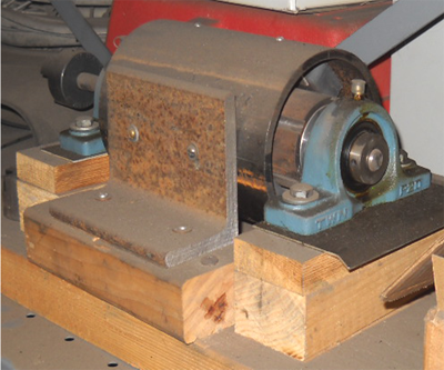 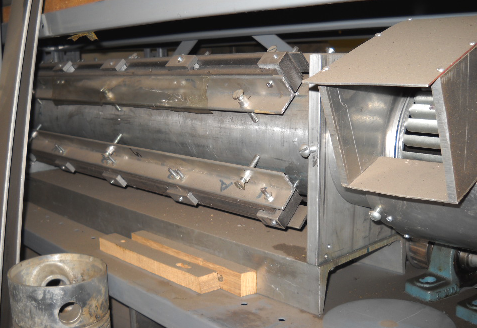 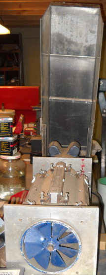 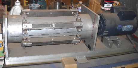 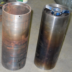 These pictures are of a magnetic heater driven by an induction motor. There are magnets placed between steel pole pieces which are adjustable to allow for the expansion caused by heating. The cylinders are made from A53 type steel. Cast iron is not suitable as the motor used spins at 3,600 rpm and cast iron has a different magnetic angle, which, while it causes a lot of resistance when being turned, slowly, does not heat up at the high speed used my me. The steel cylinder needs to be electrically isolated from all of the other working parts of the heater and it needs to be allowed to float on the shaft so that it can increase in length as it heats up. The speed of rotation was 3,600 rpm and the cylinder was cut to a wall thickness of 0.108 inch (2.75 mm). The colour distortion on the cylinders shown in the last photograph was caused by the heating of the cylinder when in use. These cylinders reached about 850oF and with the volume of air blown through the cylinder it produced air exhaust temperatures of 148oF. importantly, this exiting air was ionized which provided benefits in addition to heating. Technically speaking, this ionization is actually an inefficiency. When performing magnetic heating, the magnetic field needs to go through the metal and not along itТs surface as is the case in the heater shown above. Because of this, a different style of heater was built as shown here: 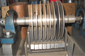 With this design, the magnets should not cover more than one quarter of the disc face and the magnetic field must pass all the way through each disc. Even with air being blown between the discs, the magnets get so hot that it becomes a long-term problem in that magnets lose their magnetism if raised to too high a temperature. The disc thickness is important. There are some advantages of this type of heating mainly the motor type and power consumption allows for better than normal efficiency but that is not high enough for the construction cost to be recovered and that is why this type of heater is not popular. However, it has the advantage that the ionization of the heated air can suppress virus and bacteria on surfaces. It is important to note that a magnet moving over a plate heats only a small zone and the heated metal is only a narrow area within the magnetic field. The magnetic cylinder heater shown was designed in 1989 by the late Frederick J. Galloway. Four videos have been made specifically for this query, showing the 4-kilowatt input power cylinder heater here: Part 1 of 4 Part 2 of 4 Part 3 of 4 Part 4 of 4 Question: What drawing package do you use to produce the diagrams in your eBook? Answer: I use the УPaintФ program which comes free with Windows. As that answer upsets people, I have produced three casual videos explaining how easy it is to use. As I donТt have a video camera or a phone with video facilities, these videos were produced using the FoxMagic program УScreen VirtuosoФ: Video 1 Video 2 Video 3 Patrick Kelly http://www.free-energy-info.tuks.nl |