|
Note: If you are not at all familiar with basic electronics, you might find it easier to follow parts of this chapter if you read chapter 12 first
Heaters The devices described here are probably not “free-energy” devices as such, but in spite of that, it is an area of considerable interest to many people, and the subject is included here because of that. If you do not live in an urban area, then a solid fuel stove can be an economic solution, especially if the fuel can be collected free from wooded areas. Stove design has advanced considerably and it is now possible to make a simple stove with very high efficiency and very low emissions as shown here:  Although this stove is a very simple construction, it’s efficiency is very high indeed. The best fuel is made of smaller pieces which rest on a simple shelf. Branches work better than large pieces of wood as the consumption is more complete. As the fuel is consumed, it is pushed further into the stove, which gives the user an appreciation of the rate of consumption. Having the fuel resting on a shelf has the major advantage of allowing air to flow both above it and below it, which gives improved combustion. The operation is said to be so good that there is virtually no residue and no emissions. Again, if land space is available, a solar oven (or Stirling motor) can be used, either to store energy for later use or generate heat for cooking or home heating, as can hot-water solar panels. However, it is only realistic to consider the application to be during the night in a built-up area with little or no spare space for equipment. The Wood-gas Stove There is another very effective type of wood-burning stove. There are several commercial versions of this stove on sale, but most of them use an electric fan to get the effect which is produced automatically by this design. This design has been replicated by Alberto Feliciano and found to be very effective in operation. It causes a load of wood which would normally burn up in fifteen minutes to burn for a whole hour, putting out a much greater amount of heat. The design is very straightforward. There is an outer drum which has a solid base, and the opposite end removed entirely as shown here:  A ring of ventilation holes is drilled around the whole of the bottom edge of the drum and threaded rods are run through the drum. These support a circle of wire mesh which forms a supporting shelf. A smaller drum then has both ends removed, to form a cylinder. This cylinder is to fit inside the outer drum. It rests on the mesh shelf of the outer drum. This cylinder has a ring of ventilation holes is drilled around the whole of it’s upper edge as shown here:  A third drum which is only slightly smaller than the outer drum is cut down to make a cap for the inner cylinder. This cap is not tight-fitting, but it effectively closes off the top of the gap between the sides of inner cylinder and the sides of the outer drum:  This cap has a circular hole cut in it, and this hole is only slightly smaller than the diameter of the inner cylinder. It is supported by the upper lip of the inner drum but the hole is large enough that it does not obstruct the flow of heat up through the top of the inner drum. These three pieces fit together like this:  Wood of any type, branches, sticks, firewood, etc. are placed inside the inner cylinder and set alight. Initially, the flames come out of the top of the stove as you would expect, but after a few minutes, the combustion alters completely. The burn now becomes that of wood-gas rather than of the wood itself. The wood is slowly converted to charcoal and the gas released by this process burns with greater heat than the wood would give as well as burning for a much greater length of time. This stove design can be made in any size. Small versions get a burn length of about three times that of the wood burning in the open air, while large versions can reach four times the burn length. Flames no longer come out of the top of the stove, but instead, they come out of the ring of holes around the base of the outer drum. The process is like this:  A high-temperature gas burn takes place in the centre of the inner cylinder. This pushes heat out through the top and the bottom of the inner cylinder. The heat flowing out of the top is used for heating or cooking as before. The heat flowing out of the bottom gets diverted around the outside of the inner drum, flows upwards, is caught by the cap and fed back into the inner cylinder through the ring of holes at the top of the inner cylinder. This raises the temperature of the gas burn even further and it augments the heat coming out of the top of the stove. The result is a very hot burn which goes on far longer than would happen if the same wood was burnt on an open fire or in a single open drum. When the wood reaches the end of it’s burn cycle, it can be replaced by feeding new wood through the hole in the cap which rests on the inner cylinder. The stove will need to be emptied of ash from time to time. Mr Teslonian’s Heating / Fuel-producing / Electricity and Refrigeration System The Wood-gas stove shown above has been taken several steps further by “Mr Teslonian” as shown in his videos: here and here where he burns twigs in a home-made wood-gas furnace, heats his house, heats his water, produces engine fuel, runs an electricity generator off the gas and powers a refrigerator. All that, from a few twigs! This is very impressive and he is definitely to be congratulated for his development. His basic wood-gas stove can produce flames up to eight feet (2.5m) tall when operating very effectively on just a few handfuls of short twigs and branches. It looks like this: 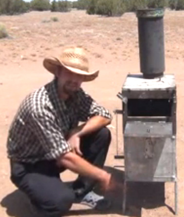 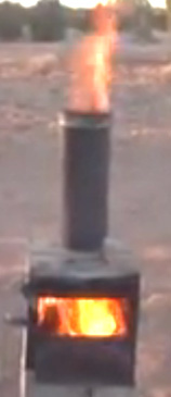 This very effective wood burner produces enough heat to heat a house and produce hot water. The wood-gas can also be used to produce both crude oil and fairly well-refined oil which can be used in an engine: 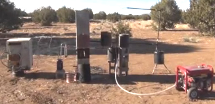 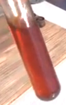 And as you can see from the picture above, the wood-gas can run an electricity generator. There is a world of difference between burning wood like this and a typical camp fire or bonfire. Wood-gas can also be used to run vehicles (as was done during World War 2). Links to a great deal more information include: www.woodgas.net - an enthusiasts site with basic explanations and many links. construction plans for any full size engine. using wood-gas in a vehicle. wood-gas as engine fuel. generator for charging battery banks. small scale biomass gasifiers for heat and power the best oils to use with wood-gas engines Solid Fuel Producing Electricity We then to think of small-scale solid-fuel burners as providing heat and perhaps a little light as well. The peopole in Siberia don’t think like that and they produce a range of (just) portable solid fuel stoves which provide heating, cooking and 12-volt electricity up to 50 watts. While 50 watts doesn’t sound like much, it is a major amount when there isn’t any at all available. A small inverter provides mains AC power for smaller appliances: 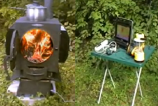 If it is still there, the video of this is here and the manufacturers here show a video of this stove design being used in a snow-covered wood at -32 Centigrade temperatures, giving about +35 degrees Centigrade inside the tent. Mind you, weighing in at 54 kilograms which is a whopping 120 pounds or so, this is not a back-packing solution for camping trips. Sales outlets are in Siberia, New York, Australia, Kyrgyzstan, Ukraine, Belarus, Kazakhstan and Latvia at the present time. The HHO Gas Option Electrical heating, while very convenient, is usually expensive, and it often seems that the effectiveness of an electric heater is not directly related to its power consumption. In theory it definitely is, but in practice it just does not seem that way. There are other alternatives. One of the other documents in this set, shows how to construct a Stanley Meyer style electrolyser which uses ordinary tap water and splits it into burnable fuel using just a low power electrical input: 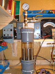 The difficulty in creating a heating system which uses the gas produced by this unit, is in the very high temperature produced when the gas is burnt. Stan overcame this problem with by designing a special burner which mixes air and burnt gasses in with the gas before it is burnt. That lowers the flame temperature to a level which is suitable for heating and cooking:  While this looks a bit complicated, it’s construction is really quite simple. The combination of the Meyer electrolyser and Meyer burner form a system which has the potential of being operated from a solar panel and battery as shown here:  A system like this needs extreme care as the hydrogen / oxygen (“HHO”) gas produced is explosive. So:
 The idea is to bubble the HHO gas produced by electrolysis of water, through a liquid hydrocarbon such as turpentine or acetone. The bubbler should have a large number of small holes in the incoming tube, so that a very large number of small bubbles of HHO gas pass through the hydrocarbon. This brings the majority of the HHO gas into intimate contact with the hydrocarbon and the process is claimed to convert the HHO gas into a new variety of gas which is not explosive, can be stored for later use, and which burns with the same characteristics as coal-gas (“town gas”). David Quirey has used this method very successfully for more than twenty years now (details in chapter 10). Sang Nam Kim. Mr Kim of Korea also proposes methods of using hydroxy gas for heating and using Henry Paine's hydrocarbon bubbling method. He has four patents on the subject of heating: US 6,397,834 in June 2002 - Heating Furnace US 6,443,725 in September 2002 - Energy Generatin US 6,761,558 in July 2004 - Heating Apparatus US 7,014,740 in March 2006 - Electrolyser The first of these shows his method of getting both beneficial radiant heat and convention heating from a stone construction like this:  This unit is intended as a seriously powerful heating source for a minimum of one room. Mr Kim quotes a hydroxy gas requirement of 30 litres per minute which is a very considerable amount, and if the gas is produced by electrolysis of water at Faraday efficiency, it would need a current draw of 4.2 kilowatts. There is every indication that Mr Kim's method of electrolysis is low efficiency as his latest patent shows a radiator and fan:  Mr Kim also shows a burner intended for use with an existing furnace. He remarks that the outer casing gets to be red hot, running at 1,000oC or more, and so any replication of his design should be treated with care when mounting fixtures are being constructed. In this design, Mr Kim uses the Paine technique and recommends bubbling his hydroxy gas through hexane liquid (C6H14) where 0.3 litres of hexane per hour gets burnt as well as the hydroxy gas. He rates the hydroxy gas requirement of this burner as being 20 lpm, which at Faraday efficiencies, represents 2.8 kilowatts of electricity, although as mentioned before, it is likely that the actual amount of hydroxy gas in his 20 lpm volume is much lower than he thinks, and so will have a lower electrical requirement when using a more electrically efficient electrolyser. His burner is like this:  Mr Kim believes that the hexane prevents flashback ignition. He does not appear to specify the heating material inside the burner but it is probably stainless steel wool. He speaks of gas pressures of 1 Kg per sq. cm., which, if my calculations are correct is 14.22 psi. which is not possible for 100% hydroxy gas as it will explode spontaneously at 12 psi. due to its high energy state and electrical charge. He states that the secondary flames at the top of the unit "burn with a blue flame colour" and that is different to the flame colour lower down. Mr Kim believes that the hydroxy burnt at the bottom of the burner forms water vapour which is then split into hydroxy gas again by the very high temperature and that is the reason for the blue flames at the top. Personally, I don't believe that this will take place and that the effect may have a good deal to do with the hexane liquid being burnt. However, this burner design appears to be a good one for lower grades of hydroxy gas. If a higher grade of hydroxy gas is being used, please be aware that a hypodermic-size tiny burner orifice will be needed to avoid flashbacks and no commercial flashback arrester will work reliably with good quality hydroxy gas on every occasion and so a bubbler is absolutely essential. The Hydrogen Garage In 2013, Andrew of the Hydrogen Garage in America stated: We are heating up the shop with only 216 watts, 12 Volts at 18 amps using one “dual 7 plate” electrolyser cell with a water tank and bubbler and a 5-inch dryer, hose and torch which can be operated continuously 24/7 if desired. The flames produced are pointed into a central stainless steel tube 12-inches (300 mm) long and 1-inch (25 mm) in diameter. Wrapped all around the central pipe are 10 more stainless steel tubes held together as a group by 2 hose clamps. The set of pipes is placed on the concrete floor. In our work, we have to prepare HHO electrolyser cells and the HHO gas produced during that process is used to heat the shop. No more need for propane and no more headaches from 6 hours of heating the room. Now the HHO gas adds ozone to the air in the shop and there are no fumes and no smell. The burner used is shown here and it can be powered by one 14/7 HHO cell available here There is no need for a Pulse-Width Modulator unit as you can just use direct DC power from a DC power supply or battery charger. Solar panels can run HHO cells well. 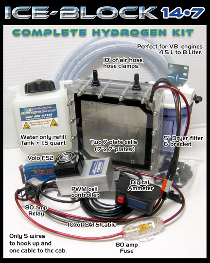 Catalytic HHO Heating from Justin Church On Sterling Allan’s website at http://peswiki.com there is a description of an HHO heating process which has been under development since 2010. It is a particularly interesting system in that no flame is involved, but instead, a stream of HHO gas is fed into a standard vehicle catalytic converter along with air which can freely enter the converter. Justin has found that with a quite low flow of HHO, such as that produced by 13.8V at 5A (70 watts), the converter heats up to a level which can barely be touched and that is quite remarkable considering that the converter is has substantial weight of metal in its construction. Measurements of the temperature inside the converter show that it is running at more than five hundred degrees F. Justin calls his unit the “H-Cat”:  Sterling’s web site is definitely worth a visit. Electric power is very popular for heaters. However, with most appliances, it is a very expensive form of heating. There is a technique which is reputed to improve the efficiency and lower the cost of electric heating. This method involves rotating a cylinder inside an outer cylinder and filling part of the narrow space between the cylinders with some variety of light oil. This method has been patented more than once. In 1979, Eugene Frenette was granted patent 4,143,639 where a single motor is used to rotate the drum and power a fan to boost the motion of the hot air:  It is not immediately obvious why this arrangement should work well, but it appears that it does. As the inner drum spins around, the oil rises up between the two inner cylinders. It lubricates the bearing under the rotating drum and the rotation causes the oil to heat up. This heats the middle cylinder and air being drawn up around it by the action of the fan blade, is also heated before being pushed out of the top of the heater. After a few minutes, the outer housing becomes so hot that the thermostat attached to it, cuts off the electrical supply. The heater does not stop heating at this time as air continues to circulate through the heater by ordinary convection. In my opinion, it would be more effective if the fan motor were operated independently and did not cut off when the heater reaches its operating temperature. Very similar systems were patented by Eugene Perkins: January 1984 patent 4,424,797, November 1984 patent 4,483,277, March 1987 patent 4,651,681, October 1988 patent 4,779,575, and in January 1989 patent 4,798,176. His first patent shows a horizontal drum which is completely immersed in the liquid:  This calls for a much greater accuracy of construction in that the liquid has to be contained even though it has a rotating shaft running through the housing. This device pumps the heated liquid through central-heating piping and radiators. In his later patent of the same year, he shows a modified version with two drums and an impeller:  The “heat exchanger” is a radiator or set of radiators. He progressed to a system where the shaft rotation forces the liquid to be expelled through the tips of arms radiating out from the centre of the impeller hub:  Here, the liquid is forced into a small space between the rotor and its drum housing. This system has been used very successfully for water heating and some measurements indicate that it is at least 100% efficient and some people believe that it is well over the 100% efficiency, though they don’t want get drawn into long discussions on methods of measurement. It is sufficient to say here, that this method is very effective indeed. Frenette Variation: The Frenette heater design shown above with it’s two vertical cylinders, is not the easiest for the home constructor unless one of the cylinders (presumably the inner one) is constructed from steel sheet, as it is difficult to find two commercially available steel cylinders of just the right relative size to produce the wanted gap between them. A much easier variation replaces the inner cylinder with a stack of circular steel discs. As these can be cut from 20 gauge steel sheet fairly readily by the home constructor, or alternatively, cut by any local metalworking or fabrication company, any available size of outer cylinder can be used and the disc diameter chosen accordingly. The discs are mounted about 6 mm (1/4”) apart on a central steel rod which is rotated in order to drive the discs through the oil contained inside the body of the heater. While this looks like a Tesla Turbine, it is not because the spacing of the discs creates a different effect. The wider disc spacing creates shear as they spin through the surrounding oil, and this shearing creates a high degree of heating. It must be remembered that this is a heater, and the outer canister gets very hot during operation (which is the whole point of the exercise in the first place). For that reason, oil is used as a filling and not water, which boils at a much lower temperature. The larger the diameter of the canister and the greater the number of discs inside it, the greater the heat developed. To ensure that the discs do not come loose during prolonged operation, a hole can be drilled through them just outside the area covered by the locking/spacing nuts, and a stiff wire run through the holes and the ends either welded to the central rod or pushed through a hole drilled in it and bent over to hold it in place. The heat of the cylinder can be circulated by attaching a simple fan blade to the spinning shaft. This blows air down the hot sides of the canister, moving it towards the floor which is the most effective place for it circulate and heat the entire room. As the discs spin, the oil is pushed outwards and moves upwards, filling the top of the canister and building up some pressure there. This pressure can be relieved by running an external pipe from the top of the cylinder back to the bottom, allowing the oil to circulate freely. This has the decided advantage the circulating oil can be passed through a radiator as shown in the following diagram:  The central rod can be rotated by any convenient motor, conventional, Adams type, pulse-motor, permanent magnet motor, or whatever. An alternative to this style of operation, is to use the rotating motor to spin a ring of permanent magnets positioned close beside a thick aluminium plate. The eddy currents cause very strong heating of the aluminium plate which then can have air blown across it to provide space heating. The Peter Davey Heater. During World War II, Peter Daysh Davey, of Christchurch, New Zealand, a fighter pilot and musician, designed and built an unusual water heater. This design is not particularly well known and information is fairly thin on the ground, however, the basic principle and design details are known.  The device is intended to operate on the New Zealand mains power supply of 220 volts 50 Hz and a requirement of the apparatus is that it resonates at that 50Hz frequency. Resonance is a frequent requirement of free-energy systems, and the need for it is often overlooked by people who attempt to replicate free-energy devices. Properly built and tuned, this heater is said to have a COP of 20, which means that twenty times as much heat is produced by the device, compared to the amount of electrical power required to make it operate. This power gain is caused by additional energy being drawn from the immediate environment and it is very important as the largest use of energy in cool climates tends to be that used for heating. If that can be reduced by a serious amount, then your annual power costs should be much lower as a result of it. Peter was granted a New Zealand patent for his heater on 12th December 1944 but he found that after the war, the opposition from the utility companies was so great that it prevented him from going into commercial production with it. For fifty years, Peter kept up his attempts to get sufficient approval to bring his heater to the marketplace, but the opposition finally won and he never managed it. The device comprises a hemispherical resonant cavity, formed from two metallic dome shapes, both of which resonate at 50Hz. Initially, Peter used two bicycle bells and he found that when submerged in water, the device brought the water to the boil in a very short time indeed. The construction is like this:  If construction were to use two identical hemispheres, then the cavity between them would be anything but even width throughout, but the resonance would be the same. On the other hand, if you want the resonant cavity between the two hemispheres to be of constant width, then the outer sphere needs to be markedly larger than the inner hemisphere. The outside of both hemispheres needs to be insulated unless mounted in such a way that it is not possible to touch the hemispheres, as each is attached to the mains. In the above diagram, the mains live wire 6, is fed through the connecting pipe 8, and clamped to the inside of the inner hemisphere 1, by nut 3 which screws on to the threaded section of tube 8. It is important that it is the live wire which is connected to hemisphere 1. The mains neutral wire 7, is also fed through the connecting tube 8, exits via a small hole and is clamped on to the outside of the outer hemisphere 2, by nut 5, also on the threaded section of tube 8. The two hemispheres are held apart by a spacing washer 4, which is made from a high-temperature non-conducting plastic. As the tube 8 connects electrically and mechanically to both mains wires via the two locking nuts 3 and 5, it is essential that this tube is constructed from an electrically non-conducting material such as plastic. As the tube will be in boiling water on a regular basis, it is also necessary that the tube material is also able to handle temperatures over 100o C (212o F), so possible materials include nylon and teflon. This washer is a key component of the heater and its thickness is key to the efficiency of the whole device. This thickness L, is the tuning control for the cavity. The outer hemisphere is about 8 mm greater in diameter than the diameter of the inner hemisphere. Allowing for the thickness of the metal of the bowl, the resonant cavity will therefore be about 3 mm or one eighth of an inch. The hemisphere 1 is also tuned to 50 Hz by grinding it carefully until it resonates freely at that frequency. Connecting a loudspeaker in series with a resistor of say, 100K ohms, will give a sound of the exact frequency with which this hemisphere needs to resonate. This tuning needs to be done with the unit fully assembled as the connections to the tube will alter the resonant frequency of the hemisphere. When this is being done, the resonance will be felt rather than heard, so hold the tube lightly so that it can resonate freely. The tuning is done by removing a small amount of metal from the face of hemisphere 1 and then testing for resonance again. When hemisphere 1 resonates well at the mains frequency, (roughly G two octaves below middle C on a keyboard), the search for high-efficiency heating is carried out by very small adjustments of the gap L. The adjustment of the gap L is carried out by very careful grinding down of the separating washer 4 and the result is best determined by measuring the length of time needed to boil a known volume of water and the current taken to do that. Repeated tests and recorded results, shows when the best gap has been reached and the highest efficiency achieved. The heater can, of course, be used to heat any liquid, not just water. This heater is unlike a standard kettle heating element. In the standard method, the water is not a part of the main current-carrying circuit. Instead, the mains power is applied to the heater element and the current flowing through the heater element causes it to heat up, and the heat is then conveyed to the water by conduction. In Davey’s heater, on the other hand, the current flow appears to be through the water between the two hemispheres. It seems likely that the actual heating is not produced by current flow at all, but from cavitation of the water caused by the resonating of the cavity between the two hemispheres. This technique is used in small jewelry cleaners where and audio frequency is applied to a cleaning fluid in a small container. A small amount of electrolysis will take place with the Davey heater as it in effect also forms a single parallel-connected electrolyser. The amounts should be very small as only 1.24 volts out of the 220 volts applied will be used in the electrolysis process. An early construction of the original heater is shown in the photograph below. The coin shown in the picture is 32 mm (1.25 inch) in diameter. The heater is submerged in water when it is being used, and it brings that water to the boil exceptionally quickly. The unit was tested by New Zealand scientists who were able to vouch for its performance, but who were unable to state exactly how its operation allowed it to output such a high level of heat for such a low level of electrical input. You will notice from the photograph, how carefully the electrical connections and outer bowl are insulated. 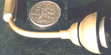 The original prototype which Peter made was constructed from the tops of two bicycle bells, only one of which was tuned to 50 Hz. This shows that the device will definitely work if the inner hemisphere is tuned correctly. You can find forum investigation here and more recent information here. Jean-Christophe Dumas A Frenchman, Jean-Christophe Dumas, publicises his COP=1.17 heater design which appears to operate in a very similar way to that of Peter Davey. His website is here and it gives an English translation of much of what he has to say. In this design, steam is produced almost immediately after some 500 watts of input power is applied. He uses a metal sphere plus one metal hemisphere which has an adjustable spacing over half of the sphere’s surface. Jean-Christophe wishes to share his design freely with everybody and he sees it as being used for efficient space heating in houses, given a radiator system. His drawings are:     The Series-connected Heater. While not a free-energy device, one simple arrangement which I use myself, is an adapted halogen heater. A standard, low-cost halogen heater consists of three separate 400-watt sections with a switching arrangement which allows one, two or three sections to be powered up:  I changed the connections inside my particular heater, so that all three halogen lamps are connected in a chain. This did not involve cutting any wires or making any new connections as the wires connecting to the lamps have push-on ‘spade’ connectors to allow for both simple manufacturing and easy replacement of a halogen lamp. The new arrangement is like this:  This arrangement ‘under-runs’ the lamps as each lamp only gets one third of the voltage which it was designed for. This has the effect of increasing the working life of the lamp enormously. You would expect the heat output to be very poor, and perhaps it is. But it gives the impression of being quite effective and with all of the three sections working, it provides a gentle heat and light which seems very effective in keeping a room warm. The Home Power, Home-Build Wind-Powered Electrical Generator Here is an interesting article from the Home Power web site. If you are interested in renewable power, then I strongly recommend that you visit their web site and consider subscribing to their magazine as they cover many practical topics using simple wording. Here is an example of the high quality material from Home Power – a 100 watt wind generator built from scratch in just one day:  The link for this is: here. William McDavid junior remarks that a horizontal axis windmill of that type creates an area of slow-moving air behind the blades and that restricts the flow of air past the blades. A way to overcome that is to project the outgoing air in a direction which does not impede the incoming air. He shows how this can be done in his patent US Patent 6,800,955 of 5th October 2004. In this design, the wind blows into the generator housing and is deflected upwards through the fan blades of a turbine which spins an electrical generator:  One clever feature common to both of these designs is the use of a stationary circular housing with deflectors which uses the wind flow no matter what the wind direction happens to be at any given moment. Looking down from above, the housing looks like this:  This view shows two important features which enhance the performance of the device. The first is that hinged flaps allow the (horizontal) inflow of air but block the air from flowing straight out of the other side of the central section. This forces the wind to turn and flow upwards, and not only that, but this arrangement causes the air to spin, creating a miniature tornado vortex which amplifies the power of the wind as can be seen from the devastation caused by full-size tornadoes in the environment. As can be seen from the upper diagram, an upward-curving conical piece on the base of the housing assists the airflow to turn upwards as it spins. The spinning air helps to spin the generator blades faster, giving additional power. A major additional feature is the fact that the dimension “A” is considerably less than the dimension “B” due to the reduced diameter of the housing nearer the centre. This means that the air flowing past the vanes of housing gets squeezed into a smaller space as it flows. This forces the air to speed up, causing the flow inside the central housing to be higher than the wind-speed outside and that boosts the performance of the device. This wind-powered generator looks like a straightforward project for home construction and with the air being deflected vertically, there does not appear to be any reason why several should not be located near each other. William’s full patent can be seen in the appendix of this eBook, or as a separate Patent on this website. Frank Herbert’s Windmill. As has been carefully explained by the above article, if a windmill of the blade variety is mounted low down then it is dangerous, and people on sailing boats have been killed by them. Also, if the blade arrangement is designed to operate well in low wind conditions, then it is not unusual for there to be a problem if the wind rises to gale force or higher, with some generator designs giving up and switching off entirely, even though the available free energy is at its highest level. This design by Frank Herbert is perfectly capable of being home-built and yet it overcomes these problems as well as being a high-efficiency wind turbine. It has an outside cage which prevents human access to the moving parts inside and the ‘cage’ is not just for protection but is there to enhance the performance of the device. In passing, windmills can be used to compress air and compressed air cylinders can be used to power vehicles and/or power electrical generators during periods of heavy power requirements. The following information is from Frank Herbert’s US Patent 4,142,822 of 1979:  The vertical housing 22 shown dotted here, surrounds the vertical power take-off shaft 26. The wind is allowed to flow through this housing at any angle, so there is no need for the housing to move. In the diagram above small discs 44 are shown at each end of the vertical shaft. These discs have arms 42 extending outwards to support a series of vertical vanes or pressure surfaces 24. For clarity, just one vane is shown through there will actually be many of these (rather like the cutting blades on a cylinder lawnmower). In reality, there will be no arms on the discs 42 as it is much easier just to have a full-width solid disc supporting the vanes. The outer housing has a series of vertical slats which are angled to direct the incoming wind on to the vanes at the best possible angle:  This top view of part of the device, shows the main mounting shaft 26 on which the top and bottom rotor discs are mounted. The red dots show the pivot points where the vanes 24 can turn to take the greatest advantage of the wind pressure. The incoming wind 36, is deflected by the slats of the housing 32, to give it a good angle when flowing through the device as well as keeping humans away from the spinning mechanism. As the vanes and slats are located all the way around shaft 26, sudden changes in wind direction and/or wind strength have no particular effect on this design as it operates with wind coming from any direction and no physical movement of any part of the device is needed for a change in wind direction. The vanes can have various different profiles and still work well. The shape shown above is the shape of an aircraft wing, where a force acting towards the curved surface is generated when air flows around the shape. This is not a particularly difficult shape to construct and it is very effective in an airflow (which is why it is used to lift aircraft off the ground). There can be any convenient number of vanes and a device built as shown above should be very effective.. As the overall efficiency is improved if there is no turbulence inside the device, Frank has found a method of minimising this. For this, he uses a mechanism which can alter the shape of the vanes when the windspeed gets high. The higher windspeed whirls the vanes around faster, causing higher ‘centrifugal’ forces on the vanes which Frank uses as follows. Weight 54 gets pushed across by the spin rate of the rotor.  This pushes against the spring 56, compressing it. The triangle link 59 moves upwards, pivoting at points 59a and 59c, and raising section 50 of the vane. This changes the shape of the vane as shown here:  The result of this changed shape is to reduce turbulence inside the device and raise the overall efficiency. Mead and Holmes. The US patent 4,229,661 dated 1980 from Claude Mead and William Holmes is entitled “Power Plant for Camping Trailer” proposes the use of a wind power generator to store compressed air for later use in providing household electrical current, and simultaneously charge batteries which can be used to drive the compressor in periods of very high electrical demand. There is also an option for a rapid system charge if AC mains power becomes available:  Solar Ovens. This information comes from http://solarcooking.org/plans/funnel.htm and ownership remains with the original authors and this material is reproduced here with their kind permission. How to Make and Use The Brigham Young University Solar Cooker/Cooler by Professor of Physics at Brigham Young University (BYU), with Colter Paulson, Jason Chesley, Jacob Fugal, Derek Hullinger, Jamie Winterton, Jeannette Lawler, and Seth, David, Nathan, and Danelle Jones. 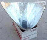 Introduction A few years ago, I woke up to the fact that half of the people in the world must burn wood or dried dung in order to cook their food. It came as quite a shock to me, especially as I learned of the illnesses caused by breathing smoke day in and day out, and the environmental impacts of deforestation - not to mention the time spent by people (mostly women) gathering sticks and dung to cook their food. And yet, many of these billions of people live near the equator, where sunshine is abundant and free. So..... As a University Professor of Physics with a background in energy usage, I set out to develop a means of cooking food and sterilising water using the energy freely available from the sun. First, I looked at existing methods. The parabolic cooker involves a reflective dish which concentrates sunlight to a point where the food is cooked. This approach is very dangerous since the sun's energy is focused to a point which is very hot, but which cannot be seen. (Brigham Young University students and I built one which will set paper on fire in about 3 seconds!). I learned that an altruistic group had offered reflecting parabolas to the people living at the Altiplano in Bolivia. But more than once these parabolas had been stored next to a shed -- and the passing sun set the sheds on fire! The people did not want these dangerous, expensive devices, even though the Altiplano region has been stripped of fuel wood. The box cooker is basically an insulated box with a glass or plastic lid, often with a reflecting lid to direct sunlight into the box. Light enters through the top glass (or plastic), to slowly heat up the box. The problems with this design are that energy enters only through the top, while heat is escaping through all of the other sides, which have a tendency to draw heat away from the food. When the box is opened to put food in or take it out, some of the heat escapes and is lost. Also, effective box cookers tend to be more complicated to build than the funnel cooker. While studying this problem, I thought again and again of the great need for a safe, inexpensive yet effective solar cooker. It finally came to me at Christmastime a few years ago, a sort of hybrid between the parabola and the box cooker. It looks like a large, deep funnel, and incorporates what I believe are the best features of both the parabolic cooker and the box cooker. The first reflector was made at my home out of aluminium foil glued on to cardboard, then this was curved to form a reflective funnel. My children and I figured out a way to make a large cardboard funnel easily. (I'll tell you exactly how to do this later on.) The Solar Funnel cooker is safe and low cost, easy to make, yet very effective in capturing the sun's energy for cooking and pasteurising water -> Eureka! Later, I did extensive tests with students (including reflectivity tests) and found that aluminised Mylar was good too, but relatively expensive and rather hard to come by in large sheets. Besides, cardboard is found throughout the world and is inexpensive, and aluminium foil is also easy to come by. Also, individuals can make their own solar cookers easily, or start a cottage-industry to manufacture them for others. Prototypes of the Solar Funnel Cooker were tested in Bolivia, and outperformed an expensive solar box cooker and a “Solar Coolkit” while costing much less then either. Brigham Young University submitted a patent application, mainly to insure that no company would prevent wide distribution of the Solar Funnel Cooker. Brigham Young University makes no profit from the invention. (I later learned that a few people had had a similar idea, but with methods differing from those developed and shown here). So now I'm trying to get the word out so that the invention can be used to capture the free energy coming from the sun - for camping and for emergencies, yes, but also for every day cooking where electricity is not available and where even fuel wood is getting scarce. How it Works The reflector is shaped like a giant funnel, and lined with aluminium foil. (Easy to follow instructions will be given soon). This funnel is rather like the parabolic cooker, except that the sunlight is concentrated along a line (not a point) at the bottom of the funnel. You can put your hand up the bottom of the funnel and feel the sun's heat, but it will not burn you. Next, we paint a jar black on the outside, to collect heat, and place this at the bottom of the funnel. Or a black pot with a lid can be used. The black vessel gets hot, quickly, but not quite hot enough to cook with. We need some way to build up the heat without letting the outside air cool it. So, I put a cheap plastic bag around the jar -- and, the solar funnel cooker was born! The plastic bag, available in grocery stores as a "poultry bag", replaces the cumbersome and expensive box and glass lid of solar box ovens. You can use the plastic bags used in American stores to put groceries in, as long as they let a lot of sunlight pass. (Dark- coloured bags will not do). I recently tested a bag used for fruits and vegetables, nearly transparent and available free at American grocery stores, that works great. This is stamped "HDPE" for high-density polyethylene on the bag (ordinary polyethylene melts too easily). A block of wood is placed under the jar to help hold the heat in. (Any insulator, such as a hot pad or rope or even sticks, will also work). A friend of mine who is also a Physics Professor did not believe I could actually boil water with the thing. So I showed him that with this new "solar funnel cooker" I was able to boil water in Utah in the middle of winter! I laid the funnel on its side since it was winter and pointed a large funnel towards the sun to the south. I also had to suspend the black cooking vessel -- rather than placing it on a wooden block. This allows the weaker sun rays to strike the entire surface of the vessel. Of course, the Solar Funnel works much better outside of winter days, that is, when the UV index is 7 or greater. Most other solar cookers will not cook in the winter in northern areas (or south of about 35 degrees, either). I thought that a pressure cooker would be great. But the prices in stores were way too high for me. Wait, how about a canning jar? These little beauties are designed to relieve pressure through the lid -- a nice pressure cooker. And cooking time is cut in half for each 10ºC we raise the temperature (Professor Lee Hansen, private communication). I used one of my wife's wide-mouth canning jars, spray-painted (flat) black on the outside, and it worked great. Food cooks faster when you use a simple canning jar as a pressure cooker. However, you can also put a black pot in the plastic bag instead if you want. But don't use a sealed container with no pressure release like a mayonnaise jar -- it can break as the steam builds up (I've done it)! How to Build Your Own Solar Funnel Cooker What You will Need:
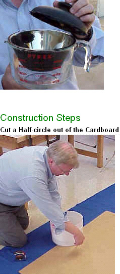 Cut a half circle out of the cardboard, along the bottom as shown below. When the funnel is formed, this becomes a full-circle and should be wide enough to go around your cooking pot. So for a 7" diameter cooking pot, the radius of the half-circle is 7". For a quart canning jar such as I use, I cut a 5" radius half-circle out of the cardboard. 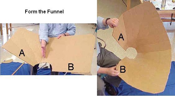 To form the funnel, you will bring side A towards side B, as shown in the figure. The aluminium foil must go on the INSIDE of the funnel. Do this slowly, helping the cardboard to the shape of a funnel by using one hand to form creases that radiate out from the half-circle. Work your way around the funnel, bending it in stages to form the funnel shape, until the two sides overlap and the half-circle forms a complete circle. The aluminium foil will go on the INSIDE of funnel. Open the funnel and lay it flat, "inside up", in preparation for the next step. Glue Foil to Cardboard 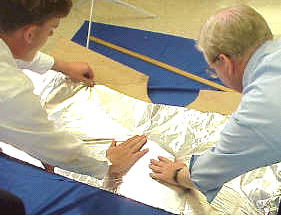 Apply glue or adhesive to the top (inner) surface of the cardboard, then quickly apply the aluminium foil on top of the glue, to affix the foil to the cardboard. Make sure the shiniest side of the foil is on top, since this becomes your reflective surface in the Funnel. I like to put just enough glue for one width of foil, so that the glue stays moist while the foil is applied. I also overlap strips of foil by about 1" ( or 2 cm). Try to smooth out the aluminium foil as much as you reasonably can, but small wrinkles won't make much difference. If cardboard is not available, one can simply dig a funnel-shaped hole in the ground and line it with a reflector, to make a fixed solar cooker for use at mid-day. Join side A to side B to keep the funnel together. 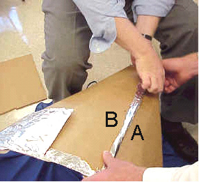 The easiest way to do this is to punch three holes in the cardboard that line up on side A and side B (see figure). Then put a metal brad through each hole and fasten by pulling apart the metal tines. Or you can use a nut-and-bolt to secure the two sides (A & B) together. Be creative here with what you have available. For example, by putting two holes about a thumb-width apart, you can put a string, twine, small rope, wire or twist-tie in one hole and out the other, and tie together. When A and B are connected together, you will have a "funnel with two wings". The wings could be cut off, but these help to gather more sunlight, so I leave them on. Tape or glue a piece of aluminium foil across the hole at the bottom of the funnel, with shiny side in. This completes assembly of your solar funnel cooker. For stability, place the funnel inside a cardboard or other box to provide support. For long-term applications, one may wish to dig a hole in the ground to hold the Funnel against strong winds. Final Steps At this stage, you are ready to put food items or water into the cooking vessel or jar, and put the lid on securely. (See instructions on food cooking times, to follow). Place a wooden block in the INSIDE bottom of the cooking bag. I use a piece of 2” x 4” board which is cut into a square nominally 4" x 4" by 2" thick. Then place the cooking vessel containing the food or water on top of the wooden block, inside the bag. Next, gather the top of the bag in your fingers and blow air into the bag, to inflate it. This will form a small "greenhouse" around the cooking vessel, to trap much of the heat inside. Close off the bag with a tight twist tie or wire. Important: the bag should not touch the sides or lid of the cooking vessel. The bag may be called a "convection shield," slowing convection-cooling due to air currents. Place the entire bag and its contents inside the funnel near the bottom as shown in the Photographs. Place the Solar Funnel Cooker so that it Faces the Sun Remember: Sunlight can hurt the eyes: so please wear sunglasses when using a Solar Cooker! The Funnel Cooker is designed so that the hot region is deep down inside the funnel, out of harm's way. 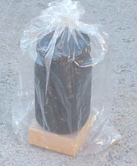 Put the Solar Funnel Cooker in the sun pointing towards the sun, so that it captures as much sunlight as possible. The design of the funnel allows it to collect solar energy for about an hour without needing to be re-positioned. For longer cooking times, readjust the position of the funnel to follow the sun's path. In the Northern Hemisphere, it helps to put the Solar Funnel Cooker in front of a south-facing wall or window as this reflects additional sunlight into the funnel. A reflective wall is most important in locations farther from the equator and in winter. In the Southern Hemisphere, put the Solar Funnel Cooker in front of a North-facing wall or window to reflect additional sunlight into your cooker. After Cooking Remember that the cooking vessel will be very hot: so use cooking pads or gloves when handling it! If you are heating water in a canning jar, you may notice that the water is boiling when the lid is first removed - it gets very hot! Open the plastic cooking bag by removing the twist-tie. Using gloves or a thick cloth, lift the vessel out of the bag and place it on the ground or table. Carefully open the vessel and check the food, to make sure it has finished cooking. Let the hot food cool before eating. Helpful Hints Avoid leaving fingerprints and smudges on the inside surface of the cooker. Keep the inner surface clean and shiny by wiping occasionally with a wet towel. This will keep the Solar Funnel Cooker working at its best. If your funnel gets out-of-round, it can be put back into a circular shape by attaching a rope or string between opposite sides which need to be brought closer together. For long-term applications, a hole in the ground will hold the Funnel Cooker securely against winds. Bring the funnel inside or cover it during rain storms. The lids can be used over and over. We have had some trouble with the rubber on some new canning-jar lids becoming soft and "sticky." "Ball canning lids" do not usually have this problem. Running new lids through very hot water before the first use seems to help. The lids can be used over and over if they are not bent too badly when opened (pry off lid carefully). The jar can be suspended near the bottom of the funnel using fishing line or string (etc.), instead of placing the jar on a block of wood. A plastic bag is placed around the jar with air puffed inside, as usual, to trap the heat. The suspension method allows sunlight to strike all surfaces of the jar, all around, so that heats faster and more evenly. This suspension method is crucial for use in winter months. Adjust the funnel to put as much sunlight onto the cooking jar as possible. Look at the jar to check where the sunlight is hitting, and to be sure the bottom is not in the shadows. For long cooking times (over about an hour), readjust the position of the funnel to follow the sun's path. During winter months, when the sun is low on the horizon (e.g., in North America), it is helpful to lay the funnel on its side, facing the sun. 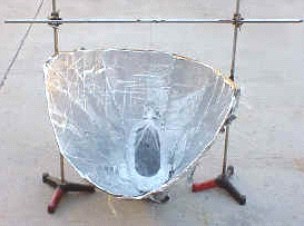 Tests in Utah I have personally used the Solar Funnel Cooker to cook lunches over many weeks. My favourite foods to cook are potatoes (cut into logs or slices) and carrot slices. Vegetables cook slowly in their own juices and taste delicious. I also make rice, melted cheese sandwiches, and even bread in the Solar Funnel Cooker. I usually put the food out around 11:30 and let it cook until 12:45 or 1 pm, just to be sure that it has time to cook. I've never had any food burn in this cooker. I have also cooked food in the mountains, at an altitude of around 8,300 feet. If anything, the food cooked faster there - the sunlight passes through less atmosphere at high altitudes. I find that people are surprised that the sun alone can actually cook food. And they are further pleasantly surprised at the rich flavours in the foods which cook slowly in the sun. This inexpensive device does it! Students at Brigham Young University have performed numerous tests on the Solar Funnel Cooker along with other cookers. We have consistently found much faster cooking using the Solar Funnel Cooker. The efficiency/cost ratio is higher than any other solar cooking device we have found to date. Mr. Hullinger also performed studies of transmissivity, reflectivity and absorptivity of alternate materials which could be used in the Solar Funnel Cooker. While there are better materials, such as solar-selective absorbers, our goal has been to keep the cost of the Solar Cooker as low as possible, while maintaining safety as a first priority. Tests in Bolivia The BYU Benson Institute organised tests between the Solar Funnel Cooker and the "old-fashioned" solar box oven. The solar box oven cost about $70 and was made mostly of cardboard. It took nearly two hours just to reach water pasteurisation temperature. The Bolivian report notes that "food gets cold every time the pots are taken from and into the oven." The solar box oven failed even to cook boiled eggs. (More expensive box cookers would hopefully work better.) 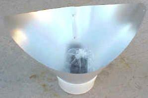 An aluminised-mylar Solar Funnel Cooker was also tested in Bolivia, during the Bolivian winter. Water pasteurisation temperature was reached in 50 minutes, boiled eggs cooked in 70 minutes, and rice cooked in 75 minutes. The Bolivian people were pleased by the performance. So were we! (La Paz, Bolivia, August, 1996). I also donated two dozen solar funnel cookers for people in Guatemala. These were taken there by a group of doctors going there for humanitarian service. The people there also liked the idea of cooking with the sun's free energy. For an aluminised-Mylar Solar Funnel Cooker kit, please contact CRM (licensed manufacturer) at +1 (801) 292-9210. Water and Milk Pasteurisiation Contaminated drinking water or milk kills thousands of people each day, especially children. The World Health Organisation reports that 80% of illnesses in the world are spread through contaminated water. Studies show that heating water to about 65º - 70º C (150º F) is sufficient to kill coliform bacteria, rotaviruses, enteroviruses and even Giardia. This is called pasteurisation. Pasteurisation depends on how hot and how long water is heated. But how do you know if the water got hot enough? You could use a thermometer, but this would add to the cost, of course. When steam leaves the canning jar (with lid on tight) and forms "dew" on the inside of the cooking bag, then the water is probably pasteurised to drink. (The goal is to heat to 160º Fahrenheit for at least six minutes.) With a stripe of black paint scraped off the jar, one can look through the bag and into the jar and see when the water is boiling - then it is safe for sure. Think of all the lives that can be saved simply by pasteurising water using a simple Solar Cooker! Safety Safety was my first concern in designing the Solar Funnel Cooker, then came low cost and effectiveness. But any time you have heat you need to take some precautions.
Cooking with the Solar Funnel Cooker What do you cook in a crock pot or moderate-temperature oven? The same foods will cook about the same in the Solar Funnel Cooker - without burning. The charts below give approximate summer cooking times. The solar cooker works best when the UV index is 7 or higher (Sun high overhead, few clouds). Cooking times are approximate. Increase cooking times for partly-cloudy days, sun not overhead (e.g., wintertime) or for more than about 3 cups of food in the cooking jar. Stirring is not necessary for most foods. Food generally will not burn in the solar cooker. Vegetables (Potatoes, carrots, squash, beets, asparagus, etc.) Preparation: No need to add water if fresh. Cut into slices or "logs" to ensure uniform cooking. Corn will cook fine with or without the cob. Cooking Time: About 1.5 hours Cereals and Grains (Rice, wheat, barley, oats, millet, etc.) Preparation: Mix 2 parts water to every 1 part grain. Amount may vary according to individual taste. Let soak for a few hours for faster cooking. To ensure uniform cooking, shake jar after 50 minutes. CAUTION: Jar will be hot. Use gloves or cooking pads. Cooking Time: 1.5-2 hours Pasta and Dehydrated Soups Preparation: First heat water to near boiling (50-70 minutes). Then add the pasta or soup mix. Stir or shake, and cook 15 additional minutes. Cooking Time: 65-85 minutes Beans Preparation: Let tough or dry beans soak overnight. Place in cooking jar with water. Cooking Time: 2-3 hours Eggs Preparation: No need to add water. Note: If cooked too long, egg whites may darken, but taste remains the same. Cooking Time: 1-1.5 hours, depending on desired yolk firmness. Meats (Chicken, beef, and fish) Preparation: No need to add water. Longer cooking makes the meat more tender. Cooking Times: Chicken: 1.5 hours cut up or 2.5 hours whole; Beef: 1.5 hours cut up or 2.5-3 hours for larger cuts; Fish: 1-1.5 hours Baking Preparation: Times vary based on amount of dough. Cooking Times: Breads: 1-1.5 hours; Biscuits: 1-1.5 hours; Cookies: 1 hour Roasted Nuts (Peanuts, almonds, pumpkin seed, etc.) Preparation: Place in jar. A little vegetable oil may be added if desired. Cooking Time: About 1.5 hours MRE's and pre-packaged foods Preparation: For foods in dark containers, simply place the container in the cooking bag in place of the black cooking jar. Cooking Times: Cooking time varies with the amount of food and darkness of package. How to Use the Solar Funnel as a Refrigerator/Cooler A university student (Jamie Winterton) and I were the first to demonstrate that the Brigham Young University Solar Funnel Cooker can be used - at night - as a refrigerator. Here is how this is done: The Solar Funnel Cooker is set-up just as you would during sun-light hours, with two exceptions:
During the day, the sun's rays are reflected on to the cooking vessel which becomes hot quickly. At night, heat from the vessel is radiated outward, towards empty space, which is very cold indeed (a "heat sink"). As a result, the cooking vessel now becomes a small refrigerator. We routinely achieve cooling of about 20º F (10º C) below ambient air temperature using this remarkably simple scheme. In September 1999, we placed two funnels out in the evening, with double-bagged jars inside. One jar was on a block of wood and the other was suspended in the funnel using fishing line. The temperature that evening (in Provo, Utah) was 78º F (25.5º C). Using a Radio Shack indoor/outdoor thermometer, a BYU student (Colter Paulson) measured the temperature inside the funnel and outside in the open air. He found that the temperature of the air inside the funnel dropped quickly by about 15º F (8º C), as its heat was radiated upwards in the clear sky. That night, the minimum outdoor air temperature measured was 47.5º F (8.6º C) - but the water in both jars had ICE. I invite others to try this, and please let me know if you get ice at 55 or even 60 degrees outside air temperature (minimum at night). A black PVC container may work even better than a black-painted jar, since PVC is a good infrared radiator - these matters are still being studied. I would like to see the "Funnel Refrigerator" tried in desert climates, especially where freezing temperatures are rarely reached. It should be possible in this way to cheaply make ice for Hutus in Rwanda and for aborigines in Australia, without using any electricity or other modern "tricks." We are in effect bringing some of the cold of space to a little corner on earth. Please let me know how this works for you. Conclusion: Why We Need Solar Cookers The BYU Funnel Cooker/Cooler can:
The burden for gathering the fuel wood and cooking falls mainly on women and children. Joseph Kiai reports : From Dadaab, Kenya: "Women who can't afford to buy wood start at 4 am to go collecting and return about noon... They do this twice a week to get fuel for cooking... The rapes are averaging one per week." From Belize: "Many times the women have to go into the forest dragging their small children when they go to look for wood. It is a special hardship for pregnant and nursing mothers to chop and drag trees back to the village... they are exposed to venomous snakes and clouds of mosquitoes." And the forests are dwindling in many areas. Edwin Dobbs noted in Audubon Magazine, Nov. 1992, "The world can choose sunlight or further deforestation, solar cooking or widespread starvation..." Americans should be prepared for emergencies, incident to power failures. A Mormon pioneer noted in her journal: "We were now following in their trail travelling up the Platte River. Timber was sometimes very scarce and hard to get. We managed to do our cooking with what little we could gather up..." (Eliza R. Snow) Now there's someone who needed a light-weight Solar Cooker! Here's another reason to use a solar cooker. Many people in developing countries look to see what's being done in America. I'm told that if Americans are using something, then they will want to try it, too. The more people there are cooking with the sun, the more others will want to join in. A good way to spread this technology is to encourage small local industries or families to make these simple yet reliable solar cookers for others at low cost. I've used this cooker for three summers and I enjoy it. Cooking and making ice with the funnel cooker/cooler will permit a significant change in lifestyle. If you think about it, this could help a lot of people. The BYU Solar Funnel Cooker uses the glorious sunshine -- and the energy of the sun is a free gift from God for all to use! Answers to commonly-asked questions Will the cooker work in winter (in the United States)? As the sun moves closer to the southern horizon in the winter, the solar cooker is naturally less effective. A good measure of the solar intensity is the “UV index” which is often reported with the weather. When the ultraviolet or UV index is 7 or above – common in summer months – the solar cooker works very well. In Salt Lake City in October, the UV index was reported to be 3.5 on a sunny day. We were able to boil water in the Solar Funnel Cooker during this time, but we had to suspend the black jar in the funnel so that sunlight struck all sides. (We ran a fishing line under the screw-on lid, and looped the fishing line over a rod above the funnel. As usual, a plastic bag was placed around the jar, and this was closed at the top to let the fishing line out for suspending the jar.) The solar “minimum” for the northern hemisphere occurs on winter solstice, about December 21st each year. The solar “maximum” occurs six months later, June 21st. Solar cooking works best from about 20th March to 1st October in the north. If people try to cook with the sun for the first time outside of this time window, they should not be discouraged. Try again when the sun is more directly overhead. One may also suspend the jar in the funnel, which will make cooking faster any time of the year. It is interesting to note that most developing countries are located near the equator where the sun is nearly directly overhead all the time. Solar Cookers will then serve year-round, as long as the sun is shining, for these fortunate people. They may be the first to apply fusion energy (of the sun) on a large scale. They may also accomplish this without the expensive infrastructure of electrical power grids that we take for granted in America. How do you cook bread in a jar? I have cooked bread by simply putting dough in the bottom of the jar and placing it in the funnel in the usual way. Rising and baking took place inside the jar in about an hour (during summer). One should put vegetable oil inside the jar before cooking to make removal of the bread easier. I would also suggest that using a 2-quart wide-mouth canning jar instead of a 1-quart jar would make baking a loaf of bread easier. What is the optimum “opening angle” for the funnel cooker? A graduate student at Brigham Young University did a calculus calculation to assess the best shape or opening angle for the Solar Funnel. Jeannette Lawler assumed that the best operation would occur when the sun’s rays bounced no more than once before hitting the cooking jar, while keeping the opening angle as large as possible to admit more sunlight. (Some sunlight is lost each time the light reflects from the shiny surface. If the sunlight misses on the first bounce, it can bounce again and again until being absorbed by the black bottle). She set up an approximate equation for this situation, took the calculus derivative with respect to the opening angle and set the derivative equal to zero. Optimising in this way, she found that the optimum opening angle is about 45 degrees, when the funnel is pointed directly towards the sun. But we don’t want to have to “track the sun” by turning the funnel every few minutes. The sun moves (apparently) 360 degrees in 24 hours, or about 15 degrees per hour. So we finally chose a 60-degree opening angle so that the cooker is effective for about 1.2 hours. This turned out to be long enough to cook most vegetables, breads, boil water, etc. with the Solar Funnel Cooker. We also used a laser pointer to simulate sun rays entering the funnel at different angles, and found that the 60-degree cone was quite effective in concentrating the rays at the bottom of the funnel where the cooking jar sits. For questions regarding the complete Solar Funnel Cooker kit using aluminised Mylar and a jar for the cooking vessel, please contact CRM at +1 (801) 292-9210. Tests of the Solar Funnel and Bowl Cookers in 2001 Christopher McMillan and Steven E. Jones Brigham Young University Introduction With an increase in population and a decrease in available fuels such as wood and coal in developing countries, the need for alternative cooking methods has increased. Solar cookers are an alternative to conventional methods such as wood-fires and coal-fires. They provide usable heat for cooking and pasteurising water, without the harmful side effects such as smoke inhalation that non-renewable sources create. In many countries such as Haiti, Bolivia and Kenya, the need for cheap, effective, and safe cooking methods has increased due to poverty and deforestation. Solar cookers are ideal because they rely on the sun’s free energy which is abundant in many of the world’s poorest countries. Though there are good designs, more testing and improvement is desirable. There are three areas of comparison that were focused on during the course of the study. The first area of comparison is in the reflective material used. The original material is a mirror-finished aluminium Mylar. Due to the mirror finish, the reflection light is very bright and can be difficult to work over when cooking. An alternative material is a matt-finish Mylar. This material diffuses the sunlight and is not as harsh on the eyes as is the mirrored finish. The second area of concentration is on the method of containing the air that surrounds the cooker so that the cooker is kept from being cooled by convection currents. A common method is to use a clear plastic oven-safe bag around the cooking vessel. However, this method is rather tedious and awkward to use, and such bags are rarely available in developing countries. Another technique is to use a disk or window make out of a clear plastic or glass. This makes the cooker easier to use. 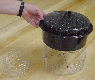 The third main area of focus is in the cooking containers used. The present cooking vessel for the Solar Funnel Cooker is a black-painted canning jar. This method is also tedious and awkward. The canning jars can be hard to clean, and they can break. Design changes are tested that would allow people to use their own cookware. This too would make the cooker more convenient to use. The fourth area of testing pitted the wooden block support which we have been using for years against a rabbit-wire support. A rabbit-wire cylinder holds the cooking vessel up off the bottom of the cooker, and allows sunlight to strike essentially all surfaces of the cooking vessel, including the bottom. The effectiveness of these methods is tested and compared both qualitatively and quantitatively. In addition to acquiring temperature-rise versus time data, we also cooked numerous meals in the solar cookers so as to get hands-on experience with cooking. Several students participated in these cooking tests. Cooker Designs: Several solar cooker designs were used during these tests. The Solar Funnel Cooker was the main cooker tested. A Solar CooKit and a bowl-shaped variation of the Solar Funnel Cooker were also tested. Most experiments were comparative tests between the various designs, and the cooker set-up was varied from test to test. The basic design of the Solar Funnel Cooker is a funnel-shaped aluminium Mylar collector. A highly reflective material is necessary to collect and concentrate the sun’s rays. The funnel walls are at a 60 degree angle (with respect to the horizontal) since this collects sunlight for a two hour time period without requiring re-orientation to follow the sun. Due to the way the Mylar sheets are cut and folded, a pair of wings on opposite ends of the funnel is formed. The wings increase the collector size and create an elliptical shape at top. At the tips of the wings, the cooker stands about 20 inches high and has a diameter of about 28 inches. At the top, along the minor axis of the elliptical funnel, the cooker stands about 15 inches high, and has a diameter of about 20 inches. Since the Aluminium Mylar does not support itself well, a nine inch diameter by five inch high bucket is used to support the funnel. 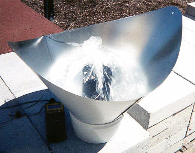 The cooking container primarily tested is a glass canning jar that has been painted flat black. The black paint allows the jar to absorb the sun’s rays. The canning jar works well due to the added pressure-cooker effect caused by the rubber ring on the inside of the lid. A black-enamel pot and a black-painted stainless steel canister were also used. We found immediately that raising the vessel off the bottom of the cooker using a rabbit-wire stand provided more rapid and even heating than the wooden block used previously. Placing the jar or pot on a wire stand allows as much reflected light onto the cooking vessel as possible. This allows even the bottom of the cooking container to absorb thermal energy that is reflected off the lower portion of the funnel. Two methods of closing the cookers off from convection currents were used. It is important to keep the air that surrounds the container from circulating, thus keeping the cooking container from being cooled by convection currents or breezes. This first method used was to enclose the cooking vessel and wire stand in a clear plastic bag, such as a heat resistant Reynolds Oven Bag. It is important to make sure that the bag is not touching the cooking vessel, so once the vessel is placed into the clear bag, air is blown into the bag and the bag is tied off. This is the most common method used for solar panel cookers, such as the Solar CooKit, because of the bags’ ability to withstand the temperatures attained in these types of cookers. But these bags tear rather easily and they are not readily available in developing countries and must be imported. The second method of closing off the cooking vessel from convection currents, designed by Dr. Jones, is to place a clear plastic disk down into the funnel above the cooking vessel. The funnel used in the test was a conventional-shaped funnel that was constructed out of thin sheet metal and aluminium-foil lined for better reflectivity. The diameter of this funnel is about 30 inches at the top, and it stands about 16 inches high. The walls also form about a 60 degree angle with respect to the horizontal. This funnel was designed to hold a larger cooking container such as a pot. The diameter of the plastic disk is large enough that the disk does not touch the top of the container. For the experiments that tested this method, a one-sixteenth inch (1.6 mm) thick Lexan disk was used. Data Collection To collect the temperatures as a function of time, a Texas Instruments Calculator Based Laboratory (CBL) was used. This portable interface is capable of recording real-time data from multiple channels. The data were downloaded into a graphing calculator, where they can be analysed and graphed immediately. From the calculator, the data can be transferred to a computer spreadsheet such as Microsoft Excel for further analysis. Due to the nature of these experiments and the low cost to purchase the CBL, this is an ideal data collector to use. A graphing calculator was used to program the CBL and to tell it what data to collect, how many points to collect, and the time period between data points collected. Since the CBL does not have any internal programs for data collection, a program must be written into the graphing calculator. There are ready-made programs that can be uploaded into the calculator, or a custom program can be made to fit the needs of the test. The program that the CBL used allowed multiple thermocouples to collect data simultaneously. To ensure that the thermocouples were calibrated against each other, both were run on the same constant temperature sample in very close proximity. Both temperature probes agreed to within 0.21oC of each other. For these experiments, this temperature difference was considered to be acceptable. Procedure Each experiment was conducted on the campus of Brigham Young University during mid-day, usually between 11:00 am and 2:00 pm to ensure that the sun was close to being directly over-head. This allowed as much sun light as possible to enter the solar collector. Each experiment included several steps, as listed below. Before each experiment was set up, the volume of the water and the mass of the container were measured and recorded. The heat capacity of the water and the container were also found. The area of the cooker perpendicular to the sun’s rays was also measured. To collect temperature data using thermocouple probes, small holes were drilled into the top of the canning jar and stainless steel canister lids. The jar and canister were both painted ultra-flat black to absorb as much of the sun’s energy as possible. On the morning of each test, the designated volume of water was measured out and poured into the cooking vessel. This volume ranged from 0.6 litre for one-quart jars, to 1.2 litters for half-gallon canning jars. For simultaneous testing, the same amount of water was poured into each container. The temperature probes were wired through the holes in the lids of the containers and secured about 13 mm into the water. For comparative tests, the probes were placed the same depth into the water to ensure that the probes did not read different measurements due to depth-related temperature differences within the containers. To enable later analysis; the time, ambient temperature, and solar irradiance were also noted and recorded. These numbers gave a reference point for each test. Each cooker that was to be tested was then completely set up. The temperature probes were secured through the lids, and the jar was placed into the clear oven bag – supported by a wire cage. Each bag was inflated so that no part of the bag touched the sides or top of the cooking container. The cord from the thermocouple to the CBL was passed through the top of the bag, and the bag was tied off with a twist-tie. The test began once both cookers were completely ready and the CBL had been programmed. Care was taken to block the sun from radiating directly onto the cookers until both were ready to begin. This ensured that the water in both cookers started at very nearly the same temperature. Most tests were set up to collect one data point every four to five minutes, for up to two hours. This allowed the cooker temperatures to reach maxima and then remain at a nearly constant temperature. Once a test was complete, the cooker was disassembled and the data downloaded into the graphing calculator. Though the graphing calculator does allow analysis, a spread sheet such as Microsoft Excel is easier to use. Thus, the data from each test were downloaded from the calculator into Microsoft Excel. The elapsed time (in seconds) and the corresponding temperatures were listed next to each other. A graph of temperature versus time was made, with the Time being the horizontal axis for each test. For comparative tests, the Temperature versus Time data for both cookers was plotted on the same graph. As a reference, a trend-line was fitted to the linear portion of the graph, along with the linear regression and the coefficient of correlation (R2). It is important to have a coefficient of correlation close to one, as this is how close the linear regression fits the data. In a separate column, the temperatures were again listed, however only from 30oC to 70oC. The change in temperature for every ten or twelve minutes was found and logged next to the temperature column. The power output (in Watts) of each cooker could then be calculated. To calculate the power output of the cookers for each specific test, the mass of the water and of the container were both measured. Though the thermal energy content of the container was relatively small compared to that of water (due to the large heat capacity of water), it was important to add it into the calculation. Also, since several different containers were compared, the energy content of the container was important. The power is found by:  The power is found in Watts. A power output for each change in temperature for the time interval is calculated and logged next to the T column. Since there are uncertainties in all of the measurements, it is important to include the error in each power output. To do this, the error in the water’s and container’s measurements is taken into consideration. The error is found by:  Where ±dP is the total error in the calculated error, dmw and dmc are the error in the mass of the water and container respectively, delta-Tp is the error in the temperature difference, and delta-t is the error in the time interval. This simplifies to:  The error was found only for the average change in temperature, rather than for each individual temperature measurement. Since the power output is dependant on the amount of energy coming in from the sun, the cooker efficiency is a good factor to calculate. To find the efficiency, the total amount of local solar radiation must be known. This should be given in watts per square metre, so that the input wattage can be found. To find the power coming in, the area of the cooker perpendicular to the sun’s rays was multiplied by the solar radiation to give the amount of power that was being collected by the cooker. Since the Solar Funnel is able to be kept on track with the sun, and since the tests were done during mid-day, it was not necessary to calculate any angles. The efficiency is simply the power output divided by the power input. The solar radiation for each test was supplied by the Department of Physics and Astronomy weather station at Brigham Young University in Provo, UT, where the tests took place. Results: Matt vs. Mirror: Several tests were conducted on the matt versus mirror finishes. In each test, the matt finish outperformed the mirror finish. On 27 July, 2001, a matt funnel and a mirror funnel were simultaneously tested with 650 cc of water. The average power output for the mirror finish was 46.4 W ± 1.7 W, while the matt funnel put out an average of 59.4 W ± 2.1 W. The efficiency of the mirror funnel was 15.8%, while the matt was 20.2% efficient. The following graph shows the temperatures reached by the matt and mirror funnels.  Channel 1 (Ch1) was the mirror finish, and channel 2 (Ch2) was the matt finish. This shows that both funnels peaked at about the same temperature: 97oC (207oF). The matt funnel peaked in about 76 minutes, whereas the mirror funnel peaked in 96 minutes, twenty minutes later. Though this perhaps a tolerable time difference for actual cooking, it is substantial. Every matt vs. mirror test performed in a similar way. These results are due to the way the matt funnel reflects the sun’s rays. The mirror finish seems to focus a strip of light onto the cooking vessel more than the matt finish does. As a result, the matt finish diffuses the light more and the cooker is heated more uniformly. This is good, since the matt finish is easier to work with, delivering much less glare to the eyes. The following graph shows the temperature rise with time for a Solar CooKit:  Comparing the two graphs above, we find that the Solar CoolKit performed very well, comparable to the Funnel Cooker. We should note that in both cases, we used a canning jar (pressurised) supported by a wire stand. We found that the wire stand improves the performance of the Solar CooKit significantly and hope that this support stand will be used in countries where the Solar CooKit is in use. In tests where the use of the clear plastic disk was tested against the oven-bag, an aluminium pot was used in the disk-set-up. In these tests, the cooker with an oven bag outperformed the cooker using a plastic disk. On 10 August, 2001, a test was run which compared the disk/pot set-up against the oven-bag/jar set-up. Both cookers follow similar heating paths with time, but the oven-bag/jar did slightly better. Due to the higher mass of the jar compared to the mass of the aluminium pot, and the much higher heat capacity of the water, the average power output for the oven-bag/jar was 39.8 ± 1.4 W, while the disk/pot put out 30.3 W ± 1.2 W. The efficiency of the oven-bag/jar was 14.7% and the efficiency of the disk/pot set-up was 10.4% for this test. This is also partly due to the pressure-cooker effect that the canning jar produces. Though this is a considerable efficiency difference, the disk/pot set-up did very well in subjective tests where food was actually cooked and tasted. In all cases where the disk/pot set-up was used to cook food, the food cooked in about the same amount of time. The ease of the disk/pot set-up is also an important consideration. Overall, in tests where food was cooked, the disk/pot set-up was preferred over the oven-bag/jar set-up. Conclusions: As many countries are depleting their natural resources due to increased population and the resulting deforestation, methods other than burning wood are needed to cook food and pasteurise water. Solar cookers provide a sustainable technology that relies on the sun’s free energy. We report several advances to make them better. The need for cheap and effective solar cookers is very great and growing. The Solar Funnel Cooker has been designed to meet the growing need by being inexpensive and effective. We determined that the Solar CooKit was nearly as effective when a rabbit-wire stand was used to support the cooking vessel. By collecting time vs. temperature data, quantitative analysis has been done. This analysis approach is useful for further development of the cookers. Several areas of research were explored in 2001. Two finishes were tested for the reflector, a matt finish and a mirror finish. The benefits of the matt over the mirror finish are: 1) The matt finish is easier to work over because the sun’s glaring reflection is diffused, and 2) the matt finish out-performs the mirror finish in temperature vs. time tests. The method of closing off the cooker from convection current was tested and compared with an alternative method – a clear plastic disk. The use of a pot rather that a canning jar was also tested. Though the present oven-bag/jar method does outperform the disk/pot method, the disk/pot method is easier to use and seems to be nearly as efficient. Finally, we showed that a wire-mesh stand is a considerable improvement over the use of a wooden block or other opaque stand for the cooking vessel. We join with our fellow researchers around the world in pursuing further development of solar cookers, particularly to benefit people in developing countries. References: [1]. Jones, Steven E. et al., BYU. [2]. Wattenberg, Frank. Montana State University. 1996. [2]. Wattenberg, Frank. Montana State University. 1996.Error! Reference source not found.  The main purpose of solar cookers is to change sunlight into heat which is then used to cook foods. We are all familiar with how successful solar cookers are at cooking and baking a wide variety of foods. In this article I want to consider using the heat in solar cookers for purposes other than cooking. My main focus will be solar water pasteurisation, which can complement solar cooking and address critical health problems in many developing countries. The majority of diseases in developing countries today are infectious diseases caused by bacteria, viruses, and other microbes which are shed in human faeces and polluted water which people use for drinking or washing. When people drink the live microbes, they can multiply, cause disease, and be shed in faeces into water, continuing the cycle of disease transmission. World-wide, unsafe water is a major problem. An estimated one billion people do not have access to safe water. It is estimated that diarrhoeal diseases that result from contaminated water kill about 2 million children and cause about 900 million episodes of illness each year. Boiling contaminated water How can infectious microbes in water be killed to make the water safe to drink? In the cities of developed countries this is often guaranteed by chlorination of water after it has been filtered. In developing countries, however, city water systems are less reliable, and water from streams, rivers and some wells may be contaminated with human faeces and pose a health threat. For the billion people who do not have safe water to drink, what recommendation do public health officials offer? The only major recommendation is to boil the water, sometimes for up to 10 minutes. It has been known since the time of Louis Pasteur 130 years ago that heat of boiling is very effective at killing all microbes which cause disease in milk and water. If contaminated water could be made safe for drinking by boiling, why is boiling not uniformly practised? There seem to be five major reasons:
If wood, charcoal, or dung is used as fuel for boiling water, the smoke creates a health hazard, as it does all the time with cooking. It is estimated that 400 to 700 million people, mainly women, suffer health problems from this indoor air pollution. As a microbiologist, I have always been perplexed as to why boiling is recommended, when this is heat far in excess of that which is necessary to kill infectious microbes in water. I presume the reason boiling is recommended is to make sure that lethal temperatures have been reached, since unless one has a thermometer it is difficult to tell what temperature heated water has reached until a roaring boil is reached. Everyone is familiar with the process of milk pasteurisation. This is a heating process which is sufficient to kill the most heat resistant disease causing microbes in milk, such as the bacteria which cause tuberculosis, undulant fever, streptococcal infections and Salmonellosis. What temperatures are used to pasteurise milk? Most milk is pasteurised at 71.7o C (161o F) for only 15 seconds. Alternatively, 30 minutes at 62.8o C (145o F) can also pasteurise milk. Some bacteria are heat resistant and can survive pasteurisation, but these bacteria do not cause disease in people. They can, however, spoil the milk, so pasteurised milk is kept refrigerated. There are some different disease microbes found in water, but they are not unusually heat resistant. The most common causes of water diseases, and their heat sensitivity, are presented in Table 1. The most common causes of acute diarrhoea among children in developing countries are the bacteria Escherichia coli and Shigelia SD. and the Rotavirus group of viruses. These are rapidly killed at temperatures of 60o C or greater. Solar water pasteurisation As water heats in a solar cooker, temperatures of 56o C and above start killing disease-causing microbes. A graduate student of mine, David Ciochetti, investigated this for his master's thesis in 1983, and concluded that heating water to 66o C in a solar cooker will provide enough heat to pasteurise the water and kill all disease causing microbes. The fact that water can be made safe to drink by heating it to this lower temperature - only 66o C - instead of 100o C (boiling) presents a real opportunity for addressing contaminated water in developing countries. Testing water for faecal contamination How can one readily determine if the water from a well, pump, stream, etc. is safe to drink? The common procedure is to test the water for bacterial indicators of faecal pollution. There are two groups of indicators which are used. The first is the coliform bacteria which are used as indicators in developed countries where water is chlorinated. Coliform bacteria may come from faeces or from plants. Among the coliform bacteria is the second indicator, Escherichia coli. This bacterium is present in large numbers in human faeces (approximately 100,000,000 per gram of faeces) and that of other mammals. This is the main indicator used if water is not chlorinated. A water source containing 100 E. coli per 100 ccs poses a substantial risk of disease. The standard method of testing water for the presence of coliforms and E. coli requires trained personnel and a good laboratory facility or field unit which are usually not present in developing countries. Thus, water supplies are almost never tested. A new approach to testing in developing countries In 1987, the Colilert MPM Test (CLT) was introduced as the first method which used a defined substrate technology to simultaneously detect coliforms and E. coli. The CLT comes as dry chemicals in test tubes containing two indicator nutrients: one for coliforms and one for E. coli. The CLT involves adding 10 ml of water to a tube, shaking to dissolve the chemicals, and incubating at body temperature for 24 hours. I prefer incubating tubes under my belt against my body. At night I sleep on my back and use night clothes to hold the tubes against my body. If no coliform bacteria are present, the water will remain clear. However, if one or more coliforms are present in the water, after 24 hours their growth will metabolise ONPG and the water will change in colour from clear to yellow (resembling urine). If E. coli is among the coliform bacteria present, it will metabolise MUG and the tube will fluoresce blue when a battery-operated, long-wave ultraviolet light shines on it, indicating a serious health hazard. I have invited participants at solar box cooker workshops in Sierra Leone, Mali, Mauritania, and Nepal to test their home water supplies with CLT. One hundred and twenty participants brought in samples. In all four countries, whether the water was from urban or rural areas, the majority of samples contained coliforms, and at least half of these had E. coli present. Bacteriological testing of the ONPG and MUG positive tubes brought back from Mali and Mauritania verified the presence of coliforms/E. coli in approximately 95% of the samples. It is likely that soon the Colilert MPN test will be modified so that the test for E. coli will not require an ultraviolet light, and the tube will turn a different colour than yellow if E coli is present. This will make the test less expensive and easier to widely use in developing countries to assess water sources. Effect of safe water on diarrhoea in children What would be the effect if contaminated water could be made safe for drinking by pasteurisation or boiling? One estimate predicts that if in the Philippines, families at present using moderately contaminated wells (100 E. coli per 100 ml) were able to use a high-quality water source, diarrhoea among their children would be reduced by over 30%. Thus, if water which caused a MUG (+) test were solar pasteurised so it would be clear, this would help reduce the chance of diarrhoea, especially in children. Water pasteurisation indicator  How can one determine if heated water has reached 65o C? In 1988, Dr. Fred Barrett (USDA, retired) developed the prototype for the Water Pasteurisation Indicator (WAPI). In 1992, Dale Andreatta, a graduate engineering student at the University of California, Berkeley, developed the current WAPI. The WAPI is a polycarbonate tube, sealed at both ends, partially filled with a soybean fat which melts at 69o C ("MYVEROL" 18-06K, Eastman Kodak Co., Kingsport, TN 37662). The WAPI is placed inside a water container with the fat at the top of the tube. A washer will keep the WAPI on the bottom of the container, which heats the slowest in a solar box cooker. If heat from the water melts the fat, the fat will move to the bottom of the WAPI, indicating water has been pasteurised. If the fat is still at the top of the tube, the water has not been pasteurised. The WAPI is reusable. After the fat cools and becomes solid on the bottom, the fish line string is pulled to the other end and the washer slides to the bottom, which places the fat at the top of the tube. Another pasteurisation indicator has been developed by Roland Saye which is based on expansion of a bi-metal disc which is housed in a plastic container. This also shows promise and is in the early testing stages. The WAPI could be useful immediately for people who currently boil water to make it safe to drink. The WAPI will indicate clearly when a safe temperature has been reached, and will save much fuel which is currently is being wasted by excessive heating. 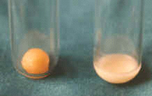 [Editor's note: Using Beeswax & Carnauba Wax to Indicate Temperature: In SBJ #15 we discussed using beeswax, which melts at a relatively low 62o C, as an indicator of pasteurisation. We have now found that mixing a small amount of carnauba was with the beeswax (~1:5 ratio) raises the melting temperature of the beeswax to 70o - 75o C. Carnauba wax is a product of Brazil and can be bought in the US at woodworking supply stores. Further testing needs to be done to confirm that the melting point remains the same after repeated re-melting. Different strategies for solar water pasteurisation The solar box cooker was first used to pasteurise water. David Ciochetti built a deep-dish solar box cooker to hold several gallons of water. At this time of the year in Sacramento, three gallons could be pasteurised on our typical sunny days. Dale Andreatta and Derek Yegian of the University of California. Berkeley, have developed creative ways to greatly increase the quantity of water which can be pasteurised, as we will hear about at this conference. I am also excited about the possibility of pasteurising water using the simple solar panel cookers. By enclosing a dark water container in a polyester bag to create an insulating air space, and by using lots of reflectors to bounce light onto the jar, it is possible to pasteurise useful amounts of water with a simple system. It takes about four hours for me to pasteurise a gallon of water in the summer with the system I am using. Solar panel cookers open up enormous possibilities for heating water not only for pasteurisation, but also for making coffee and tea, which are quite popular in some developing countries. The heated water can also be kept hot for a long time by placing it in its bag inside an insulated box. In the insulated container I use, a gallon of 80o C water will be approximately 55o C after 14 hours. Water at a temperature of 55o C will be about 40o C after 14 hours, ideal for washing/shaving in the morning. I will close with some advice from the most famous microbiologist, who pioneered the use of vaccinations in the 1890s: Louis Pasteur. When he was asked the secret of his success, he responded that above all else, it was persistence. I will add that you need good data to be persistent about, and we certainly have that with solar cookers; the work in Sacramento, Bolivia, Nepal, Mali, Guatemala, and wherever else the sun shines. Continued overuse of fuel-wood is non-sustainable. We need to persist until the knowledge we have spreads and becomes common knowledge world-wide. For questions or comments contact Dr. Robert Metcalf at. Dr. Robert Metcalf 1324 43rd St. Sacramento, California 95819 USA. IDEXX Laboratories, Inc. makes the Colilert kit and is located at this address: IDEXX Laboratories, Inc. One IDEXX Drive Westbrook, ME 04092 USA Voice: (800) 321-0207 or (207) 856-0496 Fax: (207) 856-0630 Editor's Note: Testing Water in Developing Countries The Colilert system makes it possible to test water without the need for a laboratory. IDEXX Laboratories, the manufacturer, recommends that you use five test tubes for each sample. Bob Metcalf explains that five tubes would comprise 50 ml, which is the minimum sample size permitted by US law. This is an unrealistically high standard by which to judge the water in developing countries where you are examining water that is already being drunk, in spite of the fact that it may be making people sick. By using a single test tube (10 ml) there is a very small chance that your sample missed the small number of bacteria that might have been present. IDEXX Laboratories will also tell you that you need an incubator to achieve valid results. Again, Bob Metcalf tells us that all that is needed is to keep the tubes close to your body for 36 hours, since body temperature is the correct incubation temperature. What you are actually measuring in the test is the presence of 1) coliform bacteria, and 2) E. coli, a type of coliform bacteria that is largely found in faecal matter. A positive test for coliform bacteria might be due to coliform bacteria that has washed off of plant leaves , and thus be fairly innocuous. A positive test for E. coli, however, would indicate that any bacteriological contamination was from a faecal source, which might also contain Giardia, cholera, or other serious infectious microbes. This document is published as part of The Solar Cooking Archive. 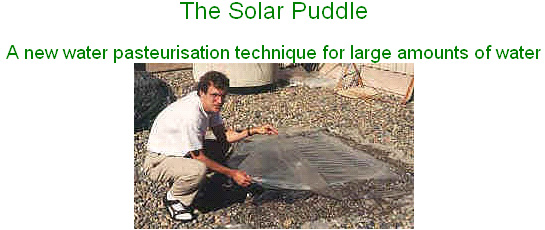 The lack of clean drinking water is a major health problem in the developing world. To reduce this health risk ways of producing clean water at an affordable cost are needed, and people need to be educated about germs and sanitation, lest they accidentally re-contaminate their clean drinking water. Recently, several of us at the University of California at Berkeley have attacked the first of these requirements. Previous issues of this newsletter have included stories about our water pasteurisation indicator and our flow-through water pasteurises based on a design by PAX World Service. In this article we describe a new low-cost device that pasteurises water. For those not familiar with the pasteurisation process, if water is heated to 149O F (65o C) for about 6 minutes all the germs, viruses, and parasites that cause disease in humans are killed, including cholera and hepatitis A and B. [Ed. We have reports from the field that at 145o F (63o C) in a solar puddle, bacterial growth might actually be increased. Since this temperature is very close to the minimum pasteurisation temperature mentioned in this article, we suggest that you heat the water to a higher temperature and perform tests before adopting a solar puddle as your method of pasteurisation]. This is similar to what is done with milk and other beverages. It is not necessary to boil the water as many people believe. Pasteurisation is not the only way to decontaminate drinking water, but pasteurisation is particularly easy to scale down so the initial cost is low. The new device is called a solar puddle, and it is essentially a puddle in a greenhouse. One form of the solar puddle is sketched in the figure below, though many variations are possible.  One begins by digging a shallow pit about 4 inches deep. The test device was a "family-size" unit, about 3.5 feet by 3.5 feet, but the puddle could be made larger or smaller. If the puddle is made larger there is more water to pasteurise, but there is also proportionately more sunshine collected. The pit is filled with 2 to 4 inches of solid insulation. We used wadded paper, but straw, grass, leaves, or twigs could be used. This layer of insulation should be made flat, except for a low spot in one corner of the puddle. Put a layer of clear plastic and then a layer of black plastic over the insulation with the edges of the plastic extending up and out of the pit. Two layers are used in case one develops a small leak. We used inexpensive polyethylene from a hardware store, though special UV stabilised plastic would last longer. Put in some water and flatten out the insulation so that the water depth is even to within about 0.5 inch throughout the puddle, except in the trough which should be about 1 inch deeper than the rest. Put in more water so that the average depth is 1 to 3 inches depending on how much sunshine is expected. A pasteurisation indicator (available from Solar Cookers International at 916/455-4499) should go in this trough since this is where the coolest water will collect. Put a layer of clear plastic over the water, again with the edges extending beyond the edges extending beyond the edges of the pit. Form an insulating air gap by putting one or more spacers on top of the third layer of plastic (large wads of paper will do) and putting down a fourth layer of plastic, which must also be clear. The thickness of the air gap should be 2 inches or more. Pile dirt or rocks on the edges of the plastic sheets to hold them down. The puddle is drained by siphoning the water out, placing the siphon in the trough and holding it down by a rock or weight. If the bottom of the puddle is flat, well over 90% of the water can be siphoned out. Once the puddle is built it would be used by adding water each day, either by folding back the top two layers of plastic in one corner and adding water by bucket, or by using a fill siphon. The fill siphon should NOT be the same siphon that is used to drain the puddle, as the fill siphon is re-contaminated each day, while the drain siphon MUST REMAIN CLEAN. Once in place the drain siphon should be left in place for the life of the puddle. The only expensive materials used to make the puddle are a pasteurisation indicator (about $2 for the size tested). All of these items are easily transportable, so the solar puddle might be an excellent option for a refugee camp if the expertise were available for setting them up. Many tests were done in the spring and summer of this year in Berkeley, California. On days with good sunshine the required temperature was achieved even with 17 gallons of water (2 1/2 inch depth). About 1 gallon is the minimum daily requirement per person, for drinking, brushing one's teeth, and dish washing. With thinner water layers higher temperatures can be reached. With 6 gallons (1 inch depth) 176o F was achieved on one day. The device seems to work even under conditions that are not ideal. Condensation in the top layer of plastic doesn't seem to be a problem, though if one gets a lot of condensation the top layer should be pulled back to let the condensation evaporate. Small holes in the top layers don't make much difference. The device works in wind, or if the bottom insulation is damp. Water temperature is uniform throughout the puddle to within 2o F. After some months the top plastic layers weaken under the combined effects of sun and heat and have to be replaced, but this can be minimised by avoiding hot spots. Another option would be to use a grade of plastic that is more resistant to sunlight. The two bottom layers of plastic tend to form tiny tears unless one is very careful in handling them, (that is why there are two layers on the bottom). A tiny hole may let a little water through and dampen the solid insulation, but this is not a big problem. There are many variations of the solar puddle. We've been able to put the top layer of plastic into a tent-like arrangement that sheds rain. This would be good in a place that gets frequent brief showers. Adding a second insulating layer of air makes the device work even better, though this adds the cost of an extra layer of plastic. As mentioned the device can cover a larger or smaller area if more or less water is desired. One could make a water heater by roughly tripling the amount of water so that the maximum temperature was only 120° F or so, and this water would stay warm well into the evening hours. This water wouldn't be pasteurised though. One could help solve the problem of dirty water vessels by putting drinking cups into the solar puddle and pasteurising them along with the water. The solar puddle could possibly cook foods like rice on an emergency basis, perhaps in a refugee camp. You can contact Dr. Dale Andreatta S. E. A. Inc. 7349 Worthington-Galena Rd. Columbus, OH 43085 (614) 888-4160 FAX (614) 885-8014 web link 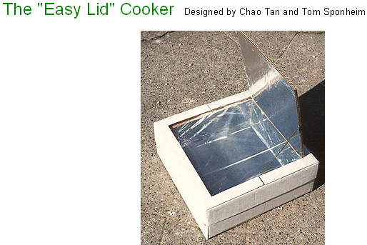 Although designs for cardboard cookers have become more simple, fitting a lid can still be difficult and time consuming. In this version, a lid is formed automatically from the outer box. Making the Base Take a large box and cut it in half as shown in Figure 1. Set one half aside to be used for the lid. The other half becomes the base.  Fold an extra cardboard piece so that it forms a liner around the inside of the base (see Figure 2).  Use the lid piece as shown in Figure 3 to mark a line around the liner.  Cut along this line, leaving the four tabs as shown in Figure 4.  Glue aluminium foil to the inside of the liner and to the bottom of the outer box inside. Set a smaller (inner) box into the opening formed by the liner until the flaps of the smaller box are horizontal and flush with the top of the liner (see Figure 5). Place some wads of newspaper between the two boxes for support.  Mark the underside of the flaps of the smaller box using the liner as a guide. Fold these flaps down to fit down around the top of the liner and tuck them into the space between the base and the liner (see Figure 6). Fold the tabs over and tuck them under the flaps of the inner box so that they obstruct the holes in the four corners (see Figure 6).  Now glue these pieces together in their present configuration. As the glue is drying, line the inside of the inner box with aluminium foil. Finishing the Lid Measure the width of the walls of the base and use these measurements to calculate where to make the cuts that form the reflector in Figure 7. Only cut on three sides. The reflector is folded up using the fourth side as a hinge. Glue plastic or glass in place on the underside of the lid. If you are using glass, sandwich the glass using extra strips of cardboard. Allow to dry.  Bend the ends of the wire as shown in Figure 7 and insert these into the corrugations on the lid and on the reflector to prop open the latter. Paint the sheet metal (or cardboard) piece black and place it into the inside of the oven. Improving Efficiency Glue thin strips of cardboard underneath the sheet metal (or cardboard) piece to elevate it off of the bottom of the oven slightly. Cut off the reflector and replace it with one that is as large as (or larger than) the entire lid. This reflects light into the oven more reliably. Turn the oven over and open the bottom flaps. Place one foiled cardboard panel into each airspace to divide each into two spaces. The foiled side should face the centre of the oven.  ******************** Water Collection Systems. Getting adequate drinking water can often be a problem as there are many places where the local water supply is heavily contaminated with poisons, deadly organisms or both. While it is definitely much better to drink purified water than seriously contaminated water, it should be understood that most of the systems mentioned here, produce either distilled water or something very close to distilled water. Drinking distilled water for more than a few weeks is not ideal as distilled water is able to dissolve almost anything and it can do that perfectly well inside your body, removing essential minerals and other important items. So, if possible, avoid drinking distilled water for lengthy periods of time unless there is no other option other than seriously contaminated water carrying diseases and poisons:  This effect is very noticeable on foggy days where trees drip water extensively due the fog depositing moisture on the leaves and branches. At www.wired.com there is shown a very large (and comparatively expensive at £1000 each) and very elegantly designed version of this, designed in Italy and called the “warkawater” tower:  Supplied in kit form, using structural members made of bamboo, this unit is 4 metres wide and 9 metres tall with rotating mirrors to scare birds away. With passive water collection from fog, rain and dew, tested in Ethiopia it can produce between 50 and 100 litres per day. The condensation material is plastic netting. An emergency measure where water is needed, is to fasten a clean plastic bag around a branch of a tree. Trees lift a large amount of water through their root systems and a good deal of that water exist from the leaves of the tree. The plastic bag intercepts that moisture loss and collects it as clean water:  Another emergency measure is to use a clean plastic sheet and a hole dug in the ground. A clean container is placed in the centre of the hole and the plastic sheet used to cover the hold. The sheet is held around the edges of the hole with stones or any other suitable heavy material – bricks, timber, etc. A weight is then placed in the centre of the plastic sheet, pulling it down into a slope in every direction and forming an inverted peak over the container:  The area under the plastic sheet is heated by the greenhouse effect. Moisture also comes from the earth inside the enclosed hole. The moisture in the air in the cavity condenses on the underside of the plastic sheet. But as the plastic sheet is shaped into an inverted pyramid due to the weight just above the container, the water runs down and drips into the container. Again, no input power required and no moving parts. While these methods produce good quality water which is effectively distilled water, it should not be considered to be sterile and immediately ready for human consumption, even though any risk from drinking it ‘as-is’ is likely to be very low. There will always be air-borne pathogens, and the ‘clean’ components used to collect the water in the first place may not be as clean as was thought. The same applies to the excellent quality water produced by dehumidifiers, where the inner working surfaces cannot be considered sterile after the equipment has been used for any length of time. To raise the water quality, boiling briefly, microwaving the water or it to UV radiation should kill any remaining harmful organisms in the water and make it fit for consumption. Applying these same methods on a more permanent basis, leads to the construction of devices of the following type which can produce clean water at the rate of 4 litres for every 8 square feet (0.75 square metres) of glass area in just 5 hours of sunshine:  There can be many variations on this shape. These devices are generally built either with glass lids or the whole construction in acrylic sheet. Here, the greenhouse effect heats the inside of the box, causing evaporation of the water inside. This condenses on the walls and lid of the box, where it runs down and into the clean-water section. This particular design can be further enhanced as shown on the http://www.permapak.net/solarstill.htm web site, where the heating inside the box is upgraded by using black high-temperature silicone to coat the inside of the bottom of the case. The black material absorbs sunlight particularly well and so helps to heat the water. Another enhancement is to place a reflector, possibly made from aluminium foil, behind the unit in order to increase the amount of sunlight or UV radiation reaching the water inside the box:  The web site www.gabrielediamanti.com shows details of what is considered to be a very effective, low-cost unit aimed at undeveloped countries. Please visit that site where there is a ‘Donations’ button which allows you to support this excellent work. The designer Gabriele Diamanti says “Eliodomestico is an open project, free to the people who need it. I would really appreciate if you would like to help me in the development of this project!”. It works like this:    Very simple systems: It is usually presumed that quite a bit of expenditure and construction is needed to make a solar still which will purify water. That is not necessarily the case. Here is a design which can cost nothing and which can work well in a sunny location:  This arrangement could hardly be more simple than it is. An inner container is used and it is made either from a dark material or is painted black, preferrably, matt black as a shiny black reflects more of the light falling on it than a matt black surface does. In the diagram above, the black stops well short of the top of the inner container, but that is only to show the liquid inside the container and in fact, the inner container will be dark from top to bottom. Because of this dark colour, the liquid inside the inner container gets hotter than the air outside it (which is hotter than the air outside the outer container, due to the greenhouse effect). There is considerable evaporation from the inner container, but as it can’t escape, it forms droplets on the inside of the outer container and these droplets slide down and collect at the bottom of the container, forming a reservoir of distilled water which is safe to drink. The construction of this still can be from things which are already to hand. For example, the bottom can be cut off a transparent plastic drinks bottle and used to cover a dark glass drinks bottle standing in an ordinary bowl, as shown here: 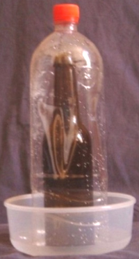 It is, of course, essential for the outside of the glass bottle and the inside of the plastic bottle to be completely clean so that they do not contaminate the purified water. Another variation on this is to use a dark glass jar inside a plasitc storage jar, again, placed inside an ordinary bowl as shown here: 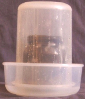 Alternatively, a plastic jar with a screw lid can be used upside down and the lid used to replace the bowl. The inner container in this case, happens to be plastic. The capacity of the lid limits the amount of clean water which can be produced at any one time, unless the lid is carefully removed and a larger bowl used to catch the clean water (which means that it would have been easier to use the bowl instead of the lid): 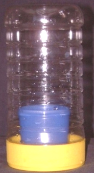 Water Purity and Quality There are two main factors involved in pure drinking water: 1. Debris and other non-biological material. 2. Biological material. It is necessary to deal with each of these problems. 1. Non-biological material is avoided if the water is gathered by any of the evaporation/distillation systems shown above as the solids, sea-salts, mud or whatever, gets left behind. The same applies to collecting the evapotranspiration water from a tree using a clean plastic bag as mentioned above. If it is necessary to use stagnant, muddy water or water from a polluted river, then two things can be done. The first thing is to get the water as clean as possible before collecting it. If it is possible, dig a hole near the water supply, making the hole deeper than the bed of the river or pool. That causes the hole to fill partially with water coming from the source through the ground which acts as a filter and as a result, the water in the hole is likely to have a lower level of solids in it. Having extracted the water from the new hole, unless it is exceptionally good quality, it can be improved by filtering it through sand held in a cloth material, or even just through a fine-mesh cloth. Water can generally be found under the bed of a dried out river and the best point to dig is at the outside of a bend in the river bed. 2. Biological material is a serious hazard and it can make you very ill and/or kill you. The evaporation systems mentioned above, generally avoid this problem, but the safe method for producing safe drinking water is to boil it for at least ten minutes as that kills the organisms in the water, making it safe. Unfortunately, that requires a good deal of fuel and the water needs to cool afterwards. Mixing ozone into the water or shining ultraviolet light through the water are alternatives. Be very careful as even moistening your lips with contaminated water can make you severely ill. Water in a fast-flowing or bubbling stream flowing over rocks and sand, should be safe to drink provided that there is a stretch of 10 metres (30 feet) upstream of the sampling point, which is free from contaminants (dead animals, effluent inflow, etc.) as the movement of the water mixes air into the water and the oxygen in the air kills the bacteria. A very effective way of dealing with polluted water (and any illness caused by it) is to add some colloidal silver to it, as that deals with all serious pathogens and, for example, can totally clear a contaminated well. In case you are not familiar with how to make colloidal silver, details are given below. Fresh water on a larger scale: US patent 2,996,897 (22 Aug 1961) from Elmer Grimes: The fifty-year-old Grimes system is effectively an outdoor refrigerator. A series of cone-shaped metal panels are stacked together vertically to save space. Each cone has pipes inside it which pass the cooling fluid through the cones, ensuring that they are always at low temperature. In the same way that a cold drink gets water droplets on the outside of the glass, the cones get water droplets forming on them all the time. A wiper arm like a windscreen wiper on a car then brushes those droplets off, with the wiper arm rotating around the cones continuously, rather than backwards and forwards as a car wiper blade does. This produces a continuous stream of fresh water coming off the cones. Unless there is some good reason why not to, the cones are mounted in a raised position so that gravity can be used to direct the water flow to where it needs to end up. Cones are used as they have a greater surface area than a flat plate of the same diameter would have, and the downward slope of the cone helps the water droplets flow off the cone surfaces:  This invention relates to a method and apparatus for obtaining a fresh water supply from the atmosphere. In arid and semi-arid regions, the supply of fresh water is a considerable problem which has in the past, been met by the use of highly expensive apparatus, equipment and systems involving the transport of water over great distances, using equipment which is consequently very vulnerable to destruction and additionally expensive in upkeep and repair. Other types of apparatus for obtaining a fresh water supply in such regions, involves the processing of sea water which has proven to be slow and also extremely expensive for obtaining water in larger practical quantities. It is therefore a primary object of this invention to provide apparatus which is especially useful in such regions for providing a fresh water supply in a more efficient, rapid and less costly a manner. Another object is to provide a source of fresh water obtained from the atmosphere in a manner similar to a portion of the natural water cycle and by a process which avoids the high costl boiling, evaporating and pumping of sea water. A further object is to provide an apparatus which removes water from the atmosphere by condensation and precipitation for use in home and commercial purposes having the advantage of providing a more local source of water which will be naturally soft, having no scale to clog plumbing, nor any disposal problem for salt and mineral matter as occurs with seawater. An additional object is to provide apparatus for obtaining water directly from the atmosphere by condensing water vapour in the atmosphere on a number of conical condensing surfaces exposed to the air which may be cooled by the air if the air temperature is below the condensing temperature and automatically cooled by circulating refrigerant when necessary so as to provide means for continuously condensing on to the condensing surfaces, the water vapour which is in the air. Continuously operating wipers on the condensing surfaces cause the condensation on them to be swept into the bottom funnel portion of the apparatus. The water so collected is then conducted to local storage or use while the kinetic energy of the water flowing from the apparatus may be converted by means of a turbine-driven generator into useful energy which may be used to operate the motor driving the precipitation wipers as well as the compressor by means of which, the refrigerant is circulated within the condensing surface members for maintaining them at a temperature lower than the water vapour’s condensing temperature. It will therefore be apparent that the apparatus and method of this invention has the advantage of providing a continuous supply of water which may be so engineered to supply water at all times in sufficient quantities and at the same time, furnish the power for its own operation and even at times, excess power which may be used for other purposes. The apparatus and method take advantage of the potential energy acquired by water undergoing the natural waster cycle by prematurely condensing the water vapour in the atmosphere and mechanically precipitating it by a mechanism acting in concert with, and supplementing the natural phenomena.  Fig.1 is a schematic illustration of the installation and operating principles of the method and apparatus  Fig.2 is a partial sectional view with parts shown in section of the apparatus  Fig.3 is a sectional view taken substantially through a plane indicated by section line 3—3 of Fig.2  Fig.4 is a partial, enlarged sectional view of a portion of the conical condensing plate and wiper mechanism  Fig.5 is a partial sectional view taken substantially through a plane indicated by section line 5—5 in Fig.2  Fig.6 is a top plan view of an opening in the funnel portion of the apparatus as viewed from a plane indicated by section line 6—6 in Fig.2  Fig.7 is a partial sectional view taken through a plane indicated by section line 7--7 in Fig.3. Referring to the drawings in detail: Fig.1 illustrates the installation set-up. The entire apparatus is indicated by reference number 10 and includes a tank structure 12, (preferably) mounted at a height greater than the area to be supplied with the water. The water supply originates in the tank structure and is fed to the water reservoir 14 by a conduit system 18 which has a turbine 20. A portion of the kinetic energy of the water flowing in the conduit 18 is absorbed by the turbine mechanism 20 which powers and electrical generator 22 from which electricity can be drawn via a voltage regulator 24, which is connected to an electric motor 26 which is associated with the tank mechanism 12 by power lines 28. The voltage regulator 24 is also connected to external power lines 30 which may be able to supply additional power to other equipment. On the other hand, the power line may be interrelated with the mains supply so that when the power output of the generator 22 is insufficient to energise motor 26, and external source of power through the power line 30 may be used. It will also be noted from Fig.1, that an additional electrical connection 32 is provided between the power lines 28 supplied either by the generator 22 or the external power source through line 30 and voltage regulator 24 so as to operate other parts of the equipment associated with the tank structure 12 as will be explained later. Referring now to figures 2, 3, 4 and 5, it will be observed that the tank structure 12 includes a cylindrical portion 34 which is connected at the bottom to a funnel portion 36, to which the conduit 18 is connected. Water collects at the bottom of the funnel 46 and carried by conduit 18 for storage and use. On the funnel walls are a number of streamlined-shaped openings 37 with upward projecting rims enabling the circulation of moisture-laden air through the funnel portion for additional water collection, each opening being designed however to prevent flow of water from the funnel portion as seen from Fig.2 and Fig.6. It will also be observed that the motor 26 which is positioned above the open top of the cylindrical portion 34 of the tank structure 12, is mounted on the cylindrical section 34 by means of a suitable mounting structure 38 while a refrigerant circulating unit 40 is mounted within the funnel portion 36 in axial alignment with the motor 26 by any suitable supporting structure 42. In addition to the wiper of the unit 44 driven by the motor 26, the compressor mechanism 40 is also driven from the motor 26 and is connected by a thermostatically controlled disconnector mechanism 46 of any suitable design, using mains power for connecting and disconnecting using lines 32 which are there for that purpose. The specific designs for mechanism 46 are well known. It will be observed for Fig.2 and Fig.4 in particular, that the motor 26 has an output shaft 48 to which there is connected an elongated extension shaft 50 which extends downwards through tank 12 for connection to the compressor 40 through the thermostatically-controlled electrically-operated clutch 46. Also connected to the motor shaft 48 are a number of interconnected wiper arms 52 of the wiper mechanism 44. It will be observed from Fig.2 and Fig.4 that there are provided several parallel downward-inclined wiper arms 52 which are connected by axial connecting members 54. The wiper arms 52 are positioned around, and rotate with respect to, the cone-shaped parallel, vertically spaced apart, plates 56, each of which has an exposed upper condensing surface 58 and a lower condensing surface 50 which are connected at their outer edge, and at their inner edge, they are connected to the next plates vertically above and below by plate 62. As is more clearly seen in Fig.4, the plate members terminate at the top with an axial portion 64 with respect to which, the motor shaft 48 rotates, bearing 66 being positioned between motor shaft 48 and part 64 of the conical plate. Shown in Fig.3 and Fig.7, lined curved openings 63 are placed in the condensing portions 58 and 60 of the conical plate members 56 in order to accommodate the circulation of air through and between the plate members. The plate members may be held fixed with respect to the housing tank 12 while the wiper arms 52 of the wiper mechanism 44 may be rotated relative to it. Accordingly, the wiper arm 52 includes wiper material 68 which contacts the upper and lower surfaces 58 and 60 of each of the conical plate members 56 so as to wipe from them the condensation 70 formed there as more clearly seen in Fig.5. The water so precipitated falls down to collect at the bottom of the funnel portion 36 of the tank 12. It will be understood that the water vapour in the air will condense on surfaces 58 and 60 if the temperature of the air is low enough, or below, the water condensing temperature. At certain times, such as at night, the air temperature will have the conducting surface at the proper temperature. However, at other times it will be necessary to cool the condensing surface artificially by use of a conventional circulating refrigerant system. Accordingly, circulating refrigerant coils 72 are placed inside each conical plate 56. As seen more clearly in Fig.3, the coils 72 are arranged to provide cooling for the entire exposed surface of the conical condensing plate 56 between the upper and lower condensing surfaces 58 and 60 of each conical plate member as more clearly seen in Fig.4, with the lined openings 63 being located between the coils. Each cooling coil network 72 is connected by a radial connecting tube 74 (Fig.3) connected to an axial tube portion 76 (Fig.4) through which refrigerant may be pumped into the coil 72 of each of the conical plate members 56. The axial portion 76 of the cooling tube is connected at the bottom to the circulating unit 40. Refrigerant under pressure is applied to the supply tube 76 for circulation through each of the conical plate members 56 and returned through a parallel axial tube 78 as seen in Fig.2 and Fig.4. It will also be understood that although the apparatus is described in the illustrated example with stationary conical plates and rotating wiper arms, it would be possible to have the wipers fixed and the cone rotating, and in that case the rotation of the cones may provide sufficient physical disturbance through inertia and centrifugal effect to cause precipitation, in which case the wipers will not be needed. Furthermore, the number of wiper arms may be varied to suit the conditions under which the apparatus operates and the quantity of water to be derived from the atmosphere. The wiper mechanism 44 which is operated by means of the electric motor 26 to which the compressor 40 is also connected, may for the most part receive its operating power from the generator 22 which in turn derives its power from the kinetic energy of the water flowing through the conduit 18. Also, the unit 40, which in addition to the wiper mechanism 44 loads the motor 26 may have its load disconnected from the motor 26 for more efficient operation when the refrigerant is not needed, such as at night when the air temperature is low. Removing the compressor load may be done manually or automatically by the mechanism 46 shown schematically, and which may be electrically operated to disconnect the motor drive shaft extension 50 from the compressor of the unit 40 when the air temperature is low. There is also patent 4,418,549 (1983) from Calice Courneya. In this method the cooling parts are buried underground as it is assumed that the ambient air will be at a higher temperature than that below ground. The passage of air through the apparatus is intended to be wind driven although the incoming air is filtered to remove particles before entering the apparatus. There is also the provision of an extractor fan on the outlet, presumably for when there is little or no wind.  Another system is using a large Fresnel lens to distil water which is not suitable for drinking. This is possible using the most simple equipment of two glass bottles and a piece of copper tubing. If it is still there, the video at YouTube shows the method, though I must admit that I would prefer to take the liquid which he drinks and pass it through the system again to improve it’s quality further. Making Colloidal Silver Colloidal silver is minute charged particles of pure silver suspended in distilled water. It is completely harmless to humans and has no side effects of any kind. It should be stored in a cool, dark place away from direct sunlight. It is made using a glass container, some 99.99% pure silver wire and a battery:  Two clip wires are used to connect to the battery which can be 6-volt, 9-volt, 18-Volt or 27-Volt (by plugging two or three 9V batteries together). The other end of the two wires are used to clip the silver wire to the sides of the glass container holding the distilled water, holding the silver wire in place as well as making the electrical connection to the silver. Be sure that the distilled water does not cover any part of the clips as that contaminates the water as the clips are steel and not pure silver. When the battery is connected, the distilled water is stirred gently for about fifteen minutes. The stirrer needs to be non-metallic – glass, plastic or wood, to avoid the stirrer becoming part of the processing and preventing the production of pure colloidal silver. The stirring is a very important part of the processing. The current flowing from the battery is very small and it is influenced by the separation of the silver electrodes. The space between the electrodes can be adjusted by choosing where they are placed on the rim of the glass container. The particles taken from the silver wire are so tiny that the silver wire never seems to need to be replaced. After a few minutes, the silver wire which is connected to the minus terminal of the battery, will become coated with a black substance. This needs to be cleaned off. I use a clean tissue for this. As time goes by, the rate at which the black coating develops increases as the water becomes much more able to carry current from the battery. Do not use any kind of chemicals to clean the silver – the purity of the water and the silver is vital. The silver wire connected to the positive terminal of the battery develops a dull grey coating which needs to be cleaned off occasionally. I generally continue the process until I have cleaned off the negative electrode four or five times using a clean tissue. In passing, “colloidal” just means that the silver particles are too small to drop out of the water under gravity and so, stay dispersed throughout the water indefinitely. The end product should be clear and look exactly like water (which it mainly is). If you shine a laser light such as a lecturer’s laser pointer, into the colloidal silver, it looks very pretty, lighting up with thousands of little sparkles as the light is reflected off the silver particles in the water. The most popular concentration is 10 Parts Per Million as that is a very effective level and that is the level typically produced after fifteen minutes of production. Some interesting facts: 1. When Czechoslovakia was under communist occupation, Soviet intelligence came across a domestic disinfectant which was capable of neutralising not only their existing biological weapons, but also those under development. The Soviets quickly dismantled the factory which was producing this product and moved the equipment, documentation and even the staff to the Soviet Union. Following this, no one heard of the disinfectant again. In a study of infected wells, it completely destroyed typhus, malaria, cholera, and amoebic dysentery. This domestic disinfectant is a variety of colloidal silver. 2. Colloidal silver does more than just kill disease-causing organisms, it also promotes major bone growth and accelerates the healing of injured tissues by over 50%. It promotes healing in skin and other soft tissues in a way which is unlike any other known natural process. An example of this is the case of Glen Roundtree, a 32 year old man, who was clearing brush and trees in his parent's yard when some petrol left on his hands after filling the chain saw ignited. He burned for over 30 seconds as he tried to get the fire out. Glen suffered third degree burns on his hands and face. His mother's friend brought him some colloidal silver. He drank it and sprayed it on his face often. He was able to stop taking morphine immediately. Within three and a half weeks his recovery was so advanced that his hospital attendant did not believe he was the same burns patient. In less than three months his face was completely healed with absolutely no scarring. The planned re-constructive surgery for his melted nose and ear was cancelled. 3. In the presence of colloidal silver, cancer cells change back to normal cells regardless of their location in the body. The presence of silver ions regenerates tissues and eliminates cancer cells and other abnormal cells. For many years, Dr Bjorn Nordstrom of Sweden's Karolinska Institute has used silver in his cancer treatment methods. He reports that he has successfully cured patients who had been diagnosed as "terminally ill" by other doctors. He also discovered that the silver was promoting the growth of a new kind of cell which looked like the cells only found in children. These cells grew fast, producing a diverse and surprising assortment of primitive cell forms able to multiply at great rate and then change into the specific cells of an organ or tissue which had been injured, even in patients over 50 years old. In no case were there any undesirable side effects. He also discovered that previously untreatable osteomyelitis and bones which refused to knit, could be healed quickly by applying a silver-impregnated nylon dressing attached to a small battery. This worked so well that it has become standard practice today when dealing with bones which refuse to knit. 4. Dr Paul Farber suffered a tick bite which overnight, gave him the crippling Lyme's Disease. There was no satisfactory treatment so he searched medical literature to see if he could find anything to help. He finally found the comments of Dr Crookes about colloidal silver killing a microbe in six minutes or less. He also found the research and development work done on colloidal silver by Dr Moyer, Dr Bretano and Dr Margraf. Dr Farber started taking colloidal silver with spectacular results, clearing the bacteria out of his body in a short time - colloidal silver kills the Lyme's Disease bacteria. 5. Antibiotics have no impact whatsoever on viruses. This means that taking any antibiotic will have no effect on a viral infection. Worse still, many forms of bacteria are now resistant to most antibiotics. Colloidal silver will kill both and boost your natural immune system at the same time, and it cures AIDS and Ebola. Agriculture The Elmer Grimes system for extracting water from the air is able to produce volumes of water capable of supporting agriculture, even in dry areas such as Texas. While agriculture or food production is not part of this publication, there are a few things which should be mentioned. I know nothing about agriculture but I do know that soil of very poor quality can be converted to rich, productive soil by burning vegetation and then working the resulting ash into the poor soil. That requires no chemicals and is very low cost and effective. Also, the effectiveness of a growing area can be boosted substantially by using vertical stacking. The company Agricube at www.agricube.co.uk has an effective, proven, low cost system for doing this with standard modules which stack on top of each other:  These stacking units can boost the effective growing area by a factor of five. Trickier to operate but very neat in concept is the technique of hydroponics combined with fish farming. With that technique, the fish waste forms food for the plants and the plants draw the waste from the water, keeping it fresh for the fish. It is a very effective system and there is a free download manual on this at www.fishplant.co.uk where fish selection is explained as well as how to operate the system in family size or commercial scale  Toribio Bellocq. A serious problem for farmers and individuals is the cost of pumping water up from a borehole or well. While the combined Lever / Pendulum system of Veljko Milkovic described in Chapter 4 can reduce the amount of effort required by a substantial margin, there are other methods which could be useful. It was originally thought that water could not readily be pumped to a greater height than 32 feet or so unless the pump was located at the bottom of the pipe. Toribio Bellocq demonstrated in 1924 that this is actually not the case and that water can be pumped to any height using a pump mounted at the top of a vertical pipe. He showed a working system to the Patent Office where an 80-foot vertical pipe was used to demonstrate the principle and having proved the point, he was granted US Patents 1,730,336, and 1,730,337, and later, US Patent 1,941,593 in which he describes chamber devices which can enhance the sonic wave operation. Toribio’s system is very straightforward. He places a one-way ball valve at the bottom of the vertical pipe (item V in the diagram below). A crank rod is then used to vibrate piston C in its pumping cylinder. The pumping cylinder has no valves and the piston stroke is very short. Both the pipe and the pump cylinder are filled with water before the operation is begun. The rapid movement of the piston creates a pressure wave in the water in the pipe. The pressure wave causes the water pressure inside the pipe to rise and fall rapidly. This altering water pressure at the one-way valve at the bottom of the pipe, causes water to be drawn into the pipe when the pressure is low and the valve prevents the water flowing out again when the pressure rises. This repeating action causes water to be pumped up the vertical pipe and out through an adjustable valve R. When the pumping action is timed correctly, there is an almost continuous flow of water from the pipe. Toribio quotes an example in his patent, where the vertical pipe has an internal diameter of one inch, placed in a well where the water is twenty metres below the ground level. The valve opening is 30 mm and the sealing ball of the valve has a diameter of about 38 mm and contained in an ordinary cage which allows some 20 mm of vertical movement of the valve.  With this arrangement, the piston at the surface has a diameter of 50 mm and a stroke of 38 mm and is driven by an electric motor at about 360 rpm. The outflow pipe has an internal diameter of half an inch and the valve R is used to control the rate of flow out of the system. When the valve is adjusted correctly, a continuous flow is achieved and the flow rate is about 1,000 litres per hour (265 US gallons per hour, or 220 Imperial gallons per hour). It is important that the initial filling of the pipe and fully-open piston avoids getting any air trapped along with the water. The compressor cylinder can be horizontal or vertical. The well can be of any depth and there is no need for the pipe to be straight or vertical. When the system is adjusted correctly, there is little or no wear on the valve at the bottom of the pipe. The liquid pumped does not have to be water. Richard Dickinson. US Patent 2,232,678 of 1937, show a very similar system with a piston being driven in a cylinder without valves, creating a pressure wave in the vertical pipe which has a similar one-way valve at the bottom of the pipe. Interestingly, no mention of Bellocq’s patent is made. Dickinson’s patent drawing of the system outline is shown here:  Arthur P. Bentley. The grandson of the car designer, Arthur Bentley has some 34 patents to his name, one of which (US 4,295,799) is very much like Toribio Bellocq’s pump system. Richard Bruner writing in the Calgary Herald newspaper in 1989, tells how a prototype of the Bentley design was tested on a Navajo reservation in Arizona. Driven by four solar panels, a flow rate of 120 US gallons per hour was achieved, (about half that of Bellocq’s rate at 20 metres depth), though the depth of the Navajo well was not mentioned. The manufacturers claim that the pump can operate at depths of up to 4,000 feet. Neither this Bentley patent nor his earlier patent 3,804,557 makes any mention of Bellocq which seems somewhat strange, especially with the marked apparent similarity between the designs. Again, we see here, a piston being used to generate an acoustic wave in the vertical pipe and a series of one-way valves at the bottom of the tube being used to trap the rising column of water and prevent it from flowing out of the bottom of the pipe again. A variation in this patent is the addition of a spring loaded bottom section to the pipe which is alternately compressed and expanded by the sound waves as part of the pumping process as shown in the following diagrams:  The Ram Pump. In hilly areas, it is frequently necessary to pump water up to locations where it is needed. These locations are usually considerably higher than the source of water. There is a simple device called a “Ram Pump” which is powered by water flow alone and needs no other form of power. In a way, it operates very much like the pumps just described, in that water flowing into a pressure chamber causes fluctuating pressure which with just two valves, and no other moving parts, pumps water to a considerable height. A Ram Pump can be used if there is a fast-flowing stream of clean water, and more than 50% of the water flow into the pump can be lifted to a higher level. The remainder of the water flows back into the stream at a point lower down. These pumps are readily available commercially and interestingly, they have a COP of infinity as the user does not have to supply any input power and yet substantial pumping power is produced for an unlimited period. As this is a standard Engineering technique, nobody gets upset at the though of ‘perpetual motion’ or ‘free-energy’ even though the pump can go on pumping for years with absolutely no fuel being burnt. This is energy being drawn from the environment in the same way as a self-powered compressed air engine draws energy from the environment, and yet, the compressed air engine is considered to be “unbelievable” while the Ram Pump is accepted without question. Could there be a certain degree of bias being seen here? The power operating the pump comes from the water flowing down hill. The water arrives at this height by falling as rain. The rain gets up there by evaporation caused by water being heated by the sun. So, bottom line, the pumping power comes from the sun. If a fast-flowing stream is not available but the terrain allows it, then a Ram Pump feeding system can be built. Ideally, there should be a drop of at least two metres (six feet) on the inlet pipe. This creates a fast flow into the pump by feeding it through a steeply sloping intake pipe, like this:  The performance of a Ram Pump is impressive even though it has only two moving parts. With an input fall of just four metres and a small flow rate of just three litres per minute, a Ram Pump can deliver 69 litres per day to a massive height of 100 metres vertically above the pump. Or, 159 lpd to 60 metres above the pump, or 258 lpd to a height of 40 metres above the pump. This is impressive for such a simple device. It operates by the water rushing into the air chamber. This raises the pressure until the valve at the base of the chamber slams closed. The increased pressure in the chamber pushes water out of the delivery outlet, lowering the pressure again. While this is happening, the closed valve causes a ‘water-hammer’ wave of reverse pressure which pushes excess water out of the ‘waste’ pipe and pushes water back up the intake pipe. When the pressure wave in the intake pipe dissipates, the water rushes back down the pipe, pushing the valve at the base of the air chamber, open again, to repeat the cycle. This oscillating pressure wave causes the pumping action, very much in the same way as the previous pumps which use a mechanical oscillator pump as no free-flowing water is available to create the oscillation. Commercial ram pumps have an efficiency of about 66%. The calculation of performance is: D = (S x F x E) / L Where: D = The quantity of water in litres delivered in 24 hours. S = The quantity of water, in litters per minute, fed to the pump. F = The height in metres of the water source above the pump intake. E = The efficiency of the pump (assume 33% for home built units). L = The height in metres, of the supply outlet above the pump. Reproduced here by kind permission of US AID 1982 from the web site shown in the diagram above, is a table of values, calculated from the formula above, and assuming the 66% efficiency of a commercial unit. The input flow for these numbers is a tiny 1 litre per minute trickle. This is less than the hydroxy gas rate produced by the Smack’s Booster shown in Chapter 10, so in practice, you will be multiplying the numbers in this table by a realistic number of inflow litres per minute.  Discouraging Mosquitoes and Small Flies Maurice Cotterell (whose work is in chapter 11) presents what is a quite remarkable effect. He says:  What it is, is a church door in Ireland, surrounded with a white plastic pipe filled with water. When in Palenque in Mexico Maurice found that the local people discouraged flies, particularly mosquitoes and very small flies, by hanging polythene bags filled with water, from the lintels of their open doors. They do not know why, but doing that discourages flies from entering the doorway. Maurice considered the effect and his opinion is that small flies can be injured by raindrops and so they have learned to avoid them. A falling raindrop has an electrogravitic effect due to the hydrogen atoms in the water, and flies which can see in the ultraviolet spectrum, can detect that effect around water and their instinct makes them avoid water – whether falling as droplets or not. Large bluebottle flies do not seem to be affected, but there is a definite effect with smaller flies. If a doorway is surrounded with a 1-inch (25 mm) diameter plastic pipe filled with water, as seen in the picture above, then Maurice believes that the resulting effect is like this:  Here, gravity waves spread out from the water and create an effective barrier all the way across the doorway, discouraging the smallest flies, including midges. Obviously, any opening can be surrounded with a water-filled pipe, and not just doorways. While this is not a renewable energy device as such, it is a method which could well be useful where serious diseases are carried by mosquitoes. Wave Power Although not generally thought of as an option for personal use, wave power does have a high potential, although, like wind power and unlike tidal power, not always available. We tend to think of wave power systems as being large scale and very expensive, but that is not always the case. At it’s most basic level, most wave power system uses the varying distance between the surface of an ocean or sea and some fixed point on land or the sea bed. Ideally, there should be a minimum of moving parts. One neat design uses a simple rectangular concrete housing with an electrical generator mounted above sea level. The generator being above sea level is easy to reach for maintenance or replacement and there are no moving parts underwater. It is a very simple design which can be built quite easily. In it’s most simple form, it is just a rectangular box with an underwater opening:  Here, a large opening allows the sea to flow into the structure which makes the water level inside the box move up and down with the wave motion outside. As a wave passes by, it compresses the air inside the box and the air is driven out through the generator opening, spinning the generator blades in the same way as a wind-powered generator has it’s blades spun by the wind. Some generators operate well with the air flowing backwards and forwards through the blades, generating electricity no matter which way the blades are spun. With a generator which works better with just one direction of spin, then a large flap valve is installed and it allows air to flow into the structure when the water level is falling but closes immediately the water level starts rising again. Even though this style of wave power generator is so simple, it works very well in practice, provided that the vertical dimensions are arranged so that the top of the underwater opening is below the lowest neap tide and the bottom of the generator opening is above the highest spring tide. A baffle arrangement can be used to protect the generator from spray and storm debris. There is no need to have the structure full width above the water level:  This has the very considerable advantage that the area of the water surface inside the structure is very much larger than the cross-sectional area of the generator housing column and so the air rushes out through the generator much faster than the wave rises. This amplification factor can be increased by increasing the length of the base of the unit, further enlarging the water surface area inside the structure. If wave action is frequently very strong, then it may be preferred to have the undersea opening facing inshore or sideways in order to reduce the amount of material driven into it by very strong surges. Another fairly simple wave power generator system design which is based on simple principles, is suggested on Stefan Nystrom’s website and is called the “WaveReaper” system. It operates using a large number of separate buoys. Plastic barrels are suggested as suitable buoys but almost any non-dangerous containers which will not corrode in the sea and which have a considerable internal volume, can be used in this system. Each basic unit consists of a float, a pulley, a cable and a ratchet drive connection to the shaft of an electrical generator. The power provided by the movement of the buoy can be very substantial as sea water weighs a considerable amount. The connecting cable is kept taught by a heavy weight, and the cable runs over a pulley which is mounted on a shaft which connects to the shaft of the generator. Bicycle parts are suggested for this section of the drive as they are cheap and readily available in most places and they come with a toothed sprocket wheel which already has a suitable ratchet built into it. The reason for the shaft is that a whole series of buoys are used. These buoys are positioned progressively further and further from the shore so that an incoming wave raises the buoys one after the other in a regular sequence. This means that while one buoy is letting its cable run back inshore (pulled by it’s inshore weight), one or more of the other buoys will be rising and applying drive to the shaft linked to the generator. This arrangement allows the generator shaft to receive a continuous drive. Having a heavy flywheel on this shaft is an added advantage as it will smooth out the repeated drive strokes provided by the buoys:  Having a sheaf of moving cables threaded through the sea near the shore is asking for a major tangle with seaweed and all kinds of other drifting material. Very sensibly then, Stefan suggests that the cables be housed in a protecting pipe. Considerable care needs to be taken to make sure that the cables do not rub against anything as the movement is constant and the forces involved are high. Each cable needs to have it’s own space keeping it clear of all the other cables and having a pulley mounted at any points where there is a change of direction. To make maintenance easier, it is also suggested that these protecting pipes are not fixed in position but are themselves on a pulley system so that they can be hauled ashore:  The buoys are also linked together loosely on top with a securing cord so that they always stay in a compact group, though there is little chance of any great sideways movement as the tension in the buoy cables is high. Stefan requests that anyone who constructs his design makes a donation via this website though how that is done is by no means clear to me as there does not appear to be a “Donate” button on that website. There are many other wave-power devices, some with excellent efficiencies, but most are not generally capable of construction by the average amateur. One example is the “Nodding Duck” design by Stephen Salter of Edinburgh in Scotland, and shown in the US patent 3,928,967 where the wave power is extracted by a raft-like construction with cam-shaped floats. These floats have a rippling movement on the surface of the water and the movement of each section relative to the other sections is used to generate power. This is not exactly a back-yard construction.  Other Systems Not included in this eBook, but on this website there are articles from the highly recommended Home Power website which are on this general topic. There is a system for producing blocks of ice using sun power alone and no other energy input at all: 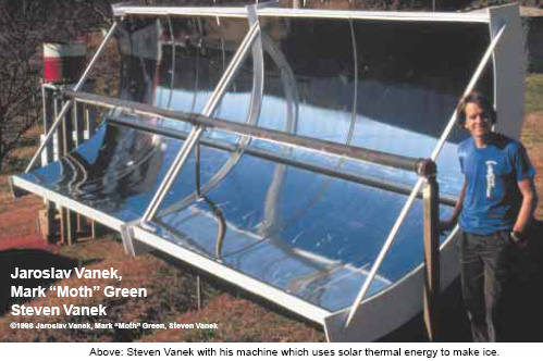 Also, a two-part article on Solar cooling, which concentrates on heat absorption with different colours, the strategic positioning of buildings and vegetation, practical roof overhangs and the like, to lower the temperature inside buildings in very hot locations. There are articles is on cooking with hydrogen, heating your house with hydrogen and using hydrogen with a barbecue. On the Home Power site there is information on how to use solar power to heat household water and you may find the Google video on how to make your own hot-water solar panel interesting and useful. This video is at and it shows very simple construction methods. It makes sense to reduce your essential costs by doing a few simple things which help. Cooling Using Heat. Most of our current refrigerators use electricity to drive a compressor to achieve cooling. Here is a patent from Albert Einstein (whom you may have heard of) and Leo Szilard which uses heat to power refrigeration instead of electricity. It is US Patent 1,781,541 titled “Refrigeration” and dated 11th November 1930.  Our invention relates to the art of refrigeration and particularly to an apparatus and method for producing refrigeration where the refrigerant evaporates in the presence an inert gas and more particularly, to the type disclosed in the Von Platen and Munters Patent No. 1,685,764 of 25th September 1928 and our British Patent No. 282,428. The objects and advantages of our invention will be apparent from the following description considered in conjunction with the accompanying drawing which shows more or less diagrammatically, a preferred embodiment of our invention. In the drawing, 1 is an evaporator which is normally placed inside the chamber which is to be cooled. A pipe 5 connects the upper part of evaporator 1 to the more intermediate portion of the condenser 6. Pipe 11 connects with the bottom of the evaporator 1 and extends into the condenser 6, at a level which is below the level of pipe 5. A cooling water jacket 12, surrounds the condenser and allows cooling water to flow through it. Pipe 27 connects the bottom of the condenser 6, to the lower part of a heat-exchanger jacket 28. The upper part of jacket 28, is connected to the lower part of generator 29 which is heated by any suitable method. Pipe 30 connects the upper part of generator 29 to a point near the bottom of evaporator 1 where it terminates in a distributor head 31. Pipe 30 runs inside pipe 5 so that there is a heat exchange between the fluids in those two pipes. Pipe 32 runs upwards from the lower part of generator 29 to connect with a container 33 which is positioned at a level which is above that of condenser 6. A source of heat 36, is applied to pipe 32 at a point above generator 29. Pipe 37 runs down from container 33, passing through the heat-exchanger jacket 28 and then on up to the top of condenser 6 where it terminates in a distributor head 35. Pipe 37 runs inside the cooling water jacket 12 so that the fluid passing through it will be cooled as it flows. A venting pipe 34 connects the upper part of container 33 with the upper part of condenser 6. The operation of the apparatus is as follows: A suitable refrigerant, for example, butane in liquid form, is held inside the evaporator 1. An inert gas, such as ammonia, is introduced into evaporator 1 through pipe 30 and it’s distributor head 31. The refrigerant evaporates in the evaporator in the presence of the inert gas due to the fact that the partial pressure of the refrigerant is reduced thereby and the resulting gaseous mixture passes through pipe 5 and into condenser 6. Here, the mixture comes into intimate contact with an absorption liquid, for example, water, which is fed into the condenser through pipe 37 and it’s distributor head 35. The ammonia gas is very soluble in water but the butane is quite insoluble, so the ammonia is absorbed into the water freeing the butane from the gaseous mixture. Thus, the butane assumes substantially the entire pressure inside the condenser, and that pressure is sufficiently high to cause its liquefaction at the temperature maintained by the cooling water. The specific gravity of liquid butane is less than that of the solution of ammonia in water and so stratification of the two liquids occurs with the liquid butane floating on top of the ammonia solution 26. The liquid butane passes from condenser 6, through pipe 11, and returns to evaporator 1, where it is again evaporated and the cycle repeated. Gravity causes the ammonia solution to flow from condenser 6 through pipe 27 and heat-exchanger jacket 28, into generator 29. Here, the application of heat causes the ammonia to be expelled from the solution in the form of a gas, which then passes through pipe 30 and distributor head 31, into evaporator 1, where it reduces the partial pressure of the butane, causing it to evaporate as already described. Water, containing very little ammonia in solution, passes from generator 29 through pipe 32 where it is further heated by the source of heat 36. This heating causes the formation of vapour in pipe 32 which lifts the liquid through this pipe and into container 33 and on from there under gravity through pipe 37 to condenser 6 and during its flow, this hot, low-concentration liquid is cooled by the heat-exchanger jacket 28. It is further cooled by the cooling water in jacket 12, and so reaches a condition where it can rapidly absorb ammonia in the condenser 6. Vapour entering container 33 through pipe 32, continues on it’s journey to the condenser 6 via the venting pipe 34. During the operation of this piece of equipment, the pressure existing in the various components is uniform with the exception of slight differences caused by columns of liquid needed to cause the fluids to flow. The pressure existing in generator 29 must be sufficiently greater than the pressure in the upper part of evaporator 1, in order to make vapour flow through distributor head 31. In other words, the pressure difference must be sufficient to overcome the liquid head marked h2. This excess pressure in the generator is balanced by the pressure created by the column of liquid marked h1 in the drawing. This means that h2 must be less than h1, otherwise there would be no flow. This patent of Einstein and Szilard seems to indicate that any source of heat such as a fire or a solar oven, should be able to produce cooling using a device which has no moving parts. It would probably be necessary to provide a trickle of water through the water cooling jacket, but apart from that, it looks like a device which could be used effectively by people who live “off the grid” and have little or no access to electricity. All in all, it is an interesting design. Solar panels. A very well-know method of producing electricity from what appears to be a renewable resource is the use of solar panels. It hardly seems worth mentioning these as sales are so well promoted but it is possible that the problems with them are not understood. This used to be the most expensive way of producing electricity, but by 2015, electricity from free-energy and renewable energy sources have now exceeded the electricity produced by fuels such as oil, coal and nuclear energy. Much of this gain has been improvements in solar panels with a move away from the silicon wafer based technology to the newer thin film methods of construction. That lowering in cost made the new solar panels viable as an investment for speculators and that drove up the installed volume enormously, with solar farms supplying the existing grid and getting paid for their input. Schemes in Germany produce 7% or 8% for investors. Details of this can be seen in the 2008 presentation here which explains the details very well. What is often not realised is that solar panels have a working life span and will need replacement at some later date. The life is quite good, typically ten to twenty years, but the price of replacement must be allowed for. Solar panels are not the only part of your electrical system which will need replacing. Generally speaking, solar panels are used to charge batteries which then power equipment, usually by using an "inverter" which changes a DC battery voltage to a mains voltage AC supply. The big snag is that the frequently used lead-acid batteries generally have a lifespan of about four years. They are expensive, heavy and as they contain lead, they are not easy to dispose of (legally). This is a major recurring cost and disposal problem. The Tesla Car company has a high power ‘battery’ design capable of storing solar power and then run an entire household. At the present time, the unit is about 4 feet x 2 feet x six inches which is about 1220 x 610 x 150 millimetres and the price is around US $3,500. Hopefully, the size and price will both reduce considerably as manufacturing volume increases. Another point which may not be realised with the older systems is that the current which can be drawn from a lead-acid battery without reducing its working life is very limited, quite apart from the fact that any lead-acid battery is only 50% efficient, requiring it to be fed twice as much current as it can supply afterwards. The safe discharge rate for a lead-acid battery is called the "C20" rate which just means that the allowable current is one which discharges the battery in a period of 20 hours. For example, if a new battery is rated as being a 100 Amp-hour ("100 AHr") battery, then the safe discharge rate is about 100 amps divided by 20, which is 5 amps. At twelve volts, a current of five amps is a power output of sixty watts. A washing machine needs about 2,200 watts for at least some of the time, so to power it (and nothing else at the same time) would take 37 of those 100 AHr batteries. Could you conveniently house 37 large batteries? How much do you think it would cost to replace them every four years? Please understand that I have nothing against solar panels and actually own some myself, but you need to be aware of the practical problems with using them and not imagine that buying them will give you free electricity for ever afterwards. The next factor to be considered is the fact that the power "rating" of a panel such as "120 watts" is not the amount of power which will be provided by the panel. It will provide that amount of power IF it is positioned exactly square-on to very strong sunlight in a region near the Equator. If the panel is not aimed exactly at the sun, then the panel output will be considerably lower. The sun moves around at a rate of fifteen degrees per hour, so your panel will only be aimed directly at the sun for about four minutes unless you have it mounted on a rotating platform and you push the platform round slowly to face the sun at all times. While that sounds complicated, it is actually not a difficult or expensive thing to arrange although most people don't bother to do that. Even though most solar panels operate on UV rather than visible light, any minor cloud cover drops the panel output quite noticeably. There is also the little detail that most solar panels only work in sunlight or with reduced output in very bright daylight. This means half the day does not contribute to electrical input and in winter, when the electrical need is greatest, the days are shortest, sunlight scarce and daylight quality very poor unless you live near the equator. The level of sunlight which you will receive drops off steadily the further you get from the equator as the light angle gets lower and lower. This also causes problems in winter with quite low obstacles casting a shadow on the panels and cutting the working time for the panel even further. The effect of all this is that you will need a far greater claimed panel wattage than your needs seem to require and I would suggest that you probably need between two and three times as many panels as the stated panel wattage would suggest that you need. Considering that chapter 10 shows how to run a generator on water, it would be cheaper to buy and replace a generator on a regular basis than to buy batteries and panels and having to replace them. A generator also runs at night and through the winter. However, if you are installing solar panels, please be aware that there are considerable differences between panels which have the same apparent rating. A key factor is the voltage produced by the cell under normal working conditions. This makes the difference between a good charging rate under poor conditions and a near-zero charging rate at those times. The good panels have a greater number of cells and the higher voltage produced can make a major difference, so check out the technical specification document on each panel you want to consider and pay attention to the voltage figures and not just the (maximum possible) "wattage" quoted by the manufacturer or sales person. The panels which I picked are made by Kyocera but do your own checking as designs change from year to year. At the present time, solar panels are only about 17% efficient which means that 83% of the power reaching them does not go to make electricity. Solar panels expand due to heat during the day and so need to be mounted in such a way that allows for this expansion and contraction during the day and night. As you don't want to over-charge a battery, it is generally considered essential to use a control circuit to prevent this happening. In real life, when you use the electricity generated on a daily basis, there is little or no chance of over-charging, but you can decide this for yourself. One recent development is to use the solar panel(s) to drive a battery-pulsing charging system. This has the major advantage that battery charging does not stop when the light falling on the panel produces a voltage which is too low to charge the battery bank directly. With a pulsing unit, the charging pulse voltage is largely independent of the input voltage and so a good charging rate can be produced in poor lighting conditions, including twilight. This can extend the battery charging period very substantially, especially in winter when there is less light. At this time, one of John Bedini’s companies is offering these units for sale. Assessing solar panels generally from the standpoint of knowing what the snags are, unless you live in a very good location on the planet and have a good deal of spare money to spend, then they are not a great solution, but this is something which you also need to decide for yourself. However, having said that, a scheme has recently been introduced in the UK and it appears to be a realistic option. Under this scheme, the householder does not buy the solar panels but merely pays to cover the cost of installing them. For example, this house:  has twenty-one panels mounted on the roof and the total cost to the home owner was just £500. The home owner receives a very much reduced electricity cost and expects to recover the installation cost within two years. Even in November at latitude 52 degrees North, these panels are performing well. Not having to pay for the purchase of the panels themselves makes an enormous difference to the viability of such an installation. I understand that the strategy behind this scheme is to increase the presently tiny percentage of electricity which is produced from renewable sources, by offering people a scheme which actually makes it worthwhile to have an installation. No batteries are used in the installation. Solar panels can be very useful items in spite of their very low efficiency and high cost. When thinking about solar panels people generally imagine a set of many large solar panels mounted on the roof of a house. The cost of doing that is far too great for most people to consider it. However, at this time, there are one billion people in the world who do not have any electricity at all. It appears that the most useful electricity feature for them would be electric lighting at night. With the components which have become available recently, providing good lighting at realistic cost is now possible. Small solar panels offered for sale as “10 watt, 12 volt” capacity can now be bought reasonably cheaply. Made in China, these panels can provide a current of just over half an amp These panels which have an aluminium frame are typically 337 x 205 x 18 mm in size and look like this:  Tests which I have run show that a 1000 lux very realistic level of lighting can be provided with a total of just 1.5 watts of electrical power. The best lighting source that I have found is the “G4” style, LED arrays made in China using the recent “5050” chip technology. These are cheap and have a very heavily non-linear light output for current draw, which is a fact which we can use to our advantage. These LED arrays come in “white” or “warm white” versions (my preference is the warm white variety) and they look like this:  With a diameter of 30 mm and pins which are easy to connect to, these are very convenient devices which have an excellent lighting angle of 160 degrees and a light output of 165 lumens for a 1.2 watt electrical input. One of the problems with such a unit is the selection of a suitable battery. Lithium batteries are excellent but the cost of a suitable lithium battery is ten times greater than the cost envisaged for the whole unit, effectively excluding lithium batteries. Lead-acid batteries are far too large, too heavy and too expensive for this application. Surprisingly, what appears to be the best choice is the very popular AA size Nickel-Manganese rechargeable battery which is 50 mm long and 14 mm in diameter:  Rated at up to 3 Amp-Hour capacity, they are very low cost, are lightweight and can be placed in a battery box like this:  The battery box can be adapted to hold seven batteries rather than the intended eight batteries, producing a nine volt battery pack with 1.2V batteries. If three of these battery packs are used with the solar panel, then there is no need for over-charging protection as NiMh batteries can deal with overcharging current if it does not exceed 10% of the battery’s milliamp-hour rating, and that simplifies the design very considerably. However, some of these small NiMh batteries do not live up to the maker’s claims and so you need to run a load test on any particular make of battery which you may consider using. For example, here are six different types of these batteries tested in groups of four, with a load of about 50 milliamps at five volts. The same load was used to test each of these batteries:  The results were most revealing:  The BTY 3000 batteries do not actually claim on the battery to be 3000 mAHr (although the sellers do) and so, the “3000” could just be a trading name. The tests results for the BTY 3000 were so staggeringly poor that the test was repeated three times with longer recharging time for each test, and the one shown above is the ‘best’ result. You will notice how far short it falls when compared to the Fusiomax 800 mAHr batteries costing only fifty pence each from the local Poundland shop. The terrible performance of the BTY 3000 batteries is only exceeded by the incredible SDNMY 3800 mAHr batteries which show almost negligible capacity in spite of their amazing claims of 3800 mAHr. I leave you to judge for yourself if the claims of some of these manufacturers are actually fraudulent. NiMh batteries are 66% efficient. That means that if you feed a 1-amp current into them for three hours, they should be able to provide a 1-amp current for two hours. A current of 1-amp is, of course, too high if the battery is to have a long working life of some years, so we would only ever charge a 3000 milliamp-hour NiMh battery at 300 milliamps or less. It is actually very difficult to determine when one of these batteries is fully charged as the battery voltage is not a reliable indication of the charge level. The battery starts to get warm when fully charged. A set of ten batteries which are nominally 12-volts, will have an actual voltage between 13-volts and 14-volts typically. Overcharging is not a problem with our small solar panel. However, light meter tests provide some very interesting results for the LED arrays. When using two LED arrays side by side in a light box, the figures for voltage / current draw / light produced using 1.2-volt NiMh batteries were: 9 batteries 11.7V 206 mA 1133 lux: 2.41 watts 470 lux per watt (the manufacturer’s intended performance) 8 batteries 10.4V 124 mA 725 lux 1.29 watts 562 lux per watt 7 batteries 9.1V 66 mA 419 lux 0.60 watts 697 lux per watt (a very realistic performance level) 6 batteries 7.8V 6 mA 43 lux 0.0468 watts 918 lux per watt This is very revealing information, showing that one of these LED arrays fed with just 33 milliamps can produce very impressive 210 lux lighting at a wide angle of illumination. To put that another way, feeding five LED arrays with 9 volts, generates a very acceptable 1000-lux lighting level for just 165 milliamps which is only 1.5 watts. That is spectacular performance. Equally impressive is what happens when the battery voltage drops when the battery is nearly fully discharged. The LED performance rises to combat the loss of voltage and even at a ridiculously small 3 milliamps fed into each LED, there is a 21 lux light output from each LED array. The effect is that while the lighting does dim slightly, it does so very gradually in a barely noticeable way. With three sets of genuine high-capacity AA NiMh batteries, we can expect a minimum of eight hours of continuous 1000-lux lighting from our desk lamp. That is a total of twelve watt-hours, and the solar panel feeding 66% efficient batteries at nine volts, is capable of replacing one of those usable watt-hours in twenty minutes. In other words, just two hours forty minutes of good daytime lighting can provide eight hours of 1000-lux lighting every night. The only moving component in this system is the On/Off switch and the circuit could not be any more simple than this:  All solar panels have a diode to prevent the panel drawing current from the batteries during the hours of darkness and it is not unusual for the panel to be supplied with a diode already connected in place. Personally, I would consider a fuse to be unnecessary but it is standard practice to fit one. The batteries are installed in a base box which supports the solar panel and gives sufficient weight to produce a very stable lamp. The five LED arrays are connected in parallel and fitted into a suitable lamp housing such as this one:  Only the flexible stem, 120 mm diameter lampshade and On/Off switch are used. While this is an exceptionally simple and robust design, it is actually an affordable and very desirable unit which can provide years of cost-free lighting at a very satisfactory level. The prototype looks like this: 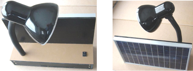 This is, of course, a perfectly ordinary and quite standard type of a solar-powered light. The difference here is that it is a very effective light suited to lighting a desk to a high level all night long. It is mobile and has a wide angle of lighting. It is also possible to extend the design very slightly, to provide an even longer period of lighting or if preferred, a period of even brighter lighting. This can be done by using eight batteries in each battery holder – which has the advantage that standard battery holders can be used without any need to adapt them to hold just seven batteries. This has the slight disadvantage that we do not want to supply the extra voltage to the LED arrays because doing that would cause a greater current draw than we want. We can overcome this by using an extra change-over switch and having two connections to each battery holder. The circuit could then become  With this arrangement, the lighting unit is fed by either eight batteries or by seven batteries, depending on the position of the change-over switch. When the solar panel is charging the batteries, all eight batteries per holder get charged no matter what position the extra switch is in. This has the advantage that when the battery voltage starts to drop after a few hours of powering the light, then the switch can be operated, raising the voltage reaching the lamp by the voltage of the extra battery, possibly producing a brightness exceeding the maximum when using just seven batteries in each battery holder. This arrangement has the slight disadvantage that the user could switch in all eight batteries from the beginning, producing a much higher current drain and while that would give a higher lighting level, the overall time is likely to be reduced. Mind you, it is possible that this might suit the user If this style of operation is chosen, then I suggest that the extra switch is located well away from the On/Off switch so that the user does not get confused as to which switch does which job. Perhaps the second switch might be located near the stem of the lamp support, like this: 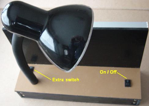 Without knowing much electronics, it is possible to make a more versatile version of this desk lamp. This can be done by providing a fully adjustable lighting level. For this, we used three 10-battery holders, each containing a full set of ten batteries, producing a nominal 12-volts but in reality, about 13.8 volts when fully charged. We would like the user to be able to adjust the voltage applied to the LED arrays in order to get the very high current-to-light output efficiency or a higher level for a shorter time, if that style of operation is preferred. This can be done quite easily, in a very simple and cheap way, using this arrangement where just one battery is shown to represent all three battery packs wired in parallel to produce a higher battery capacity:  Here, instead of feeding the battery voltage directly to the LED arrays, two cheap and widely available transistors are placed between the battery and the LEDs. These transistors control the voltage applied to the LEDs and that controls the current through the LEDs and the level of light produced. The chosen light level is set using the variable resistor “VR” and the light level can be turned down gradually, all the way to zero, so the unit could also be used as a night light if that was wanted. The physical layout of the components could be like this:  Here, the weight of the solar panel and the three battery packs give the unit stability if the lamp is bent in any direction. With four LED arrays, an excellent level of lighting results, however, I would suggest using five LED arrays as that gives an even wider range of lighting. A big advantage of this arrangement is that if the variable resistor is fitted with a knob like this:  then each user will become familiar with the particular light-level setting which suits the recharging rate. It also allows for short periods of very high level lighting if that ever becomes necessary. From a practical point of view, when the light is first switched on the battery voltage will almost certainly be over 13 volts. As we want about 9 volts applied to the LED arrays, some four volts need to be dropped off to stop the LEDs drawing excessive current and draining the batteries too quickly. In passing, it might be mentioned that the human eye is very bad at assessing light levels, and so, doubling the LED current (which would more than halve the length of lighting time) does not increase the visual effect by much, and so, controlling the current flow makes a major improvement in the length of time during which the light can be used each night. The lighting period each night is expected to be about eight hours. The transistors controlling the light level drop off some 1.4 volts, no matter what the current is. This is not a problem during the normal lighting period. However, if the lighting period is unusually long and the battery voltage is starting to drop, then it is possible to gain that extra 1.4 volts by using another switch to bypass the transistor control. It is wired so that the battery is connected directly to the LEDs in order to extract every last milliamp of current from the batteries. That extra 1.4 volts makes a major difference to a falling light level but it should not be used for any length of time on a fully charged battery (quite apart from the excessive current draw) as it is feeding the LEDs a voltage higher than the LED designer was expecting and while it does produce exceptional lighting, it is being very unkind to the LEDs. The bypass switch would be arranged like this:  Here, the extra switch marked “BOOST” short-circuits across the transistors and so connects the LEDs directly to the battery. The fuse shown is optional but if your wiring is not the best, then it is worth having in case your wiring creates a direct short-circuit across the batteries. A ‘slow-blow’ fuse rated at 1-amp would be a good choice as the normal current flow, even on BOOST with a fully charged battery, will be less than one amp if five LED arrays are used. It is also possible to use a variable resistor which has the On/Off switch built into it:  Also shown in the diagram is the solar panel which is connected to the batteries at all times, even bypassing the fuse. It is connected through a diode such as a 1N4007 so that the panel will not draw current from the batteries during the hours of darkness. To make sure that the two switches are not mixed up by the user, I suggest that the extra switch “SW2” is positioned well away from the On/Off switch:  Of course, it is not essential to use a commercial, adjustable lamp such as this. Instead, the LED arrays could be mounted on a home-made strip attached to the back of the solar panel plate and possibly, angled slightly downwards if a desk or table is the main place to be lit. In either case, it is advisable to put a piece of frosted plastic across the LEDs as they can be lit so brightly that they can be difficult to look at. Also, just because this is intended primarily as a desk lamp, there is nothing to stop the user tipping the light upwards to light the whole room. Actually, the room will probably be fairly well lit even when the main lighting area is a desk or table even if located at one end of the room. The construction sequence might be:
While this solar desk lamp can be built this way at quite reasonable cost even with one-off prices on individual prices, a really major improvement is achieved if they are being manufactured, especially if made in China. Firstly, all the effort of making the housing disappears as a cheap custom plastic case does away with all that time and effort as the solar panel has its wires connected, fed through the existing hole in the case and then the panel is just pushed into place. The battery packs are then assembled and pushed into place, the circuit connections made and the case clicked closed on its own or held in place by self-tapping screws. The component prices drop enormously with bulk purchasing, reducing the not unreasonable one-off price by a major factor, especially since wages in China are very low by our standards. The result is an attractive, useful product with a very large market and a unit price capable of taking full advantage of that large sales base. Test procedures: If the unit does not work straight off, then step-by-step tests are needed to locate and fix the problem. These are simple, common sense tests. If you do not have a voltmeter, then it is worth purchasing one as they are now very cheap.
1. One 10-watt, 12-volt solar panel. 2. Thirty AA-size, 1.2V NiMh batteries with a capacity near 3000 mAHr if possible. 3. Three AA battery boxes each holding 10 batteries. 4. Three battery clip connectors to fit the battery boxes. 5. One 1-amp diode type 1N4007 or similar. 6. One 22K Linear variable resistor and graduated knob to fit the shaft diameter. 7. One 10% quarter watt (or higher rated) 22K resistor (colour bands red/red/orange) 8. One BC109C transistor. 9. One TIP3055 transistor. 10. Five G4 LED arrays. 11. One desk lamp (optional) 12. Two rocker switches. 13. One fuse holder (of any type) and a 1-amp fuse. 14. Ten metres of insulated, stranded wire rated for 1-amp or higher current. 15. Rigid sheet material 6 mm thick (possibly MDF). 16. One small off-cut of laminate flooring 85 x L (typically 337) mm 17. Adhesive. 18. Rubber feet or soft material for the underside of the desk lamp. Notes: Rocker switches are generally cheaper as the Change-over version with three switch tags, and so these have been shown. For this design, only On/Off action is needed. Press the “1” end of the rocker down, and the two contacts used are then the two farthest away from the “1”. The TIP3055 transistor is the more recent version of the 2N3055 and is a particularly good transistor for this application being much easier to connect to. While the TIP3055 is strongly recommended, other power transistors may be used. No heat sink is needed if the transistor can handle 8 amps or more (the TIP3055 can handle 15 amps and 90 watts). The BC109C transistor has a very high gain between 200 and 800, which is useful in this application, but a major advantage of it is that it switches off fully with pretty much zero leakage current, while I have some of the very popular 2N2222 transistors which don’t switch off properly at all and so are effectively rejects. Most alternative transistors are highly inferior to the BC109C and so, if it is not readily available, then it is worth ordering. The 1N4007 diode is the cheapest readily available diode. It is rated for 1000-volt operation which is of course, of no interest here and so the lower voltage 1N4001 through 1N4006 diodes are perfectly suitable although slightly more expensive as they are less popular. While one diode is shown in this document, people who are expert in electronics are inclined to use three connected in parallel as that passes current more freely. That would cost an extra 6 pence at 1-off prices in the UK. Some people are really put off by electronics of any kind, so here is a version of the solar desk lamp which effectively, has no electronics at all:  The only control on this version is the On/Off switch. As we no longer have any control over the voltage applied to the LED arrays installed in the lamp shade, and since that voltage controls dramatic changes in current draw, we need to reduce the number of 1.2V NiMh batteries from ten to seven. It is a matter of choice whether you use three or four sets of seven batteries. If 10-battery battery boxes are used, then a wire can be soldered across the gap left by the three omitted batteries. The general construction is the same as before, with a rocker On/Off switch being installed instead of the variable resistor. As with all of these solar units, the important thing is to switch the light off when it is not in use, to avoid the next charging session being hindered by unwanted current draw through the light. The general layout of the unit can be the same:  There are other variations which can be low-cost and very versatile. For example, instead of connecting the three battery packs together, they can be kept separate from each other, individually housed with the same circuit, each driving one of the LED arrays:  Here, three identical units are charged from the solar panel, which can be any size or wattage, although a ten-watt panel would be considered to be the minimum for daily use. Each unit is in effect, just a wide-beam, high-intensity, high-capacity solar torch which can be dimmed and which will stand securely when unsupported. It has the advantage that the units can be constructed one at a time, and if necessary due to time constraints, or perhaps, very poor daylight, just two or even one unit can be charged from the entire solar panel output. If manufactured and sold, then the units could be sold separately, allowing a lighting system to be extended and improved when additional funds become available (or when the user has tried one unit and discovered how effective it is). Each unit is easy to understand and use:  A built unit of this type looks like this from the front: 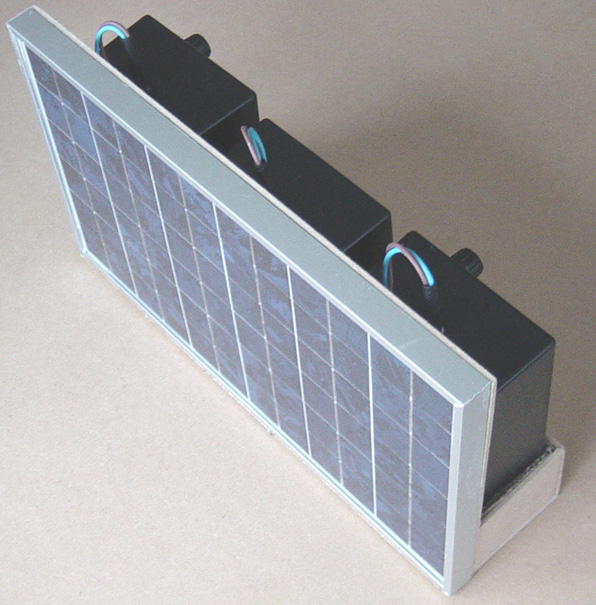 and like this from the back: 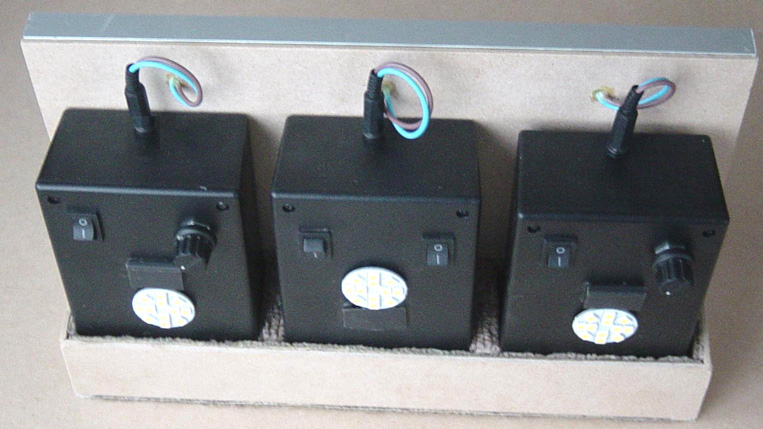 While these particular units have just one of the LED arrays each, tests run since that construction show that with manual dimming control, two LED arrays per unit would be more satisfactory. Also, if the second LED array is mounted on the side of the box, then the lighting angle increases from 160 degrees to 250 degrees which should be helpful for indoor lighting of a room. The units could, of course, be used in different rooms simultaneously and there is the option of carrying one around for lighting anywhere. Again, the construction is very simple and the same circuit as for the desk lamp shown above, can be used in each box. If good-quality NiMh AA-size batteries are used, each of the mobile units is capable of providing good light for eight hours, which means that if it gets dark at 4 pm (16:00), lighting is available until midnight as a minimum, at which point in time, the user should be going to sleep. If a very powerful single source of lighting is needed, it is possible to use a larger solar panel, or for a more compact unit, two of the 12-volt 10-watt panels shown above. The arrangement can use the same simple manual control of lighting level and the same booster switch for even greater lighting for a few minutes. The arrangement can be like this:  When closed over, the face of solar panel P1 faces that of solar panel P2, protecting both when the unit is being carried. An early prototype of this style of construction with the panels open, looks like this:  A magnetic catch is used to hold the hinged panel securely closed when the unit is being carried and a small flap is attached beside the magnetic catch to overcome the slightly excessive looseness of the hinges. The unit does not need to be as deep as this experimental model was made. The front view of the unit, ready to receive the frosted plastic cover for the LED arrays, looks like this:  The underside of the unit is covered with a soft protective layer to ensure that it does not scratch any surface on which it is placed. In order to avoid the need for overcharging circuitry, this unit has six battery packs and so, having ten LED arrays, the duration of lighting is about the same as that of the desk lamp, although obviously, the light output can be much greater. With the greater lit area of ten LED arrays, a lower actual current can be used while still providing a good level of lighting. With fully charged batteries switched to the ‘boost’ setting, this unit puts out more light than a 100-watt incandescent bulb powered by the mains. Tested in daylight, that looks like this:  Let me stress again, that these units are not difficult to build and they don’t call for any great knowledge of electronics. Alternatives: While the systems shown above are effective and reasonable cost, it is possible to make them more efficient. With battery packs of ten NiMh 1.2V AA cells, when fully charged, we get more than 13-volts, when we actually want 9-volts for effective lighting. We get this by using two transistors to drop the voltage down to 9-volts. The current flow is about 135 milliamps and so, the voltage drop of 4-volts at that current flow is a power loss of 540 milliwatts, which is a significant percentage of the power used to generate the lighting. By arranging things in a different way, we can reduce that power loss very considerably, IF we don’t mind the user being involved in controlling the lighting level. We could do this by tapping into our 10-battery pack and using an extra 3-way switch which allows us to start off with 8 batteries and when the voltage starts to drop, switch to 9 batteries as the extra fully-charged battery would make a major difference to the lighting. Then when the voltage of the 9 batteries starts to get low, the tenth battery can be switched in:  Whether or not this is worth doing is a matter of opinion in spite of the longer and/or brighter lighting. With 8 batteries in use, the power saving is 350 milliwatts and with 9 batteries the power saving is 175 milliwatts. The lighting power is 1215 milliwatts, so these represent 29% and 14.5% of that power. If it is decided to use this arrangement, then the battery boxes can be tapped with additional output wires connected between batteries 8 and 9 and between 9 and 10. The operational sequence would be: 1. Eight batteries switched in: variable light control. 2. Nine batteries switched in: variable light control. 3. Ten batteries switched in: variable light control. 4. Boost switch closed: fixed lighting level as batteries discharge to their minimum level. Each of these switched levels gives a new lease of life to the lighting system, but it does require the intervention of the user, although that intervention is very minor. It does not matter whether it is the Plus end of the battery chain, or the Minus end which is switched. The way that the battery boxes are constructed, actually make it more convenient to make the two extra connections at the Minus end of the stack:  Medical usage The applications of the solar desk lamp shown above are intended for home or office use. There is one other serious lighting requirement and that is for doctors working in isolated rural areas, far from any electrical grid but also, very far from fuel supplies for running a conventional generator which is the only known option for most of them. For example, it can take a doctor two days of travelling to get some more generator fuel. If we apply a slight alteration to the desk lamp and sacrifice the long period of lighting, we could boost the light output from 1000 lux right up to 2,700 lux for an hour or two of very brightly lighting. I can see no reason why two or three of those would not give more than adequate light for night time emergency surgery when placed on stands or suspended from the ceiling. Being self-contained and mobile, an assistant could hold and aim one to illuminate exactly where the light is needed. The basic solar desk lamp operates off seven 1.2V batteries in series. Eight batteries in series would boost the light level to 1730 lux at the cost of much higher current draw and reduced period of lighting. Increasing the batteries to nine would raise the light level to a massive 2,700 lux with a current draw so high that there might only be lighting for perhaps one hour, but that doesn’t matter in an emergency where a life could be saved. To achieve this emergency level of lighting all that is needed is an ordinary 4-way rotary switch which replaces the On/Off switch as it can do that job as well, otherwise the construction remains identical. The arrangement could be like this:  360 Degree Lighting for Africa The desktop lighting unit described above is very effective for lighting in cold areas where houses have windows with glass in them and where the roof does not project much beyond the house wall. However, housing style is very different in places like Africa where strong sunlight is experienced all year round and so a house roof is likely to project well beyond the wall in order to give improved shade for outside seating. Anna Brüderle’s “Solar Lamps – Africa” marketing research published by GIZ GmbH Uganda, has raised many previously unknown facts which should result in physical design changes. To date, I have produced three solar prototype lighting units, but these have been based on recharging using light coming through a glass window. That is not really possible in the African environment surveyed, as it shows: 1. Using a solar panel indoors is not possible due to lack of windows and major roof overhang. 2. Using a solar panel light being recharged outdoors is liable to have it stolen. 3. Using an outside solar panel connected by a wire is liable to damage and/or child injury when at play. The survey-area lifestyle has the following characteristics: 1. Seven people living in one building is not unusual and so 360-degree lighting is preferred. 2. The kitchen is normally separate and has no windows and yet needs meal-preparation lighting. 3. Burning a fuel for lighting is liable to cause poor health from the fumes produced. 4. Child education is hindered by lack of lighting. 5. Light usage is usually 3 or 4 hours at night plus 2 hours in the morning. 6. Tests with 100 lumen lighting level have been considered to be satisfactory. 7. Lamps are normally placed on the dining table during meals and hung from the ceiling at other times. 8. When carried outside, a narrow forward lighting arc of say, 90-degrees is preferred for safety. 9. Units with variable lighting levels are preferred but why is not specified – probably light duration. In these houses, there can be internal walls which do not reach the ceiling so that light in the central room spills over into the additional rooms. These features call for a lighting unit which is:
 The triangular shape makes for easy construction and is very robust from an engineering point of view. It also cuts down the number of faces needed for 360-degree lighting to just three. The versatility is increased greatly if two faces are hinged:  This arrangement allows two faces to be aligned with the fixed front face, giving all horizontal lighting in one direction which is a very, very bright arrangement. The two faces can be moved further around to give the wanted narrow forward beam for walking outdoors. If desired, the lighting level can be controlled by making the On/Off switch a three-pole four-way rotary switch:  This arrangement gives Off, One panel, Two panels and Three panels of illumination, but it could also be that instead of switching off an entire panel that the switching illuminates one LED array per panel, two LED arrays per panel and three LED arrays per panel. If ordinary 10-battery holders are used, then the lamp housing can be made more compact as the corners of the triangle are not needed. The battery packs fit in like this:  Giving a compact hexagonal shape which is strong and has the same lighting capability. The sides extend above the top and below the base so that the unit can stand on a flat surface either way up. The hinges need to be stiff so that they hold their position when set to the desired angle.  The addition of a simple hinged flap to the base allows a tilted option which imitates the downward lighting style of a desk lamp:  The Chinese LM2587 DC-DC converter from h-quality_electronic selling on eBay in October 2015 for £3.17 including postage, has COP>1 performance:  Ten LED arrays are brightly lit by it with just a 2.88 volt input. Measurements using three NiMh batteries connected in series, indicate an input of 800 mA at 3.33 volts (2.664W) driving the 10-LED array displays with 389 mA at 10.3 volts (4.01W) which is COP=1.5 and has the advantage of reducing the number of batteries needed for good LED array lighting. In practice, four batteries in series are used. This converter also charges ten NiMh batteries from 10.5V to 13V (falling eventually to 12.5V) in just 30 minutes at 50 mA current draw. A very useful addition to this sort of lighting system is using a simple constant-current circuit to control the current draw and give a steady, unchanging lighting level throughout the entire period of illumination. I have found that zener diodes do not perform well when supplied by batteries with gradually falling voltage. A much better method of getting a reference voltage is to use ordinary diodes and use their normal voltage drop as a reference.  As the transistor TR1 has a voltage drop across it’s Base - Emitter junction equivalent to the voltage drop across one diode, we use two diodes to create a voltage reference level and so maintain a 0.7 volt voltage drop across resistor R2. R1 is chosen to give about 3 milliamps of current flowing through point “A” and the diodes can be any silicon type, perhaps 1N4148 diodes. The transistor needs to have a high gain and be able to handle the desired current flow through the load. A 2N2222 transistor appears to work well in this circuit. Resistor R2 is chosen to give the desired current flow, forcing that current flow through the load (provided that the battery can supply that current). The load can be the DC-DC converter shown above and the battery voltage can quite easily be 5 volts. If there is concern about the power handling ability of a 2N2222 transistor, then two or more can be used in parallel with the Bases connected together, the Collectors connected together and the Emitters connected together. It may well be possible to charge a second battery pack when the lights are on and then, when the lights are switched off, to use that second battery to recharge the main battery pack. Alternatively, a 10 watt solar panel, as used with the desk light, can be used to recharge the battery pack through a length of low-resistance cable and a plug and socket. There is also the possibility of providing a USB socket for recharging mobile phones. It should be able to supply 5 volts at 500 milliamps and draw no current when not in use. The user should be alerted to the fact that extensive use of the USB socket may reduce the power in the battery pack used for powering the lighting. The prototype worked very well indeed when carried out of doors in a totally unlit and unfamiliar place. If the suspension cord is made longer and an additional hook is provided near the base, then the unit can be suspended indoors with all of the LED arrays facing downwards, which with their 160 degree angle of illumination would give excellent 360 degree lighting.  Throughout this ebook there are many designs for generating electricity, getting pure water and my websites also have some information on health issues. These things have all been approached from the point of view of you, as a single individual, doing something in spite of having very limited finance, workspace, tools and skills. There is a very interesting and inspiring video at billionsinchange.com/film which describes some of the work of Manoj Bhargava and his colleagues. Manoj produced a drink called “Five-hour Energy” which became a major commercial product, leaving Manoj with four billion US dollars. That has given him the freedom to use his common sense and practical attitude to start to deal with the major issues of half the population of the world – free-energy, clean water and health improvement. With his finance, he works with much larger solutions to these problems and some of his designs are most interesting. He avoids any mention or use of unconventional systems. For the provision of electricity, he proposes the use of an adapted bicycle which spins a generator and charges a battery which can slowly charge mobile phones and provide lighting. It is said that one hour of pedalling can produce 24 hours of (low-power) electricity. His design looks like this:  This is the generator which is spun by belt gearing from the pedals. The wheel with the large rim forms a flywheel and although he does not mention it, the flywheel causes an energy gain. The basic build looks like this:  the cyclist pedals in a reclining position and the belting drives the gearing which spins the generator shaft:  The design produces a good deal more electricity than I would have expected:  These metres show more than 100-watts being generated. However, production cost is always a major factor in these things, especially since the people who need them most are the people with least money. Perhaps a version which is driven by an existing bicycle might ease the situation – that method is already used for some exercise equipment. Another factor which might be missed by designers is the fact that the people needing this equipment are labourers and will be tired after a long, physical working day. Of course, the pedalling would be less effort for them due to their much higher muscle strength. The addition of two small motors like Chas Campbell does, would probably make the design self-powered and do away with most of the construction – pedals, belts, seat, etc. Low-cost Cooling Systems When most people think of air-conditioning systems they think of large pieces of equipment which are expensive to buy and expensive to run and which are mounted in one fixed location. While those systems are certainly effective (although, often noisy in operation), there are other ways of improving living, travelling and working conditions. Ways which are not very expensive to buy and which are not expensive to run. Many people have made effective air coolers and shared their designs using web videos, and I should like to thank them for showing what they have achieved. Simple cooling systems can use two different methods of operation. One method is to use ice which has been produced using an ordinary refrigerator or freezer (those being very common in places where air-cooling would be considered an asset). Another method uses the well-known principle that when water evaporates, it draws heat from its surroundings as part of the process. The general idea is to cool some air and then use a fan to blow that cooler air to where it is most effective for the user. Typically, cooling is most needed inside buildings and inside vehicles. Inside buildings, mains electricity is often available. Inside vehicles, twelve-volt or similar levels of DC power are generally available. In both locations, a solar panel (possibly aided by a car battery for night time operation) can operate a useful system. What we are talking about here, is a small system which will not be as effective as a large commercial unit, but yet is something which can make a great improvement in a small area. Something which does not seem to occur to many people is that you can have more than one of these units operating in a room or vehicle. While I am delighted that people have shared their simple designs on the web, they usually assume that the components which they have used are available to everybody, and that is very much not the case as the items which are readily available locally vary enormously at different places around the world. For that reason, I should like to discuss the basic principles used so that when any chosen design uses something which is just not available locally, you can choose a suitable alternative which is readily available locally at low cost. Let us start with indoor cooling. The unwanted heating comes mainly from the sun shining in through windows, and from heat leaking in through the walls because the outside of the walls is being heated by sunlight falling directly on it or by hot air flowing along the outer surface of the wall. Of these two main sources of indoor heating, the sun coming through the windows is generally the greater source of heat. If a room has one or more windows facing the sun and one or more windows which do not face the sun, then a first step might be to use shiny silver-faced insulation cut to exactly fit the windows through which the sun shines. Curtains can generally hold the insulation in place on their own, but if that is not convenient, then a few small pieces of adhesive tape work adequately and can be used again day after day. The outer shiny layer reflects most of the sunlight back out of the room. The outer surface of the insulation sheet heats up as not all of the light is reflected, but the insulation layer stops most of that heat actually entering the room, resulting in a major improvement in the room temperature, although the light level is reduced considerably as well. This is suitable for people living in apartment blocks where there is no convenient access to the outside of windows. In the case of people living in bungalows or other low buildings, the use of shade should not be overlooked as it is a very effective way of reducing temperature. This effect is even very noticeable in cooler countries on sunny days as there is a very marked effect driving down a road which has large trees on the same side as the sun. With the car windows open, there is a very considerable drop in temperature when the car enters the area shaded by the trees. I am not suggesting growing trees to give shade as that is not convenient for most people, but a simple overhang or a temporary or retractable awning may be possible to block direct sunlight from coming in through the windows. An awning or overhang has no running costs. Let’s take a look at one of the systems shown on the web. This one is being used to lower the temperature in a house with a floor space of 1,700 square feet (158 square metres) and the video presentation is here and deals with a house where the outside daytime temperatures exceed 100 degrees Fahrenheit (38 degrees Centigrade), making the indoor temperatures uncomfortable. With his cooler running and the outside air 90F (32C) the air entering the house is 69F (20.5C) which means that the warmest place in the house is around 75F (24C). As hot air rises, the hottest place in the house is the highest point and very sensibly, he has mounted an extraction fan which pulls the hottest air out of the house and pushes it into the attic (which is open to the outside and so vents to the outside air). For the system to be effective, all of the windows and doors are kept closed except for the one which has the cooling system mounted on it. This blows the hottest air out of the house and at the same time, draws fresh air in through the cooling system. You can see the attic fan mounting here: 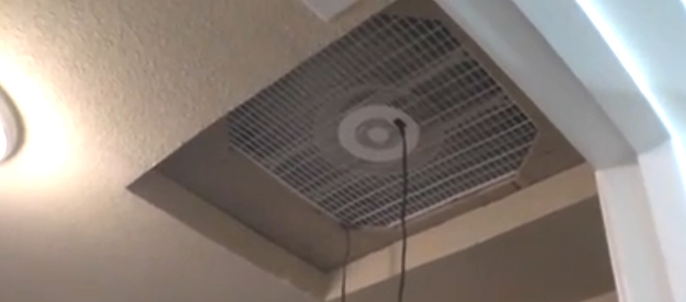 The entering air comes in through a large window which has evaporative pads clamped to the window frame by a simple timber mounting system: 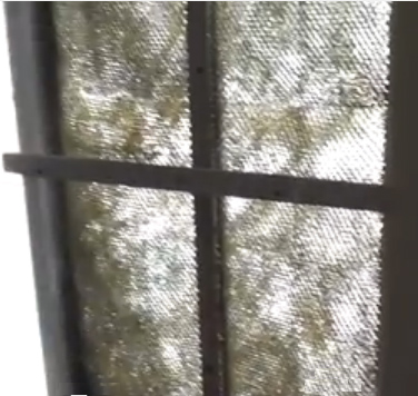 The pads are kept cool by droplets of water pumped to the top of the window by a small submersible pump submerged in a large plastic storage box filled with water: 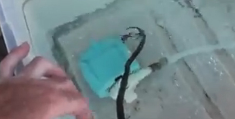 Excess water is returned to the reservoir by two short lengths of plastic guttering as shown here: 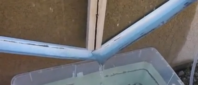 The particular fan and pump used draw a total of 120 watts, and so as one “unit” of electricity is 1000 watts for one hour, running the system all day and night is a power usage of 120 /1000 x 24 = 2.88 Kilowatt-Hours per day. The construction costs in America in 2013 were about US $60. If solar panel power is to be used with a lead-acid battery, please remember that the battery is only 50% efficient, which means that it will only return half of the current that you put into it. Also, please remember that solar panels are rated for bright sunlight shining directly on them at exactly 90-degrees to the panel and in normal operation, the panel output is far less than the retailer’s claimed wattage, not to mention the fact that the panel will only be operational during daylight hours. As against that, many such installations do not need to be run day and night and so solar operation may be quite economical. Also, 120 watts is a large amount of input power and could almost certainly be reduced for smaller installations. It is not unusual for the cooling of a single room to be satisfactory in many situations. For this, using a very small self-contained unit is often considered to be adequate. These units generally use a fan from an old computer, typically, running on 12-volts and drawing about 4-watts. For the cars which still do not have air conditioning, a fan of that type is very convenient as it can run directly off the ‘cigarette lighter’ socket or from a direct wire connection through a fuse, to the car battery. For indoor use, any tiny 12V mains power unit can power the unit for minimal cost. These units have been made in all sorts of shapes and sizes and by all accounts, do very well when easing excessive heat. This very small unit uses a 12V 3.6-watt computer fan blowing air into a small insulated box containing ice and can be seen here. In spite of being rated as a 12-volt unit, the fan can actually run on a low-power USB socket. Cold air exits from the holes drilled beside the fan: 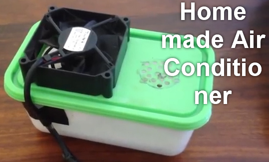 This one here uses a 21-inch (535 mm) square box fan with a simple evaporation system attached to it: 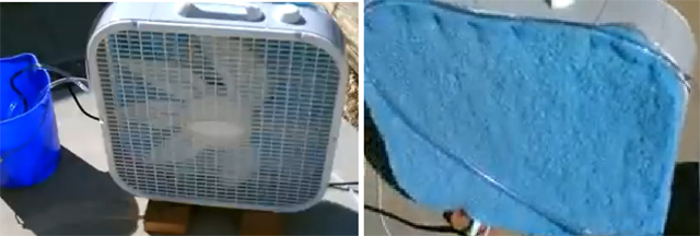 This one here also uses a computer fan: 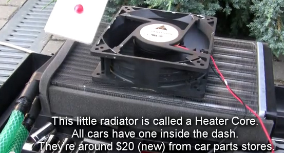 This one here uses a Wal-Mart battery-powered fan which means that with a solar panel to recharge extra rechargeable batteries when the unit is in use, the unit could be very, very cheap to run. An ordinary ice-box is used, so perhaps cold drinks are a possible additional option: 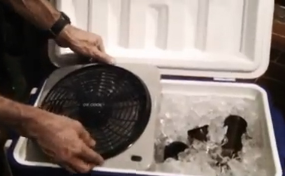 Also using an ordinary ice-box this unit has a wooden push-fit lid and uses a car fan: 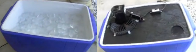 The unit here is intended for use inside a car, although obviously, it could easily be operated inside a house using a small 12-volt mains unit. The preferred coolant is 2-litre plastic bottles filled with water which has been frozen solid in a freezer. The builder states that the bottles will cool a car down faster than ice does and the bottles also provide a longer period of cooling than ice can: 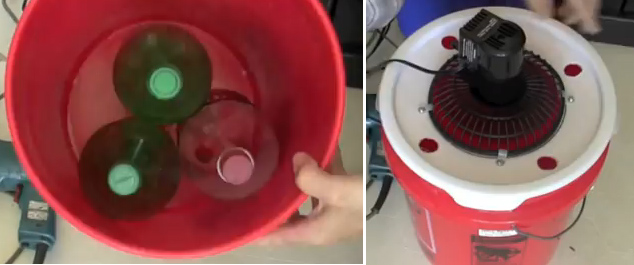 The fan is set to blow air into the container and the cold air exits through the four holes drilled around the fan. This design suggests that as a temporary measure, standing some frozen 2-litre bottles in front of an ordinary fan could well provide effective cooling in a room. Using ice or bottles of frozen water is energy efficient as refrigerators and freezers are generally about 300% efficient. That is, the cooling energy is three times greater than the electrical energy used to achieve that cooling. These are only a few of the many ingenious and simple designs which could make life much more comfortable in conditions which are generally considered to be excessively warm. A little time spent examining these and similar units shown on in web videos should give you confidence to build your own, or if you prefer, to design and build your own simple cooler system. Sensible Building There is a famous American Architect called Michael Reynolds. He has a very low opinion of conventional housing which he considers to be a "compartment" which is wholly dependent on outside power sources. His opinion is justified. He produces buildings which have been named "EarthShips" by his wife and the name has caught on world-wide. The objective is to make a home which has no utility bills at all. A building which collects its own water and uses that water several times. Generates its own electrical power. Provides its own heating and cooling. Grows some of its own food, and uses materials many of which have been disposed of by previous owners - vehicle tyres, aluminium drink cans and glass bottles. An EarthShip can be a stylish and comfortable home:  Although, obviously, the overall cost of the structure and furnishings depends on the quality chosen by the owner. This particular EarthShip is one shown in the film "Building Off The Grid" which can be found on the peer-to-peer network, took fifty volunteers four weeks to complete the basic structure and then another team of workers were paid to supply and install the fittings and fixtures. The structure faces South and has twelve large solar panels mounted along the top of the greenhouse area. Although this picture does not show it, there is a drainage ditch along the back of the property to divert heavy rainwater coming off the protecting hillside behind the property:  The walls of the property are seven feet thick (2.13 metres) in order to allow the use of fairly simple materials and more importantly, to provide thermal mass which keeps the inside of the building warm in winter and cool in summer. There are no significant bills for heating or cooling and normal electrical equipment is run from the solar panels. The design of the electrical system is elderly and as shown, it requires lead-acid batteries to be replaced about every four years. A smaller system driving DC battery pulse-chargers would provide fast battery charging and the batteries would never have to be replaced. However, this particular house was built using twelve large solar panels. Initially, three were used to provide electrical power during the building period. These were just propped up against the hillside near the battery box which contains control equipment, a battery bank and a mains inverter: The battery box used during construction is very simple:   The overall design is set up for construction by unskilled workers under the supervision of a few experienced people, but let me point out that this is a Civil Engineering project and so a reasonable level of understanding is needed before you build one for yourself. For example, the roof spans across the gap between the outside walls. The loading on any support beams increases with the cube of the distance between those walls. That means that if you were to double the width of the room, then the support needed to hold the roof up increases by a factor of eight times !! This can, of course, be achieved, but you really need to be aware of it. In this particular building, the roof is held up by numerous tree trunks which have been stripped and prepared for the job:  These beams are very heavy and are quite capable of causing serious injury if not handled carefully and sensibly. They form the joists which support the roof and there is a gap of about one foot between them, so many of them are needed. They are secured to the top of the wall by steel rods driven through them and on into the wall. The main construction is with vehicle tyres and about a thousand are needed for the building. Each is filled with earth which is compacted carefully and then they are stacked in a staggered bank and grouted in place using mortar. In passing, most American get confused with concrete products, so to clarify: 1. Cement is a grey powder material. 2. Mortar is a mixture of cement and sand, wetted with water, which sets into a solid. It is normally used to fill the gap between concrete blocks or clay bricks. 3. Concrete is Mortar which has pebbles mixed into it. Also used in these constructions is adobe which is mud and straw mixed together. Properly made adobe dries into a solid block and is used in hot dry countries as a main building material, but it needs to be waterproofed against future rain unless a temporary structure is sufficient.  The tyres are overlapped in successive rows, forming a stable structure and then grouting is applied between them. The outside is enclosed in an earth bank and the inside is later smoothed over. This style can be seen at the back door alongside the greenhouse area:  The constructional details can be found in the books by Michael Reynolds “Garbage Warrior”, “EarthShip”, “Comfort in Any Climate”, etc. or full constructional plans can be bought direct from Michael. water flows under gravity. Water used for washing is then used for toilets and then on to water plants which grow food. Water is collected from the roof, filtered and then held in massive plastic tanks which have a total capacity of 6000 US-gallons (22,700 litres). There are no pumps as all water flows under gravity. Water used for washing is then used for toilets and then on to water plants which grow food.  The positioning of the tanks is important as they have to be just below the roof so that rainwater flows into them under gravity and yet they have to be higher than shower-heads for the same reason (unless a pump is used for showers). A simple filter is used to remove any blown material which finds its way into the water intake. For all that unskilled people can do most of the work, there are a number of trade skills which are needed – plumber for the piping, electrician for the electrics, engineer for levelling and concrete work, glazier for the double glazing units, etc.  Steel bars called “rebar” are driven into the walls and positioned to the exact height, and a reinforced concrete ring is cast around the top of the walls to give overall strength to the structure, before the heavy tree trunks are put into place. A nice feature of this style of construction is using coloured glass bottles in walls to allow light through and allow artistic designs to give the impression of stained glass  When the wall is finished off and the bottles polished, the effect is really good, especially since the glass bottles are effectively free being recycle materials. However, choosing them as part of your living room is a matter of personal taste:  It is quite normal to have conventional styles of construction:     The important thing to remember about this house is that the walls are thick and so have a high thermal mass. The ‘greenhouse’ section all along the South side of the main building forms a heat buffer and water filtration. The roof is seriously effective with a one-inch thick layer of timber with tarred paper covering it, and then eight-inches of polystyrene on top of that and a ridged metal roof on top of that. That is a seriously effective thermal layer. This style of construction is definitely worth considering. Patrick Kelly http://www.free-energy-info.tuks.nl http://www.free-energy-info.com http://www.free-energy-info.co.uk http://www.free-energy-devices.com |